Table of Contents
Advertisement
Quick Links
Advertisement
Table of Contents

Related Manuals for Consew 104-1T


Summary of Contents for Consew 104-1T
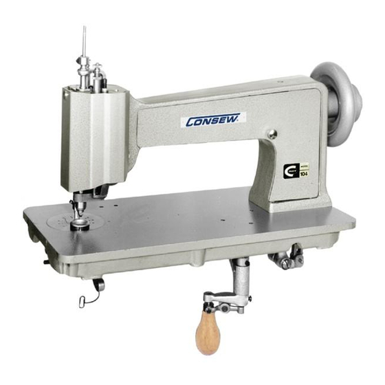
- Page 1 104-1T 104-2T 104-3T PARTS BOOK AND INSTRUCTION MANUAL...
-
Page 2: Table Of Contents
INDEX DESCRIPTON ..................2 SPEED ....................4 TO OIL THE MACHINE ................ 3 NEEDLES, NIPPLES AND THREAD ........... 4 TO REMOVE, REPLACE AND SET NEEDLE AND NIPPLE ....5 TO THREAD THE MACHINE ............... 7 LEARNING TO OPERATE THE MACHINE.......... 9 TO OPERATE THE MACHINE ............. -
Page 3: Descripton
DESCRIPTION Embroidery machine makes the single thread chain stitch and can be quickly adjusted to make the drop or moss stitch without unthreading the machine. It is designed for ornamenting or embroidering curtains, upholstery, dresses, scarf, gloves, table covers, lace, etc. The machine al so can make linen and towels for hotels, etc., by stitching a name into the material. -
Page 4: To Oil The Machine
TO OIL THE MACHINE To insure easy running and prevent unnecessary wear of the parts which are in movable contact, the machine requires oiling. Oil should be applied to the plac es designated by unlettered arrows in Figs. 1, 2, 9, and 10. Fig. -
Page 5: Needles, Nipples And Thread
Fig. 2, Oiling points of the front of the machine Fig. 2 shows the arm cover removed for the purpose of oiling. This arm cover can be removed after taking out thumb screw W, Fig. 8. If the machine is used continuously, oil should be applied at least once each day. -
Page 6: To Remove, Replace And Set Needle And Nipple
TO REMOVE, REPLACE AND SET NEEDLE AND NIPPLE When it is necessary to change the needle and nipple on the machine, first select another n eedle and corresponding nipple. Then lower the presser bar, loosen wing screw B, Fig. 3 and remove needle hol der A and needle from top of machine. - Page 7 Fig. 3, Adjustments on the machine A. Needle holder B. Wing screw for needle holder C. Thumb screw for regulating pressure on presser foot D. Needle plate E. Tension regulating lever F. Tension regulating plate G. Tension complete H. Tension bracket I.
-
Page 8: To Thread The Machine
TO THREAD THE MACHINE Place the cone of thread in a convenient position on the floor. Three thread eyelets are furnished with machine. These eyel ets should be fastened to the underside of the t able as shown at 1, 2 and 3, Fig. 4. Eyelet 1 should be located directly above the cone of thread. - Page 9 Fig. 4, Threading machine Fig. 5, Threading machine...
-
Page 10: Learning To Operate The Machine
LEARNING TO OPERATE THE MACHINE NOTE: When in operation the machine pulley must always turn over away from operator. Mark a design (see Fig. 6) on a 12 inch square piece of cloth. Place cloth under presser foot so that needle will enter cloth at point 1. -
Page 11: T Regulate The Pressure On The Presser Foot
TO REGULATE THE PRESSURE ON THE PRESSER FOOT The pressure on the presser foot i s regulated by the thumb screw C, Fig. 3. To increase the pressure, turn t he thumb screw over to the right or downward. To decrease the pressure, turn the thumb screw over to the lef t or upward. -
Page 12: To Adjust The Length Of Stitch
TO ADJSUT THE LENGTH OF STITCH The length of stitch is adj usted by screw T, Fig 8. To lengthen the stitch, loosen locking l ever U and turn screw T over to the l eft or upward, then tighten locking lever U. To shorten the stitch, loosen lockin g lever U and turn the screw T over to the right or downward, then tighten locking lever U. -
Page 13: To Regulate The Pressure On The Nipple
TO REGULATE THE PRESSURE ON THE NIPPLE The pressure on the nipple is regulated by the thumb screw P, Fig. 8 at the top of the machine. T o increase the pressure, turn this thumb screw over to the right or downward. -
Page 14: To Set The Looper
TO SET THE LOOPER Turn the machine back on it s hinges and turn handl e K, fig. 10 and wing screw B, Fig. 3 to the front. Loosen set screw X, Fig. 10 of the operating worm gear Y, and turn the gear slightly , until the notch in the looper is in its correct position as instructed above. -
Page 15: Pile Or Moss Stitch
PILE OR MOSS STITCH The raised pile or moss stitch or produced by adjusting the machine so that it will drop the stitches in loose loops on the material. To accomplish this, turn handle K to the front , loosen the wing screw B, Fig.3 and turn the needle holder so that the hook of the needle will pint directly to the back of the machine, then tighten the wing sc rew. - Page 17 Ref. NO. Parts No. Description P1-1 8135 ARM SIDE COVER P1-2 ARM SIDE COVER THUMB SCREW P1-3 8154 ARM POSITION PIN P1-4A 8153-A ARM SCREW (LONG) P1-4B 8153-B ARM SCREW (SHORT) P1-5 8134 ARM HEAD COVER P1-6 5227 ARM HEAD COVER THUMB SCREW P1-7 8150 ARM HEAD POSITION PIN...
- Page 19 DESCRIPTION REF. NO. PARTS NO. P2-1 8017-B DRIVING PULLEY P2-2 8015 DRIVING PULLEY SLEEVE P2-3 8018 DRIVING PULLEY SLEEVE SCREW P2-4 8016-A DRIVING PULLEY SLEEVE BUSHING P2-5 DRIVING PULLEY SLEEVE BUSHING SCREW P2-6 8012 ARM SHAFT DRIVING FLANGE WITH SCREWS P2-7 8013 ARM SHAFT DRIVING FLANGE POSITION SCREW...
- Page 21 DESCRIPTION REF. NO. PARTS NO. P3-1 8110-A STITCH ROTATING GEAR (UPPER) WITH SET SCREW P3-2 8142 STITCH ROTATING GEAR (UPPER) SET SCREW P3-3 8111 STITCH ROTATING GEAR SHAFT P3-4 8180 STITCH ROTATING GEAR SHAFT BUSHING P3-5 STITCH ROTATING GEAR SHAFT BUSHING SCREW P3-6 8112-A STITCH ROTATING GEAR (LOWER) WITH SET SCREW...
- Page 23 REF. NO. PARTS NO. DESCRIPITON P4-1 8085-B LOOPER OPERATING CONNECTION (CAM END) P4-2 8177 LOOPER OPERATING CONNECTION JOINT P4-3 8174 LOOPER OPERATING CONNECTION JOINT PITMAN P4-4A 8175 LOOPER OPERATING CONNECTION JOINT PITMAN NUT (UPPER) P4-4B 8176 LOOPER OPERATING CONNECTION JOINT PITMAN NUT (LOWER) P4-5 8178 LOOPER OPERATING CONNECTION JOINT HINGE STUD...
- Page 25 DESCRIPTION REF. NO. PARTS NO. P5-1 8123 STARTING TRIP LEVER (INTERMEDIATE) P5-2 8124 STARTING TRIP LEVER (INTERMEDIATE) HINGE SCREW P5-3 8122 STARTING TRIP LEVER ROD P5-4 8113 STITCH ROTATING GEAR BRACKET P5-5 8143 STITCH ROTATING GEAR BRACKET SCREW P5-6 8149 STITCH ROTATING GEAR BRACKET POSITION PIN P5-7 8114-A...
- Page 26 PARTS FOR 104-3T ONLY...
- Page 27 REF. NO. PARTS NO. DESCRIPTION P6-1 8065 PRESSER FOOT SLIDE BAR SPRING P6-2 8066 PRESSER FOOT SLIDE BAR SPRING PLUNGER P6-3 8067 PRESSER FOOT SLIDE BAR THUMB SCREW (PRESSURE REGULATING) P6-4 8161 PRESSER FOOT SLIDE BAR THUMB SCREW NUT P6-5 8063 PRESSER FOOT SLIDE BAR GUIDE P6-6...
- Page 29 REF. NO. PARTS NO. DESCRIPTION P7-1 8303 NEEDLE HOLDER P7-2 8027 NEEDLE P7-3 8309 ARM HEAD SLEEVE P7-4 8305 NEEDLE HOLDER OPERATING COLLAR P7-5 8306 NEEDLE HOLDER GUIDE BLOCK P7-6 8307 NEEDLE HOLDER THUMB SCREW P7-7 8333 NEEDLE HOLDER GUIDE BLOCK SCREW P7-8 8308 ARM HEAD SLEEVE CAP...
- Page 31 REF. NO. PARTS NO. DESCRIPTION P8-1 8057 NIPPLE CARRIER BELL CRANK P8-2 8058 NIPPLE CARRIER BELL CRANK HINGE STUD P8-3 5225-C NIPPLE CARRIER BELL CRANK HINGE STUD SET SCREW P8-4 8023 NEEDLE OPERATING SLIDE P8-5 8028 ARM HEAD SLEEVE CAP P8-6 5176-A ARM HEAD SLEEVE CAP SCREW...
- Page 33 PRESSER FOOT SLIDE BAR THUMB SCREW NUT P8-52 8065 PRESSER FOOT SLIDE BAR SPRING P8-53 8066 PRESSER FOOT SLIDE BAR SPRING PLUNGER P8-54 8033 FEED SLIDE BLOCK (FOR 104-1T) 8033-A FEED SLIDE BLOCK (FOR 104-2T) P8-55 8034-A FEED LEVER P8-56 8144 FEED LEVER HINGE PIN...
- Page 35 DESCRIPTION REF. NO. PARTS NO. P9-1 8336 CORD SPOOL P9-2 8331 CORD SPOOL SPINDLE P9-3 CORD SPOOL SPINDLE THUMB NUT P9-4 CORD SPOOL SUPPORT P9-5 CORD SPOOL SUPPORT P9-6 P9-7 8329 CORD SPOOL FRICTION SPRING P9-8 ADJUSTING SCRW P9-9 8140 CORD SPOOL FRICTION SPRING SCRW P9-10 P9-11...
- Page 37 DESCRIPTION REF. NO. PARTS NO. P10-1 AC01 SCREW DRIVER P10-2 AC02 SCREW DRIVER P10-3 AC03 SCREW DRIVER P10-4 8073-A PRESSER FOOT SHOE (RUBBER) ※ P10-5 8170 TWEEZERS ※ P10-6-1 8056-1 NIPPLE ※ P10-6-2 8056-2 NIPPLE ※ P10-6-3 8056-3 NIPPLE ※ P10-6-4 8056-4 NIPPLE P10-6-5...
Need help?
Do you have a question about the 104-1T and is the answer not in the manual?
Questions and answers