Table of Contents
Advertisement
Quick Links
Advertisement
Table of Contents

Related Manuals for Consew 104-10T


Summary of Contents for Consew 104-10T
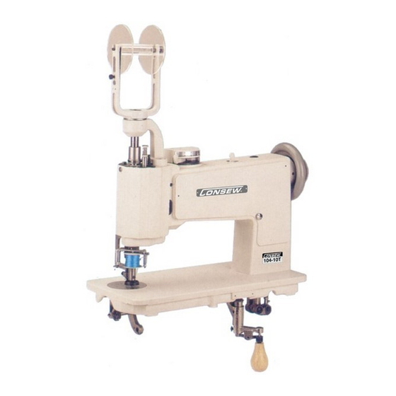
- Page 1 104-10T PARTS BOOK AND INSTRUCTION MANUAL...
-
Page 2: Table Of Contents
INDEX 1. SPECIFICATIONS ................2 2. DESCRIPTION ................... 2 3. SPEED ....................2 4. TO OIL THE MACHINE ..............3 5. NEEDLES, NIPPLE AND THREAD ........... 4 6. TO REMOVE, REPLACE AND SET NEEDLE AND NIPPLE .... 5 7. TO THREAD THE MACHINE ............. 7 8. -
Page 3: Specifications
1. SPECIFICATIONS Stitch specification : Single thread, chainstitch Speed : 1500 stitches per minute Feed : Universal feed movement Stitch Length : Maximum 5 m/m Presser foot lift : 7 m/m Needle bar stroke : 14 m/m Needle used : System 137 x 1(chainstitch) 137 *1 SM (Moss stitch) Motor : 200W(1/4HP), Single or three phase, 4 poles, clutch... -
Page 4: To Oil The Machine
4. TO OIL THE MACHINE (Fig. 1, 2, 11 & 12) To insure easy running and prevent unnecessary wear of the parts which are in movable contact, the machine requires oiling. Oil should be applied to the places designated by unlettered arrows in Fig. 1,2,11and 12. -
Page 5: Needles, Nipple And Thread
Fig. 2 shows the arm cover removed for the purpose of oiling. This arm cover can be removed after taking out thumb screw, Fig. 10. If the machine is used continuously, oil should be applied at least once each day. 5. -
Page 6: To Remove, Replace And Set Needle And Nipple
needle must fit in the nipple and slide freely without side play. Nipples are available in size numbers similar to those of the needles, and for general work the number of the nipple should be the same as that of the needle. The nipples for embroidery machine are available in the following kinds, as per Fig. - Page 7 needle, when laid around the needle, will have sufficient space to pass without touching the sides of the needle hole. Loosen thumb screw (L) and turn plate (D) until correct needle hole is in line with needle, then tighten thumb screw (L). Next, insert the selected nipple (N) into the lower part of nipple holder (O) and tighten screw securely with the screwdriver, Insert the nipple holder (O) into the nipple carrier (Fig.
-
Page 8: To Thread The Machine
A. Needle bar B. Needle bar operating collar set screw C. Presser foot slide bar thumb screw D. Needle plate E. Tension regulating lever F. Tension regulating plate G. Tension complete H. Tension bracket Tension controller spring J. Presser foot lifter K. - Page 9 With the right hand, turn handle (A) straight to the left, having started the machine, quickly bear down and up on handle (A) so the needle will pick up the thread for one stitch. Keep handle (A) in same position and with the threading wire (B), draw thread directly toward you, laying end of thread loosely on needle plate after t comes up thread needle hole.
-
Page 11: Learning To Operate The Machine
8. LEARNING TO OPERATE THE MACHINE (Fig.8) Note: When in operation the machine pulley must always turn over away from operator. Mark a design (see Fig.8) on 30cm (12 inch) square piece of cloth. Place cloth under presser foot so that the needle will enter cloth as at point 1. Turn handle ig. -
Page 12: To Regulate The Pressure On The Presser Foot
10. TO REGULATE THE PRESSURE ON THE PRESSER FOOT (Fig.4) The pressure on the pre sser foot is regulated by the thumb screw , Fig.4. To crease the pressure, turn the thumb screw over to the right or downward. To crease the pressure, turn the thumb screw over to the left or upward. -
Page 13: To Adjust The Length Of Stitch
12. TO ADJUST THE LENGTH OF STITCH (Fig. 10) The length of stitch is adjusted by screw , Fig. 10. To lengthen the stitch, osen locking lever and turn screw over to the left or upward, then tighten locking lever shorten the stitch, loosen locking lever and turn the screw over to the... -
Page 14: The Looper
To raise the nipple, insert a screwdriver in hole , Fig. 11 and loosen the set screw therein. The eccentric adjusting stud can then be turned by the wrench provided so that nipple can be set at desired height, then tighten the set screw in hole 14. -
Page 15: To Set The Looper
15. TO SET THE LOOPER (Fig. 4 & 12) Turn the machine back on its hinges and turn handle , Fig. 12 and screw Fig. 4 to the front. Loosen set screw , Fig. 12 of the operating worm gear And turn the gear slightly, until the notch in the looper is in its correct position as instructed above. -
Page 16: To Adjust The Tension Of The Braiding
Note: Do not change the lever while the clutch is engaging. If do so, it may cause the machine to damage. 17. TO ADJSUT THE TENSION OF THE BRAIDING (Fig. 10) It is the best for the nor al braiding embroidery works that the braid spool racket , Fig. -
Page 17: Pile Or Moss Stitch
loosens. For tightening cord ig. 7) Tighte n the screw , Fig. 7 so that the rotation of the cord spool becomes low. ) For tightening braid (Fig. 7) Tighten the screw , Fig. 7 so that the rotation of the braid spool becomes slow. - Page 18 1. MACHINE FRAME & COVERS COMPONENTS...
- Page 19 REF. NO. PARTS NO. DESCRIPTION P1-1 AM1114-10 MACHINE FRAME P1-2 8181 ARM TOP SCREW P1-3 8470 ARM HEAD COVER P1-4 5227 ARM HEAD COVER THUMB SCREW P1-5 8466-A SPOOL CARRIER DRIVING GEAR COVER P1-6 4015 SPOOL CARRIER DEIVING GEAR COVER SET SCREW P1-7 8434 ARM SIDE COVER...
- Page 20 3. ARM SHAFT MECHANISM COMPONENTS...
- Page 21 REF. NO. PARTS NO. DESCRIPTION P3-1 8403 ARM SHAFT BUHSING P3-2 98-A ARM SHAFT BUSHING SET SCREW P3-3 8404 DRIVING PULLEY SLEEVE BUSHING P3-4 DRIVING PULLEY SLEEVE BUSHING SET SCREW P3-5 8406 ARM SHAFT GEAR SLIDING KEY P3-6 8407 ARM SHAFT GEAR SLIDING KEY SPRING P3-7 ARM SHAFT ASSEMBLY WITH REF.
- Page 22 5. ARM HEAD PARTS COMPONENTS (NO.1)
- Page 23 DESCRIPTION REF. NO. PARTS NO. P5-1 8472 ARM HEAD P5-2 8020 ARM HEAD SCREW (UPPER) (LONG) P5-3 8021 ARM HEAD SCREW (UPPER) (SHORT) P5-4 8022 ARM HEAD SCREW (LOWER) P5-5 8150 ARM HEAD POSITION PIN P5-6 8145 ARM HEAD POSITION PIN P5-7 S-8462 SPOOL CARRIER DRIVING GEAR GUIDE WITH REF.
- Page 24 7. ARM HEAD PARTS COMPONENTS (NO.2)
- Page 25 DESCRIPTION REF. NO. PARTS NO. P7-1 8067 PRESSER FOOT SLIDE BAR THUMB SCREW P7-2 8161 PRESSER FOOT SLIDE BAR THUMB SCREW NUT P7-3 8065 PRESSER FOOT SLIDE BAR SPRING P7-4 8066 PRESSER FOOT SLIDE BAR SPRING PLUNGER P7-5 8322-A PRESSER FOOT SLIDE BAR P7-6 8139 PRESSER FOOT SLIDE BAR ADJUSTING SCREW...
- Page 26 9. ARM HEAD PARTS (NO.3), BRAID LEADER & SPOOL CARRIER COMPONENTS...
- Page 27 DESCRIPTION REF. NO. PARTS NO. P9-1 8042 FEED BELL CRANK P9-2 8044 FEED BELL CRANK ROLLER P9-3 8045 FEED BELL CRANK ROLLER SCREW P9-4 8046 FEED BELL CRANK SPRING P9-5 8043 FEED BELL CRANK HINGE STUD P9-6 5225-C FEED BELL CRANK HINGE STUD SET SCREW P9-7 8057 NIPPLE CARRIER BELL CRANK...
- Page 28 11. GEAR CHANGE LEVER, SPOOL CARRIER DISENGAGING LEVER & INTERMEDIATE GEAR PARTS COMPONENTS...
- Page 29 DESCRIPTION REF. NO. PARTS NO. P11-1 8439 GEAR CHANGE LEVER COVER P11-2 8440 GEAR CHANGE LEVER COVER SET SCREW P11-3 8441 GEAR CHANGE GRADUATED PLATE P11-4 8435 GEAR CHANGE LEVER BASE P11-5 113-B GEAR CHANGE LEVER BASE SET SCREW P11-6 8437-1 GEAR CHANGE LEVER P11-7...
- Page 30 13. FEED ROTATING GEAR & STOP BRACKET PARTS COMPONENTS...
- Page 31 DESCRIPTION REF. NO. PARTS NO. P13-1 8424 FEED ROTATING SHAFT BRACKET P13-2 113-A FEED ROTATING SHAFT BRACKET SET SCREW P13-3 8146 FEED ROTATING SHAFT BRACKET POSITION PIN P13-4 8423-A FEED ROTATING GEAR (REAR) P13-5 8142 FEED ROTATING GEAR SET SCREW P13-6 8420 STITCH ROTATING SHAFT...
- Page 32 15. FEED ROTATING SHAFT MECHANISM COMPONENTS...
- Page 33 REF. NO. PARTS NO. DESCRIPTION P15-1 8110-A SPOOL CARRIER GEAR DRIVING BEVEL GEAR P15-2 8142 SPOOL CARRIER GEAR DRIVING BEVEL GEAR SET SCREW P15-3 8458 SPOOL CARRIER GEAR DRIVING GEAR SHAFT P15-4 8459 SPOOL CARRIER GEAR DRIVING GEAR SHAFT BUSHING P15-5 4078 SPOOL CARRIER GEAR DRIVING GEAR SHAFT BUSHING SET SCREW...
- Page 34 17. LOOPER OPERATING MECHANISM COMPONENTS...
- Page 35 P17-12 8099 LOOPER BRACKET P17-13 8152 LOOPER COLLAR P17-14 129-B LOOPER COLLAR SET SCREW P17-15 8158 LOOPER BRACKET SET SCREW P17-16 8150 LOOPER BRACKET POSITION PIN P17-17 LOOPER OPERATING CONNECTION ASSEMBLY (REF. NOS. 18-28) P17-18 S-8444 LOOPER OPERATING CONNECTION P17-19 8174 LOOPER OPERATING CONNECTION JOINT PITMAN P17-20...
- Page 36 19. TENSION REGULATING PARTS & STITCH ROTATING HAND LEVER PARTS COMPONENTS...
- Page 37 REF. NO. PARTS NO. DESCRIPTION P19-1 TENSION BRACKET ASSEMBLY (REF. NOS. 2-17) P19-2 8127 TENSION REGULATING PLATE P19-3 8128 TENSION REGULATING PLATE HINGE SCREW P19-4 8129-A TENSION REGULATING SPRING P19-5 8130-A TENSION REGULATING SPRING SCREW STUD P19-6 8125 TENSION BRACKET P19-7 8131 TENSION REGULATING LEVER...
- Page 38 21. CORD SPOOL & BELT COVER COMPONENTS...
- Page 39 DESCRIPTION REF. NO. PARTS NO. P21-1 8336 CORD SPOOL P21-2 8331 CORD SPOOL SPINDLE P21-3 7012-A CORD SPOOL SPINDLE WASHER P21-4 8332 CORD SPOOL SPINDLE THUMB NUT P21-5 8487 CORD SPOOL BRACKET P21-6 8329 CORD SPOOL FRICTION SPRING P21-7 8140 CORD SPOOL FRICTION SPRING SCREW P21-8 4356...
- Page 40 23. STANDARD ACCESSORIES...
- Page 41 DESCRIPTION REF. NO. PARTS NO. P23-1 AC-01 SCREW DRIVER (LARGE) P23-2 AC-02 SCREW DRIVER (MEDIUM) P23-3 AC-03 SCREW DRIVER (SMALL) P23-4 AC-04A OILER P23-5 AC-05 P23-6 AC-08 ACCESSORY BOX P23-7 8166 SCREW EYE P23-8 8157 BED CLAMPING THUMB SCREW P23-9 8165 MACHINE HINGE CONNECTION P23-10...
Need help?
Do you have a question about the 104-10T and is the answer not in the manual?
Questions and answers