Table of Contents
Advertisement
Quick Links
Installation and Operation Instructions
FOR YOUR SAFETY: This product must be installed and serviced by a professional service technician,
qualified in hot water boiler and heater installation and maintenance. Improper installation and/or operation
could create carbon monoxide gas in flue gases which could cause serious injury, property damage, or
death. Improper installation and/or operation will void the warranty.
If the information in this manual is not
followed exactly, a fire or explosion may
result causing property damage, personal
injury or loss of life.
Do not store or use gasoline or other
flammable vapors and liquids in the vicinity
of this or any other appliance.
WHAT TO DO IF YOU SMELL GAS
• Do not try to light any appliance.
• Do not touch any electrical switch; do not
use any phone in your building.
• Immediately call your gas supplier from a
nearby phone. Follow the gas supplier's
instructions.
• If you cannot reach your gas supplier, call
the fire department.
Installation and service must be performed
by a qualified installer, service agency, or gas
supplier.
Installation and
Operation Instructions for
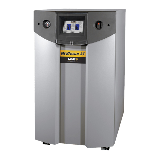
N
Modulating Boiler
Model NTH1000
1,000 MBTU/h
Model NTH1200
1,200 MBTU/h
WARNING
T
EO
HERM
Assurez-vous de bien suivres les instructions
données dans cette notice pour réduire au
minimum le risque d'incendie ou d'explosion ou
pour éviter tout dommage matériel, toute blessure
ou la mort.
Ne pas entreposer ni utiliser d'essence ni d'autres
vapeurs ou liquides inflammables dans le
voisinage de cet appareil ou de tout autre appareil.
QUE FAIRE SI VOUS SENTEZ UNE ODEUR DE GAZ:
• Ne pas tenter d'allumer d'appareils.
• Ne touchez à aucun interrupteur. Ne pas vous
servir des téléphones dansle bâtiment où vous
vous trouvez.
• Appelez immédiatement votre fournisseur de
gaz depuis un voisin. Suivez les instructions du
fournisseur.
• Si vous ne pouvez rejoindre le fournisseur de
gaz, appelez le sservice des incendies.
L'installation et l'entretien doivent être assurés par
un installateur ou un service d'entretien qualifié ou
par le fournisseur de gaz.
Document 1255E
LC
®
Water Heater
Model NTV1000
1,000 MBTU/h
Model NTV1200
1,200 MBTU/h
AVERTISSEMENT
Advertisement
Table of Contents
Troubleshooting

Related Manuals for Bradford White LAARS NEOTHERM LC NTH1000


Summary of Contents for Bradford White LAARS NEOTHERM LC NTH1000
- Page 1 Installation and Operation Instructions Document 1255E Installation and Operation Instructions for HERM ® Modulating Boiler Water Heater Model NTH1000 Model NTV1000 1,000 MBTU/h 1,000 MBTU/h Model NTH1200 Model NTV1200 1,200 MBTU/h 1,200 MBTU/h FOR YOUR SAFETY: This product must be installed and serviced by a professional service technician, qualified in hot water boiler and heater installation and maintenance.
-
Page 2: Table Of Contents
LAARS Heating Systems Table of Contents SECTION 1 General Information SECTION 6 Water Connections Introduction ............1 Boiler systems ..........19 Warranty ............1 6.A.1 Boiler System Piping: Model Identification ........... 1 Hot Supply Connections ......... 19 6.A.2 Boiler Cold Water Make-Up ......19 Safety Notes ............. - Page 3 NeoTherm LC Boilers and Water Heaters SECTION 9 Setup and Configuration SECTION 12 Troubleshooting Review of Lead Lag Control System ....47 12.A Potential Setup and Synch Problems ..... 98 9.A.1 About Lead Lag Operation ......47 12.A.1 Controller Synchronization ......98 9.A.2 Lead Lag Modulation Cycle ......
- Page 4 LAARS Heating Systems...
-
Page 5: Section 1 General Information 1.A Introduction
NeoTherm LC Boilers and Water Heaters Page 1 SECTION 1 General Information 1.A Introduction Touch Screen Display (behind the plastic cover Power switch This manual provides information necessary for the which slides downward) installation, operation, and maintenance of LAARS Heating Systems NeoTherm boilers and water heaters. -
Page 6: D Safety Notes
LAARS Heating Systems Page 2 1.D Safety Notes Safety Notes are used thoughout this manual to bring attention to the presence of hazards with various risk levels and to off er important information concering the life of this product. There are 3 basic types. WARNING Indicates an imminently hazardous situation which, if not avoided, can or will result in death or serious injury and can... - Page 7 NeoTherm LC Boilers and Water Heaters Page 3 WARNING NOTE: All installations must be made in accordance with 1) American National Standard Z223.1/NFPA54-Latest Electrical Shock Hazard Edition “National Fuel Gas Code” or Electrical shock can cause severe injury, death or 2) CSA B149.1 “Natural Gas and Propane Installation property damage.
-
Page 8: E Model Overview
LAARS Heating Systems Page 4 Model Overview Power switch Ducted air inlet Rating Plate Touchscreen (on outside panel) Protective Cover Electrical box (slides downward) Pressure and PRV and temperature flow switch gauge Blower 1 (under bezel) Outlet Automatic temperature gas valves sensors Inlet Manual... -
Page 9: G The Installation Kit
Dimensional Data NeoTherm LC Boilers and Water Heaters Page 5 NeoTherm LC 1000 & 1200 Dimensions (continued) Figure 3. Dimensions overall 1.G The Installation Kit The unit is shipped in a single crate with a boxed installation kit that contains these components. •... -
Page 10: Section 2 Locating The Unit
LAARS Heating Systems Page 6 SECTION 2 Locating the unit Note - When located on the same wall, the units 2.A Locating the unit combustion air intake terminal must be installed a minimum of 12” below the exhaust terminal. There This unit may be installed indoors or outdoors. -
Page 11: Section 3 Venting And Combustion Air
NeoTherm LC Boilers and Water Heaters Page 7 SECTION 3 Venting and Combustion Air General Venting 3.A General Venting This product requires a special venting system. Refer to venting supplier’s instructions for complete parts list and method This unit requires a special venting system. Refer Do not mix venting suppliers and models in venting of installation. -
Page 12: B Combustion Air
LAARS Heating Systems Page 8 3.B Combustion Air following descriptions.) Where ducts are used, they shall be of the same cross-sectional area as the free These boilers and water heaters must have area of the openings to which they connect. provisions for combustion and ventilation air in accordance with the applicable requirements Method 1: Two permanent openings, one... -
Page 13: Ducted Combustion Air
NeoTherm LC Boilers and Water Heaters Page 9 Method 2: One permanent opening, commencing duct applications, two elbows must be installed on within 12” (300 mm) of the top of the enclosure, the end of the inlet to act as a vent terminal. In shall be permitted. -
Page 14: C Venting
LAARS Heating Systems Page 10 3.C Venting (See Table 7.) The vent can terminate through the roof, or through an outside wall. The use of polypropylene vent material has WARNING Selection of improper vent materials for been accepted by CSA for use with exhaust and installations that are installed in closets, or will be combustion. -
Page 15: D Locating The Vent And Combust Air Terminals
NeoTherm LC Boilers and Water Heaters Page 11 be installed per the vent manufacturers certified installation instructions. It is the responsibility of the appropriately licensed technician installing this unit to use ULC S636 certified vent material consistent with the requirements as described in the Venting and Combustion Air section. - Page 16 LAARS Heating Systems Page 12 U.S. Installations (see note 1) Canadian Installations (see note 2) A= Clearance above grade, veranda, porch, 12 inches (30 cm) 12 inches (30 cm) deck, or balcony See note 6 See note 6 B= Clearance to window or door that may be Direct vent only: 12 inches (30 cm);...
-
Page 17: Side Wall Combustion Air Terminal
NeoTherm LC Boilers and Water Heaters Page 13 IMPORTANT: All terminals must be placed so that they remain at least 12” above the expected snow line. Local codes may have more specific requirements, and must be consulted. Refer to the NFPA54 National Fuel Gas Code and your local codes for all required clearances for venting. -
Page 18: Vertical Vent Terminal
LAARS Heating Systems Page 14 above the combustion air terminal. for installation of hard-wired carbon monoxide detectors. Multiple vent kits should be installed such that the horizontal distance between outlet group a. In the event that the side-wall horizontally and inlet group is 36” (90 cm). (See Figure 8.) vented gas fueled equipment is installed in a crawl space or an attic, the hard-wired carbon The vent outlet must be at least 12”... -
Page 19: F Outdoor Installation
NeoTherm LC Boilers and Water Heaters Page 15 placed in operation, while the other appliances remaining connected to the common venting system Outdoor Installation are not in operation. This unit may only be installed outdoors in 1. Seal any unused openings in the common applications where the outdoor temperature doesn’t venting system. -
Page 20: Section 4 Gas Supply And Piping 8.B
LAARS Heating Systems Page 16 SECTION 4 Gas Supply and Piping WARNING Open flame can cause gas to ignite and result 4.A Gas Supply and Piping in property damage, severe injury, or loss of life. All Installations must conform to the National Fuel Gas Code ANSI Z223.1/NFPA54, and/or local codes. - Page 21 NeoTherm LC Boilers and Water Heaters Page 17 NATURAL GAS TO SIZE PIPING: REQUIRED Measure linear distance from meter outlet to last boiler. Add total input of all CU FT SIZE / HR. boilers and divide by 1000 to obtain cu ft / hr required.
-
Page 22: Section 5 Pump Requirements 8.D
1000 6" 6" 100 ft 30 m 1200 6" 6" 100 ft 30 m Installations in the U.S. require exhaust vent pipe that is a combination of PVC and LAARS Heating Systems Page 18 CPVC complying with ANSI/ASTM D1785 F441, polypropylene pipe that complies with ULC S636, or stainless steel complying with UL 1738. -
Page 23: Section 6 Water Connections
NeoTherm LC Boilers and Water Heaters Page 19 SECTION 6 Water Connections Section 6 is divided into TWO parts. water temperatures. Therefore, to get the best low Section 6A covers Boilers models designed return temperature with multiple boilers, pipe as for hydronic heating. -
Page 24: Boiler Freeze Protection
LAARS Heating Systems Page 20 6.A.3 Boiler Freeze Protection 6.A.4 Condensate Drain Trap A condensate drain trap is included with the unit and WARNING is designed to drain the boiler of condensate. The Glycol must not be used in domestic hot water vent condensate should be drained through a drain applications. - Page 25 NeoTherm LC Boilers and Water Heaters Page 21 Low temp. radiant zone Space heating zone circuits Space heating zone circuit System pump Air vent 4 pipe dia. max. 4 pipe dia. max. 4 pipe dia. max. Water feed controls 4 pipe dia. max. Note - This drawing is a schematic representation of a piping style,...
- Page 26 LAARS Heating Systems Page 22 Air vent 4 pipe dia. max. Water feed Anti-scald controls mixing valve 4 pipe Domestic dia. max. hot water Expansion tank Indirect DHW tank Note - This drawing is a schematic representation of a piping style, and is not intended to be used as a working installation drawing.
- Page 27 NeoTherm LC Boilers and Water Heaters Page 23 Note - This drawing is a schematic representation of a piping style, and is not intended to be used as a working installation drawing. Local code requirements must be met. Low temp. radiant zone Low temp.
- Page 28 LAARS Heating Systems Page 24 Space heating Note - zone circuits This drawing is a schematic representation of a piping style, and is not intended to be used as a working installation drawing. Local code requirements must be met. Low temp. radiant zone Space heating zone circuit Air vent 4 pipe dia.
-
Page 29: Water Heater Systems
NeoTherm LC Boilers and Water Heaters Page 25 Space heating zone circuits High temp. space heating zone circuit Space heating zone circuit Air vent 4 pipe dia. max. 4 pipe dia. max. Water feed controls Expansion tank 4 pipe dia. max. Common piping must be sized for the combined water ow of all the boilers. -
Page 30: Heater Cold Water Make-Up
LAARS Heating Systems Page 26 pressure relief. Install a diaphragm-type expansion tank, flow check, and shutoff valves where needed or 6.B.5 Heater Suggested Pumps as required by code. See Table 12 on page 18 for water flow and head The piping should be installed so that each pump requirements. - Page 31 NeoTherm LC Boilers and Water Heaters Page 27 Expansion tank WARNING: This drawing shows suggested piping configuration and valving. Check with local codes and ordinances for additional requirements. Location of pump Supply Building return TPRV Expansion Cold tank water supply NOTES: 1.
-
Page 32: Section 7 Electrical Connections
LAARS Heating Systems Page 28 WARNING: This drawing shows suggested piping configuration and valving. Check with local codes and ordinances for additional requirements. NOTES: 1. Optional CWMU & recirculation line location. 2. Locate the Heater DHW sensor or remote aquastat well Building in lower 1/3 of tank. -
Page 33: Main Power
NeoTherm LC Boilers and Water Heaters Page 29 power connections. The unit uses a single 120-volt WARNING 15 Amp fused supply. This unit must be electrically grounded in accordance with the requirements of the authority 7.B Pump Connections having jurisdiction or, in the absence of such The unit energizes the appropriate pump contacts requirements, with the latest edition of the National when it receives a call for heat or domestic hot... - Page 34 LAARS Heating Systems Page 30 TB10 Panel slides outward Secondary controller Primary controller (lower burner) (upper burner) Figure 17. Electronics Panel Layout...
-
Page 35: Optional Variable Speed Pump Control
NeoTherm LC Boilers and Water Heaters Page 31 Optional Low Water Cut Off (LWCO) Specific instructions for the installation of a Low terminal block 5 (7-8 on TB5) in the control panel Water Cut Off (LWCO) are the following: and are rated for 120 VAC, 7.4 Amps. To use the contacts, power must be supplied on one terminal, Locate the wiring diagram (Figure 19). -
Page 36: Building Automation System Connections
LAARS Heating Systems Page 32 7.H Building Automation System Connections This unit can be controlled (in either single or cascade) and monitored through the included Modbus ports. Signals from a Building Automation System can be connected to the MB2 Modbus connections on the controller. -
Page 37: Lead Lag Connections & Wiring Diagram
NeoTherm LC Boilers and Water Heaters Page 33 Lead Lag Connections & Wiring Diagram Units can be connected in a lead lag up to 4 units with their 8 controllers total. One as the Lead control and 7 more controllers (2 per unit) as the following controllers. See Figure 18 For general info and menu set-up for Lead Lag using your units touchscreen, Please see Section 9.6 on page 83 Lead Lag connections to Unit 2 To units 3 and 4... -
Page 38: Wiring Diagram
LAARS Heating Systems Page 34 Wiring Diagram SECONDARY SECONDARY WIRE VOLTAGE KEY VALVE 24V = BL/W 120V = OUTLET WATER PRIMARY PRIMARY W/BL TB1-6A VALVE BL/W BK/R BK/Y PUMP RELAY BLOWER WT/G PRIMARY W/BK FIELD WIRED TB2-6A R/BK BOILER PK/BK PUMP FLAME Line... - Page 39 NeoTherm LC Boilers and Water Heaters Page 35 FLAPPER GY/V GY/V PRIMARY OUTLET WATER STACK TEMP BL/V W/BL W/BL TB1-6A DKBL/Y DKBL/Y FLAPPER GY/V GY/V BK/R SECONDARY BL/V BL/BK BL/V DKBL/Y BK/R BLOWER WT/G BLOWER WT/G Y/BK PRIMARY SECONDARY R/BK R/BK TB10-2A BL/G...
-
Page 40: Ladder Diagrams
LAARS Heating Systems Page 36 7.K Ladder Diagrams OUTLET WATER TEMP. SENSOR J8-8 PRIM. J8-9 PRIM. J8-10 PRIM. STACK TEMP. SENSOR J9-5 J9-4 PRIM. PRIM. J9-6 PRIM. J9-4 SEC. J9-5 SEC. J9-6 SEC. OUTLET WATER TEMP. SENSOR J8-8 SEC. J8-9 SEC. - Page 41 NeoTherm LC Boilers and Water Heaters Page 37 120 VAC MAIN POWER SWITCH J8-9 PRIM. J8-1 J8-2 J9-5 PRIM. PRIM. J4-10 PRIM. PRIM. J8-1 J8-2 SEC. SEC. J9-5 J4-10 SEC. SEC. J4 - 6 J4 - 7 PRIM. BOILER PUMP J7-2 SEC.
-
Page 42: About The Touch Screen Display
LAARS Heating Systems Page 38 About the Touch Screen Display up for “Lead Lag” operation. The term “Lead This unit has an advanced control system which can Lag” means that, as the heating load increases, perform many functions. This is part of the reason why the control system brings additional burners on the models 1000 and 1200 can deliver such outstanding automatically. -
Page 43: Section 8 Using The Touch Screen
NeoTherm LC Boilers and Water Heaters Page 39 connected to the system. To reach one of the As we go through the explanations in this manual, we will point out whether a control function affects the whole functions for an individual controller/burner, press the icon for that controller/burner. -
Page 44: Using The Touch Screen
LAARS Heating Systems Page 40 SECTION 8 Using the touch screen On/Off switch Touch Screen Boiler outlet temperature and system pressure Figure 26. Touch Screen, shown with the ‘home’ screen of the lead boiler in a four boiler configuration, all conditions normal. Figure 27. - Page 45 NeoTherm LC Boilers and Water Heaters Page 41 When a password is necessary, the system will Useful Icons at the top of most screens present the keyboard screen. Home Upper Return to Home page Login left-hand corner Bell Upper System in Lockout, left-hand Reset required corner...
-
Page 46: The Gauges
LAARS Heating Systems Page 42 At the bottom of the screen shown in Menu 4, the Color and Status system is telling you that it wants you to log in. Blue Normal operation Lockout Gray Standby mode (Burner switch off) Gray and Communication crossed out... -
Page 47: Checking Individual Parameters
NeoTherm LC Boilers and Water Heaters Page 43 You can change the setpoints from this screen. When you press the yellow box beside Setpoint, the controller presents this screen: Menu 8. Setpoints Screen Menu 10. Status Summary Screen Showing Setpoint Information Select the setpoint you want to change, then enter the new value If you press the Details button, the control... -
Page 48: Checking Individual Details
LAARS Heating Systems Page 44 8.G Configuring Parameters on Checking Individual Details Individual Controllers The Details button on the Status Summary screen leads to a series of screens that show all of the In this section, we will just give you a quick setup parameters entered for the controller you have explanation of how to change parameters on one of selected. -
Page 49: Verification Process For Safety Parameters
NeoTherm LC Boilers and Water Heaters Page 45 Press the Configure button to start a configuration session for the selected controller. See Menu 15. Menu 17. Numeric Entry Screen 8.H Verification Process for Safety- Configuration Screen Menu 15. Related Parameters This screen lists all of the configuration When you start to change a parameter that is related to safety, the system will present a... - Page 50 LAARS Heating Systems Page 46 Verification Needed Menu 19. Menu 20. Edit Safety Data Once you are done changing safety Notes – parameters, press Confirm. The system will • Once you change one of these safety-related present a listing for each group of parameters parameters, you must finish the verification which includes a changed safety parameter.
-
Page 51: A Review Of Lead Lag Control System
NeoTherm LC Boilers and Water Heaters Page 47 SECTION 9 Setup and Configuration 9.A Review of Lead Lag Control System 9.A.1 About Lead Lag Operation All units are set up for Lead Lag operation. Even On a multiple-boiler installation, each individual in a single-unit installation, there are two controllers boiler is still set up as shown in Figure 29. -
Page 52: Lead Lag Modulation Cycle
LAARS Heating Systems Page 48 In either kind of installation, a system sensor is Let’s consider the following example: usually used to monitor the demand. The input from Four units are tied together via Modbus connections. this sensor is used to control the modulation rates of Here are the Leader/Follower assignments and the the operating burners. -
Page 53: Boiler Lead Lag With Indirect Domestic Hot Water
NeoTherm LC Boilers and Water Heaters Page 49 9.A.3 Boiler Lead Lag with Indirect up and begin firing at 35% fan speed. After this, Domestic Hot Water both of the active burners will modulate up or down So far, we have been describing a system which together, in reaction to the changes in demand. -
Page 54: C System Configurations
LAARS Heating Systems Page 50 9.C System Configurations These units can be installed in many different Following the table, look up the specific arrangements. The steps in the installation will be installation jobs for your system in Section different, depending on the number of boilers in 9.4. - Page 55 NeoTherm LC Boilers and Water Heaters Page 51 The Many System Configurations for Unit Table 18. System Multiple System Common Setpoint Modulation Outdoor or single or local vent control control, 4-20 reset boilers boiler 4-20 ma control Single Local boiler Single Local boiler...
- Page 56 LAARS Heating Systems Page 52 9.C Unit System Configurations (continued) Table 19. System # List System 1 – Single boiler, Local control Job I Set the parameters used by the Lead Lag system Job J Install the System sensor and adjust the setpoint Job O Set up the combustion on each of the burners Job P...
- Page 57 NeoTherm LC Boilers and Water Heaters Page 53 System 5 – Multiple boilers, Local control, Common vent Job A Note on common venting Job B Set up the names for each of the controllers Job C Make one control the Lead Lag Leader Job D On each of the controllers that will act as a follower, disable the Lead Lag Leader Job E...
- Page 58 LAARS Heating Systems Page 54 9.C Unit System Configurations (continued) System 9 – Multiple boiler, System control, Outdoor reset Job B Set up the names for each of the controllers Job C Make one control the Lead Lag Leader Job D On each of the controllers that will act as a follower, disable the Lead Lag Leader Job E Set up the Modbus control addressing to assign addresses for each of the controls...
- Page 59 NeoTherm LC Boilers and Water Heaters Page 55 Job C Make one control the Lead Lag Leader Job D On each of the controllers that will act as a follower, disable the Lead Lag Leader Job E Set up the Modbus control addressing to assign addresses for each of the controls Job F Set up the addresses for the flap valves Job G...
- Page 60 LAARS Heating Systems Page 56 9.C Unit System Configurations (continued) System 18 – Multiple boiler, System control, 4-20 mA modulation control, Outdoor reset Job N Building automation or multiple boiler control 4-20 mA modulation control Job O Set up the combustion on each of the burners Job P Set the date and time on the system System 19 –...
- Page 61 NeoTherm LC Boilers and Water Heaters Page 57 System 21 – Multiple boiler, System control, Common vent, 4-20 mA modulation control Job A Note on common venting Job B Set up the names for each of the controllers Job C Make one control the Lead Lag Leader Job D On each of the controllers that will act as a follower, disable the Lead Lag Leader...
-
Page 62: D Installation Jobs
LAARS Heating Systems Page 58 9.D Installation Jobs Note – To install your system (your particular system configuration), you will not need to do all of the installation jobs listed here in Section 9.4. You only need to perform the jobs listed sequencially for your type of system previously. - Page 63 NeoTherm LC Boilers and Water Heaters Page 59 Now you can rename the other control on Press the button for Lead Lag Leader. Fig. 57 Boiler 1 – the Secondary control. Press the shows the screen that follows. Home button in the top left-hand corner to go back to the ‘home’...
- Page 64 LAARS Heating Systems Page 60 Configuration Screen When the controllers arrive at the factory, they will Menu 32. all be configured as followers. Your job in this step Scroll down through the list until you find the is to disable the Lead Lag Leader function on each line for LL Leader Configuration.
- Page 65 NeoTherm LC Boilers and Water Heaters Page 61 boilers there will be eight separate controllers. the Modbus control address. Let’s set up the Modbus address for the first controller in the You will need to give each of these controllers line - the Primary controller on Boiler 1.
- Page 66 LAARS Heating Systems Page 62 flap valves be identified correctly. Boiler 2 Primary (address = 3) and Boiler 2 Secondary (address = 4). Each controller in the system needs to know how 12. Repeat steps 3 - 10 for each of the other many controllers are included in the whole system.
- Page 67 NeoTherm LC Boilers and Water Heaters Page 63 This is the total number of controllers in Press the icon for the controller you want to the whole system. (For example, in a work with. The system will take you to the system with four boilers, there will be eight Status Summary screen for that controller.
- Page 68 LAARS Heating Systems Page 64 controls should be numbered for each of the boilers. In this example, we are still working with the Primary control for Boiler 1. From the table, you can see that this control should have a flap valve ID of “1.”...
- Page 69 NeoTherm LC Boilers and Water Heaters Page 65 Job G – Disconnect Unused Touch Screens Once a Lead Lag system is set up and operating, the monitoring functions will all be handled from one Touch Screen – the one connected to the controller operating as the Lead Lag Leader.
- Page 70 LAARS Heating Systems Page 66 are arranged in a “daisy chain.” The wiring from (TB9) on each panel. the Secondary controller on one boiler (TB9 - pins Figure 35 shows how to make the connections. 7 through 12) to the Primary controller on the next The following table lists the connections from boiler (TB9 - pins 1 through 6).
- Page 71 NeoTherm LC Boilers and Water Heaters Page 67 To see the other settings related to the Lead Lag functions, press the button for Advanced Settings. This leads to a “ring” of related screens, and you can scroll through the list by pressing one of the left- or right-arrow symbols.
- Page 72 LAARS Heating Systems Page 68 Press the left-arrow or right-arrow until you Press the left-arrow or right-arrow until you see the Domestic Hot Water screen. see the Central Heat screen. Menu 52. Domestic Hot Water Menu 51. Central Heat The arrangement for Domestic Hot Water can be set up in several ways.
- Page 73 NeoTherm LC Boilers and Water Heaters Page 69 Min. boiler water temperature - Press the left-arrow or right-arrow until you If a value is entered here, the temperature see the Outdoor Reset screen. in the boiler will never be allowed to drop below this temperature.
- Page 74 LAARS Heating Systems Page 70 the system shuts down after the outdoor temperature rises above the setpoint. The Number Base load min. options are Shutdown immediately/ After of boilers demand ends/ Disabled. Installed Setpoint - If the outdoor temperature is higher than this, the system will shut off the Lead Lag Central Heating functions.
- Page 75 NeoTherm LC Boilers and Water Heaters Page 71 the normal setpoints) in the system at certain times Job K - Set the Lead Lag Outdoor Reset and of the day. Normally this function is used to switch Warm Weather Shutdown to lower temperatures at night, when the central (This is a Lead Lag function –...
- Page 76 LAARS Heating Systems Page 72 When enabled, the Warm Weather Shutdown green line in the display. For cold outdoor feature will turn off the Central Heating temperatures (below 32°F), the setpoint remains functions when the outdoor temperature unchanged (120°F). As the temperature begins exceeds the setpoint.
- Page 77 NeoTherm LC Boilers and Water Heaters Page 73 There is one other part of this system, and it is from the Building Automation System or located on a different screen: multiple boiler control. Connect to terminals 3 and 4 on TB7. On the Lead Lag Leader settings, change the LL CH setpoint - setpoint source to 4-20 mA.
- Page 78 LAARS Heating Systems Page 74 On each controller in the system, check set up separately. Here’s a quick summary of the terminals 3 and 4 on TB6 to ensure that the procedure: System sensor is not connected. (For this • You shut off one controller/burner combination, type of operation, the Lead Lag system is and work with the other.
- Page 79 NeoTherm LC Boilers and Water Heaters Page 75 Boiler 1 Operator Primary Primary interface controller burner valve High-Fire valve adjustment Secondary Secondary controller burner Low-Fire adjustment Figure 39. Primary and Secondary Burners in a Boiler Menu 64. Operation Screen Press the Burner Enable switch in the upper left-hand corner of the screen.
- Page 80 LAARS Heating Systems Page 76 controller, based on the heat load. Set this item to Auto at the end of the test. Manual in Run - The Manual in Run control will only set the fan speed when the control has proven flame and the unit has entered the Run mode.
- Page 81 NeoTherm LC Boilers and Water Heaters Page 77 Negative connection point Positive connection point Figure 41. Connections for Pressure Gauge, NT 1000 and NT 1200 turn the screw counter-clockwise. Secondary controller. 15. The adjustment you made for the Low Fire •...
- Page 82 LAARS Heating Systems Page 78 high fire and at low fire. The final CO values Job P - Setting the Date and Time on the at high fire should be as listed in Table 24 System Display ±0.2%. At low fire, the CO should be about (This is a Lead Lag function –...
-
Page 83: E Setup For Domestic Hot Water On A Lead Lag System
NeoTherm LC Boilers and Water Heaters Page 79 There are three ways that a Unit system can be set up to provide domestic hot water. Two of them involve the use of an indirect water heater. In a system including an indirect water heater, hot water is circulated through a piping loop which runs through an insulated water tank. - Page 84 LAARS Heating Systems Page 80 From the ‘home’ screen, press the View Lead arrow or right-arrow until you see the Domestic Lag button. Hot Water screen. Menu 71. ‘home’ screen Menu 74. Domestic Hot Water Press the button for Lead Lag Leader. An entry on this screen allows you to give priority to the DHW function.
- Page 85 NeoTherm LC Boilers and Water Heaters Page 81 mode. You can think of each of these boilers except priority is given to domestic hot water, and as a separate two-burner Lead Lag system. there is no input for the central heating function. Once a system is set up this way, if there is no DHW •...
- Page 86 LAARS Heating Systems Page 82 this screen. Lead Lag Leader Configuration Menu 78. Press the button for Advanced Settings. This leads to a “ring” of related screens, and you can scroll through the list by pressing one of the left- or right-arrow symbols. Press the left- arrow or right-arrow until you see the Domestic Hot Water screen.
-
Page 87: F Gateway Connections To A Building Automation System
NeoTherm LC Boilers and Water Heaters Page 83 Gateway Connections to a Building Automation System These units can be controlled and monitored through the included Modbus ports. The manufacturer offers the “Gateway Controller” to allow BACnet, LON, and other communications protocols. The Modbus wiring should be completed according to the instructions in this manual. -
Page 88: G Installer Parameters
LAARS Heating Systems Page 84 9.G Installer Parameters This is a list of all of the parameters which can be accessed using the Installer password. Label Description How to Reach 4 mA water If a 4 – 20 mA input is used to adjust the <’home’... - Page 89 NeoTherm LC Boilers and Water Heaters Page 85 Label Description How to Reach CH (Central This controls whether a local Central Heat If Lead Lag enabled – Heat) has demand has priority over the control asserted by <’home’ screen> Lead Lag Leader button <Lead Lag Leader screen>...
- Page 90 LAARS Heating Systems Page 86 Label Description How to Reach CH (Central This setpoint is used when the time-of-day input If Lead Lag enabled – is off. If the outdoor reset function is active, this Heat) <’home’ screen> Lead Lag Leader button <Lead Lag Leader screen>...
- Page 91 NeoTherm LC Boilers and Water Heaters Page 87 Label Description How to Reach The DHW pump (Pump C) can be turned <’home’ screen> Select a controller <Status Summary screen> Configure (Domestic on manually, or it can be set to operate button <Configuration Menu>...
- Page 92 LAARS Heating Systems Page 88 Label Description How to Reach Lead lag D This is part of the damping function <’home’ screen> Lead Lag Leader button <Lead Lag Leader screen> Configure gain (“Derivative”) used when the controller interprets button <Lead Lag Leader Configuration the input from the System sensor.
- Page 93 NeoTherm LC Boilers and Water Heaters Page 89 Label Description How to Reach Lead lag on When the Lead Lag function is enabled, the If Lead Lag enabled – control system will not fire the boilers until the hysteresis <’home’ screen> Lead Lag Leader button <Lead Lag Leader screen>...
- Page 94 LAARS Heating Systems Page 90 Label Description How to Reach Modbus Each controller must have a unique Modbus <’home’ screen> Setup button <Setup address address. screen> Control setup button/ Change address button Each controller needs to know how many flap Number of <’home’...
-
Page 95: Variable Speed Pump Control
NeoTherm LC Boilers and Water Heaters Page 91 9.H Variable Speed Pump Control V.S.P.C. is optional equipment on hydronic boilers only. It is not available for the water heater models. Pump speed is controlled to maintain a user-chosen temperature rise between the inlet and outlet of the unit. For the entire kit and the complete 6 page instruction sheet, Reference Kit # CA009900 Variable Speed Pump Control Installation Kit Document 7025C-10... -
Page 96: Section 10 Initial Startup Instructions
LAARS Heating Systems Page 92 SECTION 10 Initial startup Instructions 10.A Filling the Boiler System Start up the boiler following the procedure Ensure the system is fully connected. Close all in this manual. Operate the entire system, bleeding devices and open the make-up water valve. -
Page 97: B Initial Burner Operation
NeoTherm LC Boilers and Water Heaters Page 93 optional pressure gas switches, you will need to reset the low pressure switch. 10.B Initial Burner Operation Find the low pressure switch and press The initial setup must be checked before the unit is the reset button. -
Page 98: Section 11 Maintenance
LAARS Heating Systems Page 94 SECTION 11 Maintenance WARNING Disconnect all power to the unit before 11.A System Maintenance attempting any service procedures. Contact with electricity can result in severe injury or death. Do the following once a year: Lubricate the System pump, if required, per the instructions on the pump. -
Page 99: Controllers
NeoTherm LC Boilers and Water Heaters Page 95 11.B.5 Flame Sensor The flame sensor is a single rod system. To replace to the gas valve. Remove the electrical connections the flame sensor electrode, shut off the 120 Volt to the gas valve. Remove the bolts connecting the power supply to the boiler. -
Page 100: Heat Exchanger Coils
LAARS Heating Systems Page 96 If it is necessary to replace the blower, turn off the Once the tubes have been brushed clean, 120 Volt power and the gas supply to the unit. Take rinse the tubes and combustion chamber with a the front panel off. -
Page 101: Natural/Propane Gas Conversion
NeoTherm LC Boilers and Water Heaters Page 97 3” w.c. For propane, set the low pressure gas switch to 5” w.c. For natural and propane, set the high pressure gas switch to 14.” 11.B.12 Battery for Date and Time Back-Up 11.B.10 Natural/Propane Gas The touchscreen does have an internal battery for... -
Page 102: Section 12 Troubleshooting
LAARS Heating Systems Page 98 SECTION 12 Troubleshooting 12.A Potential Setup and 12.A.1 Controller Synchronization Synchronization Problems On a multiple-boiler installation, the individual boiler controllers are arranged in a “daisy chain” using Because the unit uses a sophisticated control a Modbus connection, with the Secondary control system, it can constantly perform a series of self- of one boiler connected to the Primary control of checks. -
Page 103: Flap Valve Status Check
NeoTherm LC Boilers and Water Heaters Page 99 During a lockout condition, the image of the affected controller on the ‘home’ screen will 12.A.2 Flap Valve Status Check appear in red. A bell symbol will appear in the Each boiler includes two burners, and each burner upper left-hand corner of the control screen. -
Page 104: Viewing The Lockout And Alert Histories
LAARS Heating Systems Page 100 Correct the cause of the problem, and press the button on the screen to clear the Hold. If you press the Details button, the control If a serious problem continues, the system will software will present a screen similar to this. declare a Lockout. - Page 105 NeoTherm LC Boilers and Water Heaters Page 101 Menu 88. Alert Log Screen To get more information on a particular alert, touch the entry for that alert on the screen.
-
Page 106: C Troubleshooting Table
LAARS Heating Systems Page 102 12.C Troubleshooting Table This table includes a listing of the faults that might be generated by the controllers, and displayed on the Touch Screen. Some of these can be corrected by an installer changing a parameter, while other conditions are more complicated, and will require a service technician. - Page 107 NeoTherm LC Boilers and Water Heaters Page 103 Internal fault: Safety relay test failed due to feedback Internal fault 1. Reset module Internal fault: 2. If fault repeats, replace module. Safety relay test failed due to safety relay OFF Internal fault: Safety relay test failed due to safety relay not OFF Internal fault:...
- Page 108 LAARS Heating Systems Page 104 24 VAC voltage low/high 1. Check the module and display connections. 2. Check the module power supply and make sure that frequency, voltage and VA meet the specifications. Modulation fault Internal sub-system fault. 1. Review alert messages for possible trends. 2.
- Page 109 NeoTherm LC Boilers and Water Heaters Page 105 PII (Pre-Ignition Interlock) OFF H or L 1. Check wiring and correct any faults. 2. Check Preignition Interlock switches to assure proper functioning. 3. Check the valve operation. 4. Reset and sequence the module; monitor the PII status.
- Page 110 LAARS Heating Systems Page 106 DHW (Domestic Hot Water) sensor fault 1. Check wiring and correct any possible errors. 2. Replace the DHW sensor. 3. If previous steps are correct and fault persists, replace the module. Header sensor fault 1. Check wiring and correct any possible errors. 2.
- Page 111 NeoTherm LC Boilers and Water Heaters Page 107 Flame lost in MFEP 1. Check main valve wiring and operation - correct any errors. 2. Check the fuel supply. Flame lost early in run 3. Check fuel pressure and repeat turndown tests. 4.
- Page 112 LAARS Heating Systems Page 108 H or L 1. Purge fan switch is on when it should be off. Purge Fan switch On 2. Check wiring and correct any errors. 3. Inspect the Purge Fan switch J6 terminal 3 and its connections.
- Page 113 NeoTherm LC Boilers and Water Heaters Page 109 Invalid BLOWER/ SPARK output setting Invalid Delta T limit enable setting Invalid Delta T limit response setting Code Description L or H Invalid DHW (Domestic Hot Water) high limit enable setting 1. Return to Configuration mode and recheck Invalid DHW (Domestic Hot Water) high selected parameters, reverify and reset module.
- Page 114 LAARS Heating Systems Page 110 Invalid Prepurge time setting Invalid Purge rate proving setting Invalid Run flame failure response setting Invalid Run stabilization time setting Invalid Stack limit enable setting 1. Return to Configuration mode and recheck Invalid Stack limit response setting selected parameters, reverify and reset module.
-
Page 115: D Diagnostic Tests & Input/Output Indicators
NeoTherm LC Boilers and Water Heaters Page 111 12.D Diagnostic Tests and Input/Output The button for Analog I/O displays items that Indicators change continuously between two limits. Two kinds of screens are grouped together in this section: • Detailed indications of the input and output signals •... -
Page 116: E Lead Lag Follower Diagnostics
LAARS Heating Systems Page 112 12.E Lead Lag Follower Diagnostics 12.G Analysis The control system includes a diagnostic screen that The control system includes an Analysis branch lists some information on the Lead Lag followers in that can display the behavior over a period of time for several different parameters: fan speed, outlet the system. -
Page 117: I Operating Sequence
NeoTherm LC Boilers and Water Heaters Page 113 12.I Operating Sequence the current state of the controller, including setup information and operating information. This information can be helpful during troubleshooting. Initiation Each controller enters the Initiation sequence after How to get there – one of these conditions: Home Page <Setup button>... - Page 118 LAARS Heating Systems Page 114 sensor. (The setpoint or modulation can Lead Lag Modulation Sequence also be controlled by an external 4 – 20 mA For a detailed explanation, see Section 9. control.) The Boiler pump and System pump are Domestic Hot Water Priority energized.
- Page 119 NeoTherm LC Boilers and Water Heaters Page 115 During the Standby Period: During the Run Period: • All of the checks made under Synchronization, • All of the checks made under Synchronization, plus: plus: • Locks out if the Flame signal is present after •...
-
Page 120: Section 13 Replacement Parts
LAARS Heating Systems Page 116 SECTION 13 Replacement Parts Use only genuine Manufacturer replacement parts. 13.A General Information To order or purchase parts for this unit, contact your nearest Manufacturer dealer or distributor. . (See the back cover for addresses, and for telephone and fax numbers.) 13.B Parts List Part No. - Page 121 NeoTherm LC Boilers and Water Heaters Page 117 Part No. - Part # Description Model 1000 Model 1200 __ Same 10J3030 GASKET, HX OUTLET < __ Same 10J1265 PANEL ASSY, DOOR < __ Same 10J1268 CLAMP, ATTACHING, BEZEL < __ Same 10J1262 BEZEL, CONTROL <...
- Page 122 LAARS Heating Systems Page 118 Part No. - Part # Description Model 1000 Model 1200 __ Same E2339400 THERMISTOR, NTC, 1/8” NPT, STAINLESS STEEL WELL < __ Same E2359200 SENSOR, TEMPERATURE, STACK, 1/4” NPT < __ Same P2079200 PLUG, PIPE, 1” NPT, CI (Boiler) <...
- Page 123 NeoTherm LC Boilers and Water Heaters Page 119 Part No. - Part # Description Model 1000 Model 1200 __ Same RW2013300 GASKET, IGNITOR < __ Same S2112600 FLANGE NUT, M6 SERRATED < __ Same RS2114200 ASSEMBLY, DOOR, HEAT EXCHANGER < __ Same T2110600 TILE, REFRACTORY, FRONT, COMBUSTION CHAMBER...
-
Page 124: C Parts Illustrations
LAARS Heating Systems Page 120 13.C Parts Illustrations Figure 46. Machine Frame - NT1000 and NT1200... - Page 125 NeoTherm LC Boilers and Water Heaters Page 121 Figure 47. Front Panels and Covers Figure 48. Rear Panel...
- Page 126 LAARS Heating Systems Page 122 Figure 49. Burners and Combustion Chamber Figure 50. Flow Switch...
- Page 127 NeoTherm LC Boilers and Water Heaters Page 123 Figure 51. Heat Exchanger Components Figure 52. Burner Detail...
- Page 128 NeoTherm LC Boilers and Water Heaters All Manuals (Install & Operate, Start Up, and Service Manuals) can be downloaded at Figure 53. Electronic Components www.laars.com For LAARS Product and Service VIDEOS Figure 54. Condensate Trap Customer Service and Product Support: 800.900.9276 •...
Need help?
Do you have a question about the LAARS NEOTHERM LC NTH1000 and is the answer not in the manual?
Questions and answers