Excelitas Technologies OmniCure LX500 Series Installation Reference Manual
Hide thumbs
Also See for OmniCure LX500 Series:
- Quick start manual (2 pages) ,
- Quick start manual (2 pages) ,
- Installation reference manual (44 pages)
Table of Contents
Advertisement
OmniCure® LX500 Series
Applicable for the following UV LED Head Controller models:
LX500-2 (supports two LED Heads)
LX500-4 (supports four LED Heads)
Installation/Reference Guide
Excelitas Canada Inc.
2260 Argentia Road
Mississauga (ON)
L5N 6H7 Canada
+1 905.821.2600
www.excelitas.com
UV Curing Solutions
Model
Part Numbers
010-00369R
010-00375R
035-00628R Rev 1
Advertisement
Table of Contents

Related Manuals for Excelitas Technologies OmniCure LX500 Series


Summary of Contents for Excelitas Technologies OmniCure LX500 Series
- Page 1 OmniCure® LX500 Series UV Curing Solutions Applicable for the following UV LED Head Controller models: Model Part Numbers LX500-2 (supports two LED Heads) 010-00369R LX500-4 (supports four LED Heads) 010-00375R Installation/Reference Guide Excelitas Canada Inc. 2260 Argentia Road Mississauga (ON) L5N 6H7 Canada +1 905.821.2600 www.excelitas.com...
- Page 2 OmniCure® LX500 Series UV Curing Solutions Installation/Reference Guide 035-00628R Excelitas Canada Inc. 2020 All rights reserved No part of this publication may be reproduced, transmitted, transcribed, stored in a retrieval system or translated into any language in and form by any means without the prior written consent of Excelitas Canada Inc. every effort has been made to ensure information in this manual is accurate, however, information in this manual is subject to change without notice and does not represent a commitment on the part of the authors.
-
Page 3: Table Of Contents
OmniCure® LX500 Series UV Curing Solutions Table of Contents Introduction ......................... 1 Safety Precautions/ User Warnings ..................2 Glossary of Symbols ........................................2 Safety Precautions ........................................... 2 Optical Safety Data ....................... 4 Getting Started ........................5 Package Contents ..........................................5 UV LED Controller and Head Images ................................... - Page 4 UV Curing Solutions 11.1 Checking Your Warranty Status .................................... 35 11.2 Replacement UV LED Module Warranty ................................. 35 11.3 Returning your LX500 System to Excelitas Technologies for Service ................... 35 Contact Information ......................36 Figures Figure 1 UV LED Head Controller (front) ...................................... 7 Figure 2 UV LED Head Controller (back) ......................................
-
Page 5: Introduction
The output power emission of the available UV LED Head is adjustable in 1% increments from 5% to 100% to provide light for your application. In order to set your OmniCure LX500 series at specific irradiance levels (W/cm2), we suggest running trials to optimize the results for the UV cured glues and adhesives used. -
Page 6: Safety Precautions/ User Warnings
Optical Density ≥ 6 Warning: Should the OmniCure® LX500 System be used in a manner not specified by Excelitas Technologies, the protection provided by the equipment may be impaired. The UV LED Head operation can be affected if handled incorrectly. Never touch the protective lens cover assembly of the UV LED Head. - Page 7 OmniCure® LX500 Series UV Curing Solutions Warning: Monitoring the system during automated operation: The level of UV energy supplied by the OmniCure® LX500 System is sufficient to ignite flammable substances. Therefore, when the unit is operated unattended in an automated environment, an alarm function must be provided by the user to indicate a malfunction in the associated equipment used.
-
Page 8: Optical Safety Data
OmniCure® LX500 Series UV Curing Solutions Optical Safety Data IEC 62471: Photobiological Safety of Lamps and Lamp Systems Resulting Classification and Labelling http://www.excelitas.com/omnicure Excelitas Canada Inc. 2020 All rights reserved 035-xxxxxR, rev.1 035-00628R... -
Page 9: Getting Started
In addition to the Controller, you will require one to four LED Heads and lenses, depending on your configuration. Other optional components are available that may be sourced separately or may be purchased from Excelitas Technologies. Check with Excelitas Technologies to determine the appropriate components for your requirements. The following table provides the part numbers of component parts:... - Page 10 OmniCure® LX500 Series UV Curing Solutions LS100P Light Sensor – Power 019-00297R OmniCure® Light Meter System (LM2011/LS100) 010-00281R Beam Positioning Kit 019-00131R Calibration Kit – Irradiance 019-00299R Calibration Kit – Power 019-00300R A micro SD card is useful (but not supplied by Excelitas) to save log files for monitoring or to save settings files for future re-use.
-
Page 11: Uv Led Controller And Head Images
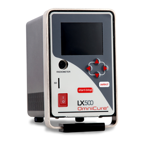
OmniCure® LX500 Series UV Curing Solutions UV LED Controller and Head Images Note: LX500-4 shown. Display Selection arrows Radiometer connection Select item highlighted in MicroSD display card slot connection for Start/stop Power exposure switch Power supply Connect PLC connection controller or door lock jumper Figure 1 UV LED Head Controller (front) -
Page 12: Installing The Hardware
OmniCure® LX500 Series UV Curing Solutions Installing the Hardware General Installation Determine the desired UV LED Head location and position based on the results of a series of testing and trials. Determine the working location of the Controller, ensuring access to the AC power source does not cause any possible obstruction with the power cable connection from the source to the controller. -
Page 13: Changing Lenses
OmniCure® LX500 Series UV Curing Solutions Changing Lenses Do not use any mechanical tool when removing or replacing the lens/housing. Hand tighten only, do not over tighten as this will make the assembly difficult to remove. The lens and housing are one subassembly. Do not attempt to remove the lens from the housing. Ensure the system is off and the head has cooled to room temperature before changing the lens. -
Page 14: Figure 5 Recommended Clamp Position
OmniCure® LX500 Series UV Curing Solutions Clamp Bottom of clamp should be between threaded housing crease and the reference line Figure 5 Recommended Clamp Position Figure 6 Typical Installation Applications Extension rod for use with standard optical fixtures Figure 7 Extension Rod Application http://www.excelitas.com/omnicure Excelitas Canada Inc. -
Page 15: Operation
Turn the Controller power switch to “ON” (refer to Figure The LCD screen will turn on and the Excelitas Technologies logo and the software version number will appear. A warning message may appear indicating that the Head is not in the same unit/head port position it was used in previously. -
Page 16: Understanding The Controller Display
OmniCure® LX500 Series UV Curing Solutions Understanding the Controller Display Status Bar The top left corner of the display shows the menu icon, which allows you to switch between screens. When nothing else on the screen is selected, the menu icon is. - Page 17 OmniCure® LX500 Series UV Curing Solutions Main Control Panel Displays upon start-up; shows current state of each connected UV LED Head (displays two or four channels depending on Controller model). The timer for each channel is how long (in seconds) the UV LED Head will remain on when an exposure is triggered.
- Page 18 OmniCure® LX500 Series UV Curing Solutions Settings Displays current system statistics. If necessary, use the arrow keys to select and change any field. Time and Date PLC Delay Timing and Head association – add a positive or negative delay to the Programmable Sync Out pin.
-
Page 19: Closed Loop Feedback
OmniCure® LX500 Series UV Curing Solutions Calibration Used to initiate and display the calibration process. Horizontal access is the intensity percentage setting, vertical access automatically scales and is the corresponding irradiance in W/cm2 or power in W. Section 8.5, ”Calibrating a UV LED Head”. - Page 20 OmniCure® LX500 Series UV Curing Solutions Running a sequence of exposures on one head, at varying times and intensities. Running a sequence of exposures on multiple heads, at varying times and intensities. Running parallel exposures on multiple heads, each can be at a different time and intensity. ...
- Page 21 OmniCure® LX500 Series UV Curing Solutions A signal on foot pedal #1 will run heads 1, 2 and 3 simultaneously. Note: “P” will run the head at the same time as the above step Note: If using the PLC Output, ensure that the head the PLC output is associated with is the first one listed in the parallel step.
-
Page 22: Running An Exposure From The Controller
OmniCure® LX500 Series UV Curing Solutions Running an Exposure from the Controller Set the timer and/or intensity on the Main Control Panel, or use the StepCure screen to set up multiple step exposure parameters. Refer to Section 6.4, “Defining Exposure Parameters”. Press Start/Stop on the front panel of the Controller to trigger an exposure. - Page 23 OmniCure® LX500 Series UV Curing Solutions Pin No. Signal Name Description Leaving signal floating will not trigger channel 2 / 4. Enable 4 Logic for the signal can be inverted in the Settings screen. This signal is edge triggered. The function of this signal can be modified in the StepCure screen.
-
Page 24: Using The Foot Pedal
OmniCure® LX500 Series UV Curing Solutions Pin No. Signal Name Description When the UV LED Head connected to channel 1-4 is off, SYNCOUT4 + pins are open. Logic for the signal can be inverted in the Settings screen. Programmable Sync When the UV LED head connected to channel 1 is on, pin Output + is active. - Page 25 OmniCure® LX500 Series UV Curing Solutions Use the StepCure screen (refer to Section 6.4 “Defining Exposure Parameters”) to set up the exposure parameters and, optionally, to override the default action described below. Press the foot pedal to trigger an exposure. All LEDs are in either count up or countdown mode: ...
-
Page 26: Troubleshooting
On any head level error condition, the alarm PLC output will be activated. The alarm output will clear when all active alarms have been cleared, this may require a power reset to clear the error. If problems persist beyond these troubleshooting points, please contact Excelitas Technologies Service Department (refer to Section 12, “Contact... -
Page 27: Error Codes
OmniCure® LX500 Series UV Curing Solutions Error Codes Error Description Solution The head(X) has exceeded the allowable operating Bit 1 Check position of clamp temperature. (error code will remain present until cleared, location on the head. Refer to however the head will be operative again when the Figure 5. -
Page 28: Table 2 Error Codes
OmniCure® LX500 Series UV Curing Solutions Table 2 Error Codes * X = LED Input Ch1, Ch2, Ch3, Ch4 http://www.excelitas.com/omnicure Excelitas Canada Inc. 2020 All rights reserved 035-xxxxxR, rev.1 035-00628R... -
Page 29: Care And Maintenance
OmniCure® LX500 Series UV Curing Solutions Care and Maintenance Note: Excelitas Technologies recommends incorporating the cleaning of the LX500 system into the user/operator cleaning and maintenance schedule. Cautions and Handling Caution: Routine maintenance should only be completed by qualified personnel to avoid risk of injury/electrical shock to the end user. -
Page 30: Cleaning The Led Head And Lens Assembly
Always use UV protective eyewear. The calibration process requires an Excelitas Technologies LS100 radiometer, or an LS100P radiometer. The LS100 is an irradiance only sensor that will calibrate the heads in W/cm2. The LS100P is a power only sensor that will calibrate the heads in W. -
Page 31: Viewing Log Files
OmniCure® LX500 Series UV Curing Solutions 2. Plug the LS100 or LS100P into the Radiometer connector on the front panel of the Controller (refer to Figure 3. Ensure the Door Jumper connector is securely connected the PLC connector. 4. Position the HeadLS100 over the LS100/LS100P sensor. 5. - Page 32 OmniCure® LX500 Series UV Curing Solutions Settings File The settings file consists of two parts, The first row is the titles for the general settings, followed by the actual settings. The third row is the header for the StepCure section, followed by the StepCure rows. StepCure can have a maximum of 32 rows.
- Page 33 OmniCure® LX500 Series UV Curing Solutions Item Description 3 – Foot Pedal 3 4 – Foot Pedal 4 5 – PLC Input 1 6 – PLC Input 2 7 – PLC Input 3 8 – PLC Input 4 9 – PC Repeat The number of times the program is to be repeated from 2>10.
- Page 34 OmniCure® LX500 Series UV Curing Solutions Item Description Date Date the calibration log entry was added. Time Time the calibration log entry was added. LX500 SN The serial number of the LX500 that the calibration was performed on. Hd # The head number that was calibrated.
-
Page 35: Technical Specifications
OmniCure® LX500 Series UV Curing Solutions Technical Specifications Environmental Conditions Operating Conditions Ambient Temperature 15ºC to 35ºC Altitude 2000m max. Atmospheric Pressure 700 to 1060 hPa Relative Humidity: 15% to 85% (non-condensing) Installation Category Pollution Degree Transport and Storage Conditions Temperature -10 to +60ºC Relative Humidity... -
Page 36: Uv Led Head Specifications
OmniCure® LX500 Series UV Curing Solutions Table 4: Controller Specifications UV LED Head Specifications Refer to OmniCure® LED Head Assembly Specification Guide 035-00638R for LED Head specifications. The peak wavelength of the UV LED Head +/- 5nm. The UV LED Head is capable of responding to PLC control signals in less than 1ms. The UV LED Head stability during close loop feedback is ±3% The UV LED Head calibration accuracy is ±5% or ±0.25W/cm2 whichever is greater for irradiance and ±5% or ±0.01W whichever is greater for power. -
Page 37: Regulatory Compliance
Operation of this equipment in a residential area is likely to cause harmful interference in which case the user will be required to correct the interference at their own expense. WARNING Changes or modifications not expressly approved by Excelitas Technologies could void the user’s authority to operate the equipment. 10.2 China RoHS The symbol above indicates a product does not contain any restricted substances. -
Page 38: Weee Directive
OmniCure® LX500 Series UV Curing Solutions 10.3 WEEE Directive The symbol above indicates that this product should not be disposed of along with municipal waste, that the product should be collected separately, and that a separate collection system exists for all products that contain this symbol within member states of the European Union. -
Page 39: Warranty
UV Curing Solutions 11 Warranty Excelitas Technologies warrants the original purchaser for a period of one (1) full year, calculated from the date of purchase, that the equipment sold is free from defects in material and workmanship. In the event of a claim under this warranty, the equipment is to be sent postage and carriage paid to the Excelitas Technologies Service Centre. -
Page 40: Contact Information
OmniCure® LX500 Series UV Curing Solutions 12 Contact Information Excelitas Canada Inc. 2260 Argentia Road Mississauga, Ontario L5N 6H7 CANADA Tel.: +1 905 821-2600 Toll: +1 800 668-8752 (USA and Canada) Fax: +1 905 821-2055 https://www.excelitas.com/product-category/omnicure-led-spot-uv-curing-systems-and-accessories https://www.excelitas.com/ox_service_request_form https://www.excelitas.com/omnicure-x-cite-inquiries Technical Assistance: techsupport@excelitas.com https://www.excelitas.com/ox_service_request_form For a complete listing of Authorized OmniCure Distributors and Service Centres, please go to...
Need help?
Do you have a question about the OmniCure LX500 Series and is the answer not in the manual?
Questions and answers