Advertisement
Quick Links
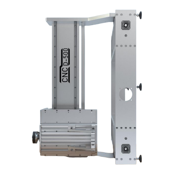
CNC D-500 Build Instructions V1.0
http://www.ukcnc.net
Please make sure you have checked the Plate Checklist and that all the
parts have been received. Before proceeding with these build
instructions.
Unpack the ballscrews and the FK12/FF12 bearing sets.
Be careful to not loose the little circlips that are packed with the FF12
bearings.
To protect the parts you will find that they are covered in a light oil and
it is worth wiping this all off before starting to assemble. Also wearing
Advertisement

Related Manuals for CNC Design D-500


Summary of Contents for CNC Design D-500
- Page 1 CNC D-500 Build Instructions V1.0 http://www.ukcnc.net Please make sure you have checked the Plate Checklist and that all the parts have been received. Before proceeding with these build instructions. Unpack the ballscrews and the FK12/FF12 bearing sets. Be careful to not loose the little circlips that are packed with the FF12 bearings.
- Page 2 rubber nitrate gloves to protect your hands from this thin oil penetrating your skin is advised. Slide the bearings over the end of each ballscrew. If a little bit tight then gently tap on with a tube that matches the inner race. Do not hammer the whole bearing as you could damage it.
- Page 3 It is up to you when you apply grease, but can be easier as you assemble or you can do it at the end of the build. We always find it easier to place the grease into a syringe first and then squeeze some grease into the ballnut until it comes out the sides.
- Page 4 Get the parts shown above ready for assembly. Attach the Z-Axis ballnut block on to the ballscrew with the M5x25mm screws hand tight.
- Page 5 Slide the ballscrew through the DC-Plate8 and slide on the FK12 spacer. Slide the FK12 bearing on to the ballscrew.
- Page 6 Slide on the second FK12 spacer. Grip the ballscrew using a wrench and a rag to protect the thread. Screw on the locking nut.
- Page 7 Tighten off the locking nut with a spanner. On the locking nut is a small grub screw that will need tightening off.
- Page 8 Insert the M4 x 16mm screws and tighten off. Get the parts shown above ready for assembly.
- Page 9 Attach the Y-Axis ballnut blocks on to the ballscrews with the M5 x 25mm screws hand tight.
- Page 10 Get the parts shown above ready for assembly. Making sure the ballscrew is threaded through DC-Plate14, slide on the FK12 spacer.
- Page 11 Slide the FK12 bearing on to the ballscrew. Slide on the second FK12 spacer.
- Page 12 Grip the ballscrew using a wrench and a rag to protect the thread. Screw on the locking nut and tighten off with the spanner. On the locking nut is a small grub screw that will need tightening off. Do the same assembly for the other side also.
- Page 13 On both sides, insert the M4 x 16mm screws and tighten off. Get the parts shown above ready for assembly.
- Page 14 Attach the X-Axis ballnut block DC-Plate4 on to the ballscrew with the M5x25mm screws hand tight. Making sure the ballscrew is threaded through DC-Plate11, slide on the FK12 spacer.
- Page 15 Slide the FK12 bearing on to the ballscrew. Slide on the second FK12 spacer.
- Page 16 Grip the ballscrew using a wrench and a rag to protect the thread. Screw on the locking nut and tighten off with a spanner. On the locking nut is a small grub screw that will need tightening off.
- Page 17 Insert the M4 x 16mm screws and tighten off into DC-Plate11. Repeat this for the other side. All the ballscrew assemblies are now ready for the build.
- Page 18 Get the parts shown above ready for assembly. First get the Left side base parts together...
- Page 19 Insert the M5 x 25mm screws hand tight for now. Again, insert the M5 x 25mm screws hand tight for now.
- Page 20 Repeat the same for the Right hand side.
- Page 21 The left and right sides should now look as shown in the picture above.
- Page 22 Get the parts shown above ready for assembly.
- Page 23 Fit the FK06 bearings to both sides of the bottom front plate. Insert the FK06 bearing and screw in the M4 x 12mm screws, leaving them hand tight so there is a little bit of movement.
- Page 24 Note the two holes in the bottom of the plate, these will face downwards when assembled. Offer up DC-Plate29 to the side assemblies and align with the ballscrew bearings. Insert the M6 x 25mm screws and do up hand tight.
- Page 25 Get the parts shown above ready for assembly. Slide the coupler onto the ballscrew and do not tighten up. Fix the motor in place with the M5 x 12mm screws.
- Page 26 Do the same for the other side Slide the coupler onto the ballscrew and do not tighten up. Fix the motor in place with the M5 x 12mm screws. This is how it should look when both motors are attached.
- Page 27 Note the M4 holes in the bottom of the plate, these will face downwards when assembled. Insert the M6 x 25mm screws hand tight.
- Page 28 The reason we put all the screws in hand tight is so we can now easily square up the frame. Make sure the frame is on a flat even surface and then tighten off the M6 screws first on the front and back plate, making sure the other plates are nice and square to the edges of other plates.
- Page 29 Get the parts shown above ready for assembly. We would recommend having the nipples of the bearing facing outwards on each rails and have supplied a plastic insert that will allow you to achieve this if needed. First bring the bearing gently to the end of the rail and offer up the insert so it lines up with the bearing.
- Page 30 Next slide the bearing off the rail and onto the insert. Finally turn the bearing around and slide back on gently making sure the insert is lined up the rail.
- Page 31 Bolt the rails onto both of the base sides, doing up the bolts hand tight. Get the parts shown above ready for assembly.
- Page 32 Place the upright on to the template and insert the M4 x 20mm screws. Tighten these off making sure the uprights are square. Do this for the other side also. With the template still in place, first tighten off the front M4 rail bolts.
- Page 33 Slide the arm now to the back of the machine and again with the template in place, tighten off the M4 rail bolts. Now slide the arm gradually along, tightening off all the remaining M4 screws. You will find the arm will gradually lift up above the template as you go along and the spacing should be the same along the travel of the rail.
- Page 34 The frame should look like the picture above at this point in the assembly.
- Page 35 Get the parts shown above ready for assembly. Turn the machine now on its side. Screw in each bolt as tight as they will go in and make sure all of them are the same depth.
- Page 36 You will find that you probably need to tap each foot on with a hammer if they do not push on, as they are a very tight fit. Place the rubber end cap on to each of the feet.
- Page 37 Make sure they are nice and even with each of the feet. All six of the feet fitted as shown in picture above.
- Page 38 Bring the machine back down so each of the feet are now sitting on the bench.
- Page 39 Get the parts shown above ready for assembly. On the right side DC-Plate31 on the machine insert the FK06 bearing holder and tighten off the M4 screws.
- Page 40 Get the parts shown above ready for assembly. Attach the two plates together using the M4 x 8mm screws. The word TOP in marked on the DC-Plate17 and should be facing downwards on the bench.
- Page 41 Assemble the two plates as shown in the picture above using the M5 x 25mm bolts. These will bolt down into the plate on the ballscrew assembly and also DC-Plate10 Make sure is nice and square as you tighten off all the screws.
- Page 42 Slide on the coupler.
- Page 43 Fix the motor in place with the M5 x 12mm screws. Note the position of the motor, so the connector blocks are facing the same way as the DC- Plate34...
- Page 44 Tighten off the coupler. Get the X-Axis assembly ready to now fit on to the Y-Axis uprights.
- Page 45 This will take two people, one to hold the X-Axis assembly and the other to insert the M6 x 25mm screws. Hand tighten these bolts at this stage and do not do up tight.
- Page 46 Do the same for the other side, inserting the M6 x 25mm screws hand tight.
- Page 47 Get the parts shown above ready for assembly.
- Page 48 Insert and tighten off the M5 x 16mm screws Attach the assembly to the X-Axis ballnut block with the M6 X 16mm screws and tighten off.
- Page 49 Get the parts shown above ready for assembly. As previously shown, turn the carriages around if needed using the plastic insert. Attach the rails with the M4 x 16mm screws hand tight.
- Page 50 Insert the M6 z 25mm screws hand tight.
- Page 51 Insert the M6 x 25mm bolts and do hand tight.
- Page 52 Now tighten off the M5 and M6 bolts fully.
- Page 53 Get the parts shown above ready for assembly. Insert the FK06 bearing holder and tighten off the M4 x 12mm screws.
- Page 54 Attach the rails with the M4 x 16mm screws hand tight. As previously shown, turn the carriages around if needed using the plastic insert.
- Page 55 Attach DC-Plate8 to DC-Plate6 with the M5 x 16mm screws and tighten off.
- Page 56 Attach DC-Plate9 to DC-Plate6 with the M5 x 16mm screws and tighten off.
- Page 57 Place DC-Plate32 spacer blocks onto each rail carriage.
- Page 58 Align DC-Plate1 with each carriage and insert the M4 x 30mm screws. Tighten off each bolt making sire the edge of DC-Plate1 is square with the edge of DC-Plate9...
- Page 59 Gently slide DC-Plate1 up just enough so you can tighten off the first screws on the rails. Now slide DC-Plate1 up and tighten off the other top screws. Check now that when DC-Plate1 slides back and forth that it is square.
- Page 60 Now tighten off the second screw on the rail at the bottom. Slide DC-Plate1 back down and tighten off the screw shown in picture above.
- Page 61 Slide DC-Plate1 to the middle of the rails, so you can access and tighten off the screw. Flip the Z-Axis assembly around and Slide DC-Plate1 to the middle of the rails, so you can access and tighten off the final screw.
- Page 62 Attach the DC-Plate1 to the Z-Axis ballnut block with the M6 x 16mm screws. Get the parts shown above ready for assembly.
- Page 63 Attach the DC-Plate33 brackets with the M5 x 12mm screws. In the picture above you can see the DC-Plate33 brackets in place.
- Page 64 You can now tighten off the M6 bolts in the ballnut assembly by accessing them through the DC-Plate6 cut outs. You can also access the M6 screws from behind DC-Plate6 to tighten off.
- Page 65 Next is to attach the Z-Axis assembly to the X-Axis bearings. Make the sire the plate is lined up as shown in the picture above and attach the Z-Axis assembly to the carriages of the X-Axis using the M4 x 12mm screws.
- Page 66 Do this for all 16 M4 x 12mm screws. Make sure the plate is nice and square as you tighten them off.
- Page 67 Slide the Z-Axis assembly to the left hand side of the machine and tighten off the first M4 bolt on the bottom rail. Slide the Z-Axis assembly to the right hand side of the machine and tighten off the first M4 bolt on the bottom rail.
- Page 68 Now sliding the Z-Axis assembly from right to left, do up each M4 screw on the rail as you move along. Now do the same for the top rail. Slide the Z-Axis assembly to the left hand side of the machine and tighten off the first M4 bolt on the top rail.
- Page 69 Slide the Z-Axis assembly to the right hand side of the machine and tighten off the first M4 bolt on the top rail. As before slide the Z-Axis assembly from right to left, do up each M4 screw on the top rail as you move along.
- Page 70 Now we can alight the X-Axis plate that is attached to the rails onto the assembly of the X-Axis ballscrew. Insert the two top M5 x 16mm screws and do up along the top. Insert the two top M5 x 16mm screws and do up along the bottom.
- Page 71 To tighten off the top M5 x 16mm screw that cannot be reached from behind, use the hole on the front of the plate. To tighten off the bottom M5 x 16mm screw that cannot be reached from behind, use the hole on the front of the plate.
- Page 72 Tighten off the M5 screws on the ballnut.
- Page 73 It should now look like the picture above at this stage of assembly.
- Page 74 Get the parts shown above ready for assembly.
- Page 75 Slide the DC-Plate7 into the Z-Axis assembly and tighten off.
- Page 76 Slide the second DC-Plate7 into the Z-Axis assembly and tighten off.
- Page 77 Get the parts shown above ready for assembly.
- Page 78 Slide the T-nuts into the profile as shown in the picture above. Fix the profile onto the Z-Axis assembly using the M5 x 20mm screws and tighten off.
- Page 79 Get the parts shown above ready for assembly.
- Page 80 Attach the DC-Plate24 and DC-Plate25 to the sides of DC-Plate27 with the M5 x 16mm screws. Also attach the DC-Plate26 brackets to DC-Plate24 and DC-Plate25 using the M5 x 16mm screws.
- Page 81 Attach the spindle holder to the profile with the M8 bolts and T-nuts.
- Page 82 Get the parts shown above ready for assembly. Attach the motor to DC-Plate5 as shown in the picture above with the M5 x 12mm screws and tighten off.
- Page 83 Place the motor and bracket inside the top of the Z-Axis assembly and screw in with the M5 x 30mm screws hand tight.
- Page 84 Slide on the two pulleys and belt as shown in the picture above. Adjust the tension on the belt so it is nice and tight and then tighten off the M5 x 30mm screws.
- Page 85 Tighten off the bolts on both of the pulleys, making sure they are level first. Attach the Y-Axis upright on the left-hand side with the M5 x 30mm screws.
- Page 86 Rotate the ballscrew so the ballnut block is level with the right-hand side upright. Attach the Y-Axis upright on the right-hand side with the M5 x 30mm screws. Tighten off the right-hand side M5 screws on the ballnut.
- Page 87 Tighten off the left-hand side M5 screws on the ballnut. Tighten off the coupler bolts on the left-hand side of the Y-Axis.
- Page 88 Tighten off the coupler bolts on the right-hand side of the Y-Axis.
- Page 89 As a final check, go around the frame and make sure all the screws are nice and tight and everything is square. Also if you did not apply grease while building the frame, apply it now to all the rails and ballscrews. Your frame is now complete and ready for wiring !
Need help?
Do you have a question about the D-500 and is the answer not in the manual?
Questions and answers