
Subscribe to Our Youtube Channel
Summary of Contents for MPI Ultrasonic generator
- Page 1 20 to 40 kHz – 2000W (other frequency ranges available) ULTRASONIC GENERATOR – Manual...
-
Page 2: Table Of Contents
CONTENTS CONTENTS ................................2 INTRODUCTION ..............................4 GENERAL INFORMATION ..........................4 SAFETY INSTRUCTIONS ..........................5 GENERAL VIEW..............................7 DIMENSIONS ..............................8 INSTALLATION & ENVIRONMENT ......................9 POWER SUPPLY ..............................9 HF CONNECTOR ...............................10 25-PIN DSUB I/O SOCKET .........................11 WIRING FOR START ............................1 INTERFACE SOCKET RS485 MODBUS - RJ 45 CONNECTOR: ............11 OPERATOR ELEMENTS AND DISPLAY ON THE FRONT PANEL............4 MAIN STARTING WINDOW ...........................4 TIME WINDOW ..............................5... - Page 3 WRITE TO MEMORY WINDOW ........................10 MODBUS COMMUNICATION PROTOCOL ....................11 ERROR MESSAGES AND TROUBLESHOOTING..................13 MAINTENANCE..............................15 SPECIFICATIONS: ............................15 WARRANTY ...............................16 SPARE PARTS ..............................16 SERVICE HOTLINE ............................16...
-
Page 4: Introduction
Failure to comply with this will result in a loss of warranty rights. General information This ultrasonic generator is a device which is used for ultrasonic plastic- and metal-welding applications as well as for different special applications such as: Sieving, atomizing, etc. -
Page 5: Safety Instructions
Inspection or diagnostic work inside the device may only be carried out to the extent described and, as with the electrical connection should only be performed by skilled personnel. When performing such work, the ultrasonic generator must be completely disconnected from the main power source. (unplug the mains connection). - Page 6 Inputs or outputs that are used for controlling or monitoring purposes should be twisted and shielded. The device must not be in close proximity to electrically charged components or cables. The shielding should be connected to the generator‘s earth on one side of the generator. Attention: All connections for the signal or control lines are galvanically connected to the generator.
-
Page 7: General View
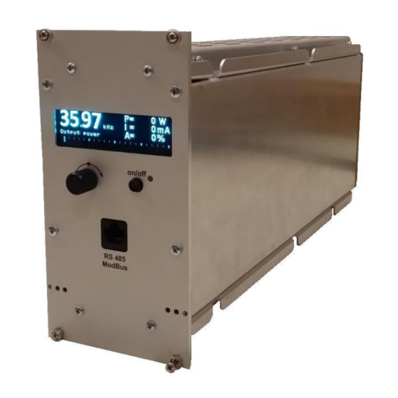
GENERAL VIEW Front view Back view Display high resolution – 72x20mm Knob encoder Bi color LED Command for US ON RJ45 connector Main Switch ON/OFF Power socket 210-250V 25-POLE DSUB I/O SOCKET HF Lemo Plug... -
Page 8: Dimensions
DIMENSIONS 89mm 154.5mm 342mm... -
Page 9: Installation & Environment
Power supply The ultrasonic generator draws its power (210-250VAC/50-80Hz) via the connection cable with Power socket. It has an internal main fuse (10 AF). If you need to change the fuses, unscrew the cover of the housing. -
Page 10: Hf Connector
HF connector HF OUTPUT HF connector is Lemo connector Can be modified according to customer request. • Output voltage could be between 600V and 1200V AC. • Only use cables specified by the manufacturer. • Use only shielded transducer connection cables. -
Page 11: 25-Pin Dsub I/O Socket
25-pin DSUB I/O socket Signal Signal Direction Description Number level +12V Output +12Vdc Supply voltage for external use 100mA max Input and output Relay HF-DA. Contact is closed Up to 14,2 HF/RF when ultrasonic voltage is emitted. 24Vdc (seeFig.3) Input and output Relay Error. Contact is closed Up to 15,3 Error... - Page 12 Example of external connections Generator: 25-pole interface Error HF-RF Relay Relay +12V -OUT Error HF/RF HF/RF Amplitude Error REM+ Power Temp REMG Max. 0-10V 0-10V 0-10V 100mA +24V +10V Temp. sensor Error...
-
Page 13: Wiring For Start
Wiring for start using a signal 12 V The generator has internal supply of +12V on pin 1. The 4 pins (1-17-5-18) have to be connected. Using an external +24V If user wants to use +24V, it must use an external supply. - Page 14 Start with PLC +24V output Connection of HF-RF +24V input output...
- Page 15 Connection of Pneumatic valve Relay with coil resistance ~ 1.5kΩ Or Solid State Relay (SSR) Cf page 36 for parameters of HF-RF.
-
Page 16: Operator Elements And Display On The Front Panel
Operator elements and display on the front panel Button ON/OFF Bicolour LED Rotary Encoder & Push Button Bicolour LED: Lights up green when generator is switched on and works properly Lights up in the event of an error ON/OFF button: The functionality of the button could be selected from System window (6) or in LabView software PROPERTIES tab. -
Page 17: Time Window
Power window Power – setting for maximal power (in W) Amplitude – setting for maximal amplitude (in % where 100% = 1000V) Frequency – setting for starting frequency (in kHz) P – Actual Output Power Value (in Watts) I – Actual Output current through the transducer (in mA) Time window These are welding regime settings. -
Page 18: Peak Power Window
Peak power window These are welding regime settings. Welding by peak power: Peak Power – setting of the peak power (in W). If the setting is different from 0 and the generator reaches the set value of the peak power, the Welding Time(see page 23-24) automatically stops. - Page 19 START Button – setting the functionality of the button There are 4 options: OFF – the button is off. Any action on start button will not start the generator. Generator can only be started by remote start (on 25 pins connector). PUSH –...
- Page 20 LATCH- the generator starts with a start and stops with a second pulse pushing the button once the generator starts, pushing the button again the generator stops. To START generator : either by start button on front of generator or by remote start on 25 pins connector (see page 13 for remote start) To STOP generator : either press the start button at front of generator or send signal on remote start on 25 pins connector (see page 13 for remote start)
- Page 21 TRIGGER – this mode must be used if time, power or energy parameters are set To START generator : either by start button on front of generator or by remote start on 25 pins connector (see page 13 for remote start) To STOP generator : either press the start button at front of generator or send signal on remote start on 25 pins connector (see page 13 for remote start)
-
Page 22: Write To Memory Window
Write to memory window This window appears when you PRESS AND HOLD the Rotary Encoder for 2 sec. - Page 23 Interface socket RS485 ModBus - RJ 45 CONNECTOR: PINS DESCRIPTION Output 12 V DC(max 100mA) Output 12 V DC(max 100mA)
-
Page 24: Modbus Communication Protocol
MODBUS COMMUNICATION PROTOCOL All generators are Modbus devices. Below is the table of Modbus memory. Connection You can use the front RJ45 connector or the back 25 pins socket to connect the generator using Modbus. do not forget to connect the GND About Shield cables, it must be connected only on one side. - Page 25 Bus description bus address of the device (1-255) – selecting via LCD panel transmission speed – selecting via LCD panel no parity check the number of Data-bits is RTU 8 Data bits the number of STOP-bits is 2 STO-bit important remarks for operation in the Master/Slave system : The bus address must be differently adjusted for each device !! Transmission mode, baud rate and parity must be identical...
- Page 26 register parameter … BEAT counter Start frequency 10 Hz Output power set point Span set point Spare Regulator Ki Regulator Kv I max Modbus address Command word bit field RESET START STOP SCAN WRITE TEST Spare Spare 0x36 0x37 ASCII 0x32 over 0x33 over 0x34...
- Page 27 SP amplitude Current scale External temperature °C x 10 Nominal amplitude Relay status bit field Relay HF/RF Relay Error Spare Phase Peak power Peak power plus Peak power minus Energy Energy plus Energy minus Time ms x 10 Time plus ms x 10 Time minus ms x 10...
- Page 28 START modes bit field HOT START AUTOTUNE RAMP Amplitude ……… ……… Scan data ……….
- Page 29 The following MODBUS-control commands are supported : Description Function code Read register 0x03 Write Register 0x10 Example to READ register We want to read the values of Last peak power, last energy and last welding time. Query 06 03 002A 0003 25B4 Adress of generator (06 hex = address 6 ) 0x06 command to read the register...
- Page 30 Example to write register Query 11 10 0001 0002 04 000A 0102 C6F0 Slave adress (11 hex = address 17) 0x11 command to write the register 0x10 The Data Address of the first register requested. 0x00 ( 002A hex = 42 ,) 0x01 The total number of registers to write 0x00...
- Page 31 SETTING THE SOFTWARE LABVIEW The generator has a standard communication interface ModBus RTU over RS 485. To connect to a PC you should use MPI adapter USB or RS 232 to RS 485 optically isolated. ADDR1 ADDR2 ADDR32 USB or RS232...
- Page 32 CONTROL TAB On this tab, we can set : - start frequency - span - power set point = maximum power that we want the generator delivers - phase = let at 20. If higher, generator will work closer to serial resonance, if lower closer to parallel resonance.
- Page 33 we can save and import saved parameters from computer...
- Page 34 WELDING TAB On this tab we can adjust the welding parameters such time, power and energy. We can adjust also the cycle parameters as DELAY – HOLDING TIME – AFTERBURST TIME. We can also check that Time, power and energy are inside a window. For example : - We weld by time : 1.2s We know that to have a good welding the energy used is between 120J and 155J.
- Page 35 PROPERTIES TAB area 1 The matrix with statistics of every weld process can be selected and exported to excel file – as it is on the picture. We can export on excel file all parameters of all cycles. Must be connected to a computer. area 2 DC power scale factor = do not modify nominal power = maximum power that we want the generator delivers.
- Page 36 HF Relay mode We can select when the internal relay inside the generator is closed. On generator On Process On solenoid Delay Welding time Hold time afterburst The cross ‘X’ indicates when the relay is closed during the cycle. example with vertical press : We choose to weld by time.
- Page 37 SCAN TAB After adjusting parameters on control tab, we must SCAN the transducer or horn to let the generator to calibrate itself. Span Fstart...
- Page 38 COMM TAB This tab is used to connect the software to the generator. Connect the generator to Labview software. 1. Select the exact COM port(1) to which the adapter is connected from the drop down menu. 2. Once connected, the light become green...
- Page 39 OSI TAB An oscilloscope allows us to follow the following parameters during welding cycle: frequency output current phase amplitude power regulator phase : how fast generator is shifting down the frequency from Fstart, looking for the selected Phase value. regulator voltage : combines regulation of output voltage, output current, Power. If one of them exceeded the selected value –...
- Page 40 EXAMPLE HOW TO START WITH LABVIEW 1. Connect the generator to LAbview (COMM TAB) 2. go to control tab and adjust : Fstart = 37kHz if generator 35kHz Span = 4kHz power set point = 2kW if we want 2kW on generator phase = 20 Imax = 2A if generator 2kW amplitude = 50%...
-
Page 41: Error Messages And Troubleshooting
ERROR MESSAGES AND TROUBLESHOOTING When error event occurs the bicolor LED will ligh up in red. The error message will appear over the dynamic bar graph. If you want to see it properly you need to press the rotary encoder once, to move to next window of the display (Power window), where on the last row an error message will be displayed. - Page 42 · The cable between the generator and transducer is broken or just disconnected. Possible causes · Starting frequency selected is too HIGH · Starting frequency selected may be too LOW OVERVOLTAGE · Rescan and re-adjust the generator How to fix ·...
-
Page 43: Maintenance
How to fix · Check the welding process for lapses MAINTENANCE The ultrasonic generator does not need special maintenance. Dust and dirt should be removed regularly using a damp cloth. ATTENTION: • Do not use aggressive cleaners! • Not suitable for ultrasonic cleaning... -
Page 44: Warranty
WARRANTY The length and coverage of the warranty can be found in the terms of delivery as part of the general terms and conditions (valid at the time of purchase) or in the sales contract / order confirmation, should any special agreements have been made.
Need help?
Do you have a question about the Ultrasonic generator and is the answer not in the manual?
Questions and answers