Table of Contents
Advertisement
Quick Links
Advertisement
Table of Contents

Related Manuals for Comelit ILS-2


Summary of Contents for Comelit ILS-2
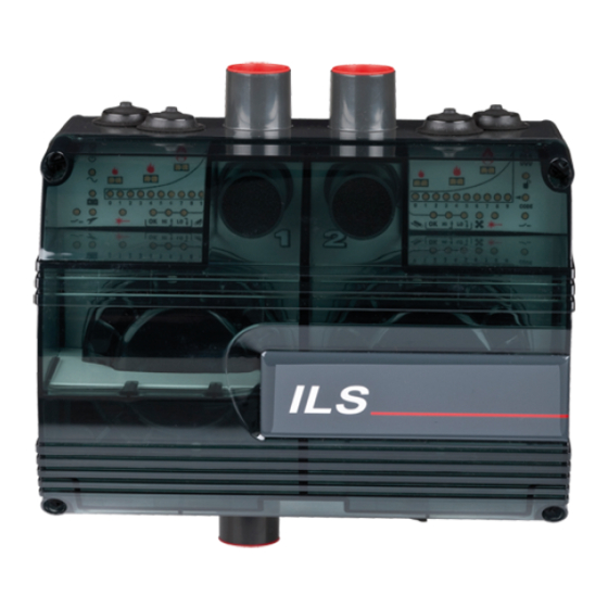
- Page 1 ASPIRATING SMOKE DETECTOR, 1 ZONE, 2 DETECTORS ILS-2...
- Page 2 DISCLAIMER The content of this document is provided “as seen”. No responsibility is taken and no guarantee (express or implied) is made in terms of the complete nature, accuracy or reliability of the content of this document. The manufacturer reserves the right to make changes to the design or the specifications, without any obligation and without prior notice.
-
Page 3: Table Of Contents
Summary 1 Introduction ................................4 2 Installing the detector .............................. 4 3 Terminal block connections ............................. 4 3.1 Connection to external devices ......................... 5 4 Installing the piping ..............................7 4.1 Piping specifications ............................7 4.2 Fixing ................................. 7 4.3 Bends ................................. 7 4.4 End caps ................................ -
Page 4: Introduction
1 Introduction The ILS-2 System is an aspirating detector which uses a network of sampling pipes to channel air to the two high- sensitivity point detectors housed inside the casing of the main detector. The use of a network of pipes offers a larger area of protection coverage in comparison to traditional point detectors. -
Page 5: Connection To External Devices
Figure 3-2: Ferrite core ILS-2 must be powered by means of a 24 Vdc power supply unit with EN54-4 approval. The power supply must be connected using the BATTERY terminals on board the terminal block, observing the correct polarity. The minimum recommended size is 16 x 0.25 mm (18 AWG), or greater if the power supply unit is further than 5 m... - Page 6 3.1.5 External Reset The application of a voltage of +24 Vdc to these terminals triggers a reset of all fault and alarm events present.
-
Page 7: Installing The Piping
(inspectable). IMPORTANT note: the ILS-2 pipe inlets are tapered so as to allow “push-fit” coupling of the piping coming from the site. The end of the inlet pipe must be cut cleanly so as to allow airtight coupling with the tapered inlet. -
Page 8: End Caps
The air outlet must be positioned with care, to ensure it is not obstructed accidentally. 4.7 Filters Figure 4-3: Filters at the inlet of the ILS-2 detector The sampled air is passed through a filter (code: 02-FL53) before it enters the optical detection... -
Page 9: Standard Pipe Configurations
4.8 Standard pipe configurations USB port Type “B” Figure 4-4: Standard configuration for ILS-2 The double pipe configuration can have a maximum length of 200 m (max. 100 m per incoming pipe), with up to 18 x 3 mm sampling holes and a 6 mm end cap hole for each pipe. - Page 10 6 Setup 6.1 Display functions ALERT (Alert) ACTION (Pre-alarm) LED BAR CHART (Smoke level and Fan speed) FIRE (Fire alarm) SMOKE DETECTOR FAULT (detector fault - 1 per detector) AIRFLOW OK - HIGH AIRFLOW - LOW AIRFLOW ISOLATE (Disabled=relays not active) POWER ON (Power supply present) FAN FAULT (Fan fault) GENERAL FAULT (General fault)
-
Page 11: User Functions
6.2 User functions Figure 6-1: Programming buttons Press and hold the SELECT and CHANGE buttons simultaneously until you hear the initialisation beep. Press and release the SELECT button to move through the various configuration steps. Press and release the CHANGE button to change the current parameter. The corresponding LED will flash continuously to indicate the active function in that step. - Page 12 Table 6-1: User functions for ILS-2 FUNCTION DISPLAY VALUE NOTES RECOMMENDE Reset the unit The RESET LED flashes Press CHANGE to reset the outputs The ISOLATE LED is lit Isolate the relay outputs steadily Press CHANGE to Isolate or when the system is...
- Page 13 sensors.
-
Page 14: Setup Notes
Notes: Mode 3 is not permitted in installations which require VdS approval. ILS-2 is supplied in standard mode 1. If required jointly, the second detector will be supplied in Mode 2. If the unit only houses one detector and mode 3 is programmed, a Detector Fault will be signalled. - Page 15 Table 6-2: Flow Fault delay times Bar chart Flow Fault ind. Flow Fault status delay (seconds) exit delay (seconds) Notes: Timings are approximate. 6.3.3 Flow Sensitivity This setting determines the sensitivity of the unit in detecting blocked sampling holes or broken pipes. The default flow sensitivity value of 9, which corresponds to a change in volumetric airflow of ±...
-
Page 16: Testing
7 Testing Note: the system checks should only be carried out by authorised personnel. Before undertaking any testing, make sure that the proper authorities have been informed and that signals to the monitoring and signalling control panel have been disabled, in order to prevent unwanted alarms. 7.1 Point detectors With the unit powered up and plastic top cover removed, detector operation can be tested using a low concentration smoke source or aerosol spray. -
Page 17: Maintenance
8 Maintenance With normal use, the filter element will eventually become contaminated with dust particles contained in the extracted air. It is recommended that the filter element (code 02-FL53) is replaced and detectors cleaned every 6 months (more frequently for dirty environments). Note: maintenance should be performed by authorised personnel. -
Page 18: En54-20 Sensitivity Classes
9 EN54-20 Sensitivity classes The detectors used in ILS-2 have been independently tested and approved for use in EN54-20 certified Class A, B or C installations. The following information will show the requirements for compliance with the abovementioned standard. Table 9-1: Sensitivity and maximum number of holes vs Class EN54-20... -
Page 19: Troubleshooting
10 Troubleshooting PROBLEM POSSIBLE SOLUTION Power supply LED flashes Make sure the power supply voltage is between 18 - 30 Vdc. No LEDs lit on display and Make sure the 24 Vdc power supply is present and that the +/- polarities have been fan NOT working observed. -
Page 20: Specifications
11 Specifications Table 11-1: General Specifications, ILS-2 Number of detectors 1 or 2, laser point technology Filter Single-stage Airflow sensors Thermal devices - High and Low thresholds. 10-LED bar chart Power supply voltage 18 - 30 VDC (24 VDC rated)
Need help?
Do you have a question about the ILS-2 and is the answer not in the manual?
Questions and answers