Table of Contents
Advertisement
Quick Links
Advertisement
Table of Contents

Related Manuals for Metrohm 786 Swing Head


Summary of Contents for Metrohm 786 Swing Head
- Page 1 786 Swing Head Manual 8.786.8001EN / 2019-09-25...
- Page 3 Metrohm AG CH-9100 Herisau Switzerland Phone +41 71 353 85 85 Fax +41 71 353 89 01 info@metrohm.com www.metrohm.com 786 Swing Head Manual 8.786.8001EN / 2019-09-25...
- Page 4 Technical Communication Metrohm AG CH-9100 Herisau techcom@metrohm.com This documentation is protected by copyright. All rights reserved. This documentation has been prepared with great care. However, errors can never be entirely ruled out. Please send comments regarding possible errors to the address above.
-
Page 5: Table Of Contents
4 Handling and maintenance 5 Troubleshooting Robotic arm ................. 21 6 Appendix Robotic arms ............... 23 6.1.1 Robotic arms for titration ............23 6.1.2 Robotic arms for sample preparation ........25 6.1.3 Robotic arms for special applications ........26 ■■■■■■■■ 786 Swing Head... - Page 6 ■■■■■■■■■■■■■■■■■■■■■■ Table of contents 7 Technical specifications 786 Swing Head ..............28 Supply connection .............. 28 Ambient temperature ............28 Reference conditions ............28 Dimensions ................29 8 Accessories Index ■■■■■■■■ 786 Swing Head...
- Page 7 ■■■■■■■■■■■■■■■■■■■■■■ Table of figures Table of figures Figure 1 Front 786 Swing Head ............... 6 Figure 2 Underside 786 Swing Head ............... 7 Figure 3 Connecting Swing Head ..............9 Figure 4 Mounting the tower extension ............10 Figure 5 Mounting the Swing Head to the tower extension ......
-
Page 9: Introduction
1 Introduction Instrument description The 786 Swing Head is an auxiliary drive for the Sample Processors from Metrohm, e.g. the 815 USB Robotic Sample Processor XL. It extends the capabilities of these automation systems to include the possibility of mov- ing precisely to any given position on a sample rack. -
Page 10: Intended Use
■■■■■■■■■■■■■■■■■■■■■■ 1.3 Intended use Intended use The 786 Swing Head is designed for usage in an automation system in analytical laboratories. It is not suitable for usage in biochemical, biologi- cal or medical environments in its basic equipment version. This instrument is suitable for transferring chemicals and flammable sol- vents. -
Page 11: Safety Instructions
The electrical safety when working with the instrument is ensured as part of the international standard IEC 61010. WARNING Only personnel qualified by Metrohm are authorized to carry out service work on electronic components. WARNING Never open the housing of the instrument. The instrument could be damaged by this. -
Page 12: Tubing And Capillary Connections
Personnel safety WARNING Wear protective goggles and working clothes suitable for laboratory work while operating the 786 Swing Head. It is also advisable to wear gloves when caustic liquids are used or in situations where glass vessels could break. WARNING Always install the safety shield supplied with the equipment before using the instrument for the first time. -
Page 13: Flammable Solvents And Chemicals
WARNING The 786 Swing Head is not suitable for utilization in biochemical, bio- logical or medical environments in its basic equipment version. Appropriate protective measures must be implemented in the event that potentially infectious samples or reagents are being processed. -
Page 14: Overview Of The Instrument
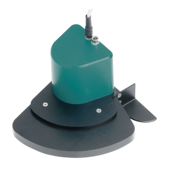
■■■■■■■■■■■■■■■■■■■■■■ 2 Overview of the instrument Figure 1 Front 786 Swing Head Connection cable Connector for beaker sensor Housing Fastening plate Guide slot For the robotic arm reinforcement. ■■■■■■■■ 786 Swing Head... -
Page 15: Figure 2 Underside 786 Swing Head
■■■■■■■■■■■■■■■■■■■■■■ 2 Overview of the instrument Figure 2 Underside 786 Swing Head Drive disc Swing axis Drive pin M2 bore holes For fastening a robotic arm. ■■■■■■■■ 786 Swing Head... -
Page 16: Installation
1 Loosen the screws of the holder on both sides. 2 Loosen and remove the holder from the holder plate of the guide chain. Use the hexagon key provided. The screws will be needed again later. ■■■■■■■■ 786 Swing Head... -
Page 17: Figure 3 Connecting Swing Head
1 Screw the Swing Head tightly to the holder plate of the guide chain. 2 Clamp the Swing Head between the guide jaws. 3 Screw the Swing Head to the guide jaws with the screws previously loosened. ■■■■■■■■ 786 Swing Head... -
Page 18: Figure 4 Mounting The Tower Extension
1 Fasten the tower extension to the lift guide of the Sample Processor in accordance with the following illustration and fix it in place with the screws provided. Figure 4 Mounting the tower extension 2 Mount the Swing Head to the holder plate of the guide chain. ■■■■■■■■ 786 Swing Head... -
Page 19: Guide Chain For Cables And Tubing
Insert a screwdriver into the groove located on the side of a chain ■ link. Loosen the clip with a forceful leverage movement. ■ Pull the clip out of the chain by hand. ■ Repeat the above actions for each chain link. ■ ■■■■■■■■ 786 Swing Head... -
Page 20: Mounting The Robotic Arm Reinforcement
The reinforcement provides the robotic arm with stable resistance when picking up or stripping the tools used and prevents it from bending. The reinforcement has to be placed before mounting a robotic arm. Pro- ceed as follows: ■■■■■■■■ 786 Swing Head... -
Page 21: Configuring The Robotic Arm
Sample Processor or in the control software prior to the assembly of the robotic arm. The data required is engraved on the underside of the robotic arm. Examples of the most common robotic arms are shown in the illustration below. ■■■■■■■■ 786 Swing Head... -
Page 22: Figure 8 Robotic Arms - Standard Model Versions
Chapter Robotic arms, page 23ff. The following figure illustrates the most important configuration data that needs to be set in the control software to ensure correct usage of a robotic arm (left-swinging, here). ■■■■■■■■ 786 Swing Head... -
Page 23: Figure 9 Configuration Data Of The Robotic Arms
The range runs from the source axis to the maximum possible robotic arm position. Swing direction Left-swinging (swing direction +) or right-swinging (swing direction –) model versions are available as different types of robotic arms. Left-swing- ■■■■■■■■ 786 Swing Head... -
Page 24: Mounting The Robotic Arm
6.1458.040 titration head insert. Initialize the Sample Processor before mounting. After the initialization of the Sample Processor, the drive disk of the Swing Head is positioned as though the robotic arm were located in the outer- most position. ■■■■■■■■ 786 Swing Head... -
Page 25: Figure 11 Mounting The Robotic Arm
Swing Head. NOTICE Take care not to twist the drive disk and thereby put strain on the drive. 3 Tighten the robotic arm to the Swing Head with the screws and washers supplied. ■■■■■■■■ 786 Swing Head... -
Page 26: Robotic Arms With Beaker Sensor
If the beaker sensor of the robotic arm is activated, then the lift of the Sample Processor will move automatically into its work position after a MOVE command. The presence of the sample vessel is checked by the robotic arm setting down on top of it. ■■■■■■■■ 786 Swing Head... - Page 27 The work position of the lift must be configured in such a way that the robotic arm is in place on the sample vessel. The robotic arm must bend very slightly while doing so, so that the Piezo sensor will generate a sig- nal. ■■■■■■■■ 786 Swing Head...
-
Page 28: Handling And Maintenance
■■■■■■■■■■■■■■■■■■■■■■ 4 Handling and maintenance The 786 Swing Head requires appropriate care. Excess contamination of the instrument may result in functional disruptions and a reduction in the service life of the sturdy mechanics and electronics of the instrument. Severe contamination can also have an influence on the measured results. -
Page 29: Troubleshooting
Control), enter the correct value for the Axial distance. 2. Initialize the instrument. Sample Processor – The Initialize the rack using the function Initialize wrong rack table is being rack in the "Manual control". used. ■■■■■■■■ 786 Swing Head... - Page 30 ■■■■■■■■■■■■■■■■■■■■■■ 5.1 Robotic arm Problem Cause Remedy Swing Head – The Swing Contact the Metrohm Service. Head drive is defective. ■■■■■■■■ 786 Swing Head...
-
Page 31: Appendix
Robotic arm with holder for a titration head, left-swinging The arm can be modified to create the desired titration robotic arm by means of the installation of a titration head 6.1458.xxx. Material: PP 6.1462.070 Robotic arm with holder for a titration head, right-swinging ■■■■■■■■ 786 Swing Head... - Page 32 The arm can be equipped with two microelectrodes, one propeller stirrer and three spray nozzles. Two buret tips with anti-diffusion valve and one aspiration tip with connections for M6 tubing are already retracted into the arm. Material: PP ■■■■■■■■ 786 Swing Head...
-
Page 33: Robotic Arms For Sample Preparation
Sample Processor Systems. Material: PP Robotic arm with Luer lock adapter, right-swinging 6.1462.090 For the connection of hollow needles with Luer lock connection. Suitable for the transfer of samples from sealed vials with septum seal. ■■■■■■■■ 786 Swing Head... -
Page 34: Robotic Arms For Special Applications
The robotic arm makes it possible to use the Polytron for sample prepara- tion on multirow sample racks. It contains one retracted buret tip for add- ing solvents and three spray nozzles for cleaning. Material: PP Robotic arm DIS-COVER, left-swinging 6.1462.080 ■■■■■■■■ 786 Swing Head... - Page 35 ■■■■■■■■■■■■■■■■■■■■■■ 6 Appendix Robotic arm for placing and removing sample vessel covers (75 and 250 mL) covers 6.2037.050 und 6.2037.060) on the sample rack of a Robotic Sample Processor. Material: PP ■■■■■■■■ 786 Swing Head...
-
Page 36: Technical Specifications
■■■■■■■■■■■■■■■■■■■■■■ 7.1 786 Swing Head 7 Technical specifications 786 Swing Head Load Approx. 15 N Rate 10…55 angular degree/s Beaker sensor For the robotic arm with sensor socket Supply connection Connector plug 9-pin Mini DIN plug For connecting to a Sample Processor (Swing Head socket) -
Page 37: Dimensions
■■■■■■■■■■■■■■■■■■■■■■ 7 Technical specifications Dimensions Width 0.10 m Height 0.15 m Depth 0.09 m Weight (without 0.97 kg accessories) Material Housing Metal housing, surface-treated ■■■■■■■■ 786 Swing Head... -
Page 38: Accessories
The PDF file with the accessories data is created. NOTICE Once you have received your new product, we recommend download- ing the accessories list from the Internet, printing it out and keeping it together with the manual for reference purposes. ■■■■■■■■ 786 Swing Head... -
Page 39: Index
Titration head ..... 23 Transfer head ......25 Transfer head ...... 25 Troubleshooting ....... 21 Robotic arm reinforcement ..12 Max. swing angle ..... 15 Robotic arms Mini DIN ........9 Model versions ....25 Model versions ......1 ■■■■■■■■ 786 Swing Head...
Need help?
Do you have a question about the 786 Swing Head and is the answer not in the manual?
Questions and answers