Advertisement
IT Ethernet
Interfaccia Ethernet
Ethernet Interface
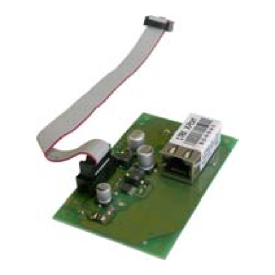
Fig. 1
Fig. 2 MP508TG
Fig. 3 MP508M/TG
Fig. 4
Fig. 5
ELKRON S.p.A.
Via Cimarosa, 39 – 10154 Torino (TO) - Italy
Tel. +39 (0)11.3986711 - Fax +39 (0)11.3986790
www.elkron.it – mail to:
info@elkron.it
ITALIANO
1
GENERALITÀ
L'interfaccia Ethernet permette di collegare la centrale
MP508TG o MP508M/TG (ver.2.00 o successive) a una
rete LAN (Local Area Network) oppure ad Internet tramite
un modem o un router ADSL.
È così possibile controllare e gestire l'impianto da remoto
tramite un PC dotato di Software "Hi-Connect" (fornibile
separatamente).
2
POSIZIONAMENTO
CENTRALE MP508TG
La scheda può essere inserita nell'armadio plastico
della centrale di fig.2 nelle posizioni A, B, C.
CENTRALE MP508M/TG
La scheda può essere inserita nell'armadio metallico
della centrale di fig.3 nelle posizioni A, B.
Nota: Se è montato il Modulo GSM IMG500 la
posizione consentita per MP508TG è solo C (fig.2) mentre
per MP508M/TG è solo A (fig.3).
3
MONTAGGIO SU CENTRALE MP508TG
• Togliere alimentazione alla Centrale.
• Posizionare
l'interfaccia
Ethernet
desiderata:
o PER ARMADIO PLASTICO: fissare con le viti in
dotazione in corrispondenza dei fori D (fig.1)
o PER ARMADIO METALLICO: fissare con le viti e
distanziali in dotazione in corrispondenza dei fori E
(fig.1)
• Inserire il cavo Flat 10 vie nel connettore polarizzato in
posizione A (fig.1)
• Inserire l'altra estremità del cavo Flat sull'apposito
connettore di centrale in posizione F (fig.4).
• Inserire il cavo Ethernet LAN sul connettore
indicato con B (fig.1)
• Alimentare la centrale.
Nota: Se presente, scollegare il cavo del PC
connesso a IT/USB-KEY, prima di alimentare la centrale.
4
FUNZIONAMENTO
L'interfaccia viene alimentata direttamente dalla centrale,
pertanto è necessario considerare anche il consumo max
dell' Interfaccia (110 mA) nel conteggio generale
dell'assorbimento dell'impianto.
All'accensione della centrale l'interfaccia effettua la ricerca
della Rete Ethernet. I LED posti sul connettore RJ45
lampeggiano per qualche secondo.
Se la Rete è presente il LED 1 (fig.5) rimane fisso e il
LED 2 (fig.5) lampeggia per indicare lo scambio dati.
Sulla scheda il LED C di fig.1 sarà acceso per indicare lo
stato di LINK.
Se la Rete non è presente o il cavo non è inserito
correttamente dopo l'inizializzazione il LED 2 (fig.5)
lampeggerà per qualche secondo con colore Ambra.
Nota: nonostante non ci siano vincoli riguardo alla
presenza simultanea sulla centrale MP508 delle Interfacce
IT Ethernet e IT USB/KEY, si ricorda che non è possibile
utilizzarle contemporaneamente per il trasferimento dati.
5
CONFIGURAZIONE DI DEFAULT
L'Interfaccia Ethernet è identificabile tramite il MAC
Address (Indirizzo ID) impresso sull'etichetta:
MAC
00-20-4A-XX-XX-XX
I parametri configurati in fabbrica sono i seguenti:
Parametro
Stato Default
Password
elkron1234
DHCP
No
IP
192.168.1.30
SMN
255.255.255.0
Gateway
192.168.1.1
Porta
8030
115200, 8, N, 1
Seriale
No ctrl flusso
Encryption
Disabilitata
(*) Per cambiare la programmazione fare riferimento alla
documentazione nel CD di installazione del software
"Hi-Connect" ver. 3.0 (cartella "Ethernet") utilizzando un
PC e il cavo Ethernet Cross a corredo.
6
CARATTERISTICHE TECNICHE
Tensione nominale di alimentazione: .................. 13,8 V—
(Da centrale su cavo flat)
Tensione di funzionamento min/max: .......... 9V— ÷ 15V—
Corrente nominale assorbita a 13,8 V:
Standby (Cavo Rete Eth.non connesso) ............ 60 mA
In funzione Rete Eth. 10Mbps (LED 1 Ambra).. 110 mA
In funzione Rete Eth. 100Mbps (LED 1 Verde)... 90 mA
Dimensioni (L x H x P), in mm........................ 86 x 54 x 18
7
OVERVIEW
The Ethernet interface is used to connect the MP508 TG
or MP508M/TG (version 2.00 or successive) control panel
to a LAN (Local Area Network) network or to the internet
through a modem or an ADSL router.
In this way, it is possible to control and manage the
remote plant through a PC with "Hi-Connect" Software
(supplied separately).
8
POSITIONING
MP508TG CONTROL PANEL
The card can be inserted in the control panel plastic
cabinet of fig.2 in the position A, B, C.
MP508M/TG CONTROL PANEL
The card can be inserted in the control panel metallic
cabinet of fig.3 in the position A, B.
Note: If the GSM IMG500 module is installed, the
allowed position for MP508TG is only C (fig.2) whereas for
MP508M/TG, it is only A (fig.3).
9
FITTING ON MP508TG CONTROL PANEL
• Remove the power supply from the control panel.
• Place the Ethernet Interface in the desired position:
nella
posizione
o FOR PLASTIC CABINET: fix it with the supplied
screws according to the holes D (fig.1)
o FOR METALLIC CABINET: fix it with the supplied
screws and spacers according to the holes E (fig.1)
• Insert the Flat 10 cable into the polarized connector in
position A (fig.1)
• Insert the other end of the Flat cable into the
appropriate control panel connector in position F (fig.4).
• Insert the Ethernet LAN cable into the RJ45 connector
shown in B (fig.1)
• Power the control panel.
RJ45
Note: If supplied, disconnect the cable from the PC
connected to the IT/USB-KEY, before powering the
control panel.
10
OPERATION
The interface is directly powered by the control panel;
therefore, the max. interface consumption (110 mA)
should also be considered when measuring the general
input of the system.
Upon control panel start-up, the interface searches the
Ethernet network. The LED on the RJ45 connector flashes
for a few seconds.
If the network is available, the LED 1 (fig.5) remains on
and the LED 2 (fig.5) flashes to indicate data exchange.
On the card, the LED C of fig. 1 will be on to indicate the
LINK status.
If the network is not available or the cable is not
correctly inserted after start-up, the LED 2 (fig.5) will flash
amber-coloured for a few seconds.
Note: although there are no restrictions to use the
IT Ethernet and the IT USB/KEY on the MP508 control
panel at the same time, please note that you cannot use
them together to transfer data.
11
DEFAULT CONFIGURATION
The Ethernet interface can be identified by MAC Address
(ID Address) printed on the label:
MAC
The default parameters are the following:
Program. (*)
Parameter
SI
Password
NO
DHCP
SI
IP
SI
SMN
SI
Gateway
SI
Port
NO
Serial
SI
Encryption
(*) To change programming, refer to the documentation on
the Software installation CD.
"Hi-Connect" version 3.0 ("Ethernet" page) using a PC and
the Ethernet Cross cable supplied.
12
TECHNICAL FEATURES
Rated supply voltage: ......................................... 13,8 V—
(from control panel to flat cable)
Min/max operating voltage: .........................9V— ÷ 15V—
Rated input current at 13.8 V:
Standby (Eth. network cable not connected)....... 60 mA
Eth. network on 10Mbps (LED 1 Amber)........... 110 mA
Eth. network on 100Mbps (LED 1 Green) ........... 90 mA
Dimensions (L x H x D), in mm.....................86 x 54 x 18
ENGLISH
00-20-4A-XX-XX-XX
Default state
Program. (*)
elkron1234
YES
No
NO
192.168.1.30
YES
255.255.255.0
YES
192.168.1.1
YES
8030
YES
115200, 8, N, 1
NO
No flow ctrl
Disabled
YES
Advertisement
Table of Contents

Related Manuals for Elkron IT Ethernet


Summary of Contents for Elkron IT Ethernet
- Page 1 MP508 delle Interfacce IT Ethernet and the IT USB/KEY on the MP508 control IT Ethernet e IT USB/KEY, si ricorda che non è possibile panel at the same time, please note that you cannot use utilizzarle contemporaneamente per il trasferimento dati.
- Page 2 Via Cimarosa, 39 – 10154 Torino (TO) - Italy (von der Zentrale über das Flachbandkabel) Tel. +39 (0)11.3986711 - Fax +39 (0)11.3986790 Min/Max Betriebsspannung: ....... 9V— ÷ 15V— www.elkron.it – mail to: info@elkron.it Leistungsaufnahme bei 13.8 V: Standby (Netzwerkkabel nicht verbunden) ..60 mA Eth.
Need help?
Do you have a question about the IT Ethernet and is the answer not in the manual?
Questions and answers