Table of Contents
Advertisement
Quick Links
Advertisement
Table of Contents

Related Manuals for Digilin LDMX-PWM-4


Summary of Contents for Digilin LDMX-PWM-4
- Page 1 4 Channel DMX LED Driver LDMX-PWM-4 User Manual © 2 0 1 6 D i g i l i n A u s t r a l i a . D o c u m e n t R e v : 5 . 2 - 4 N o v e m b e r 2 0 1 6...
-
Page 2: Table Of Contents
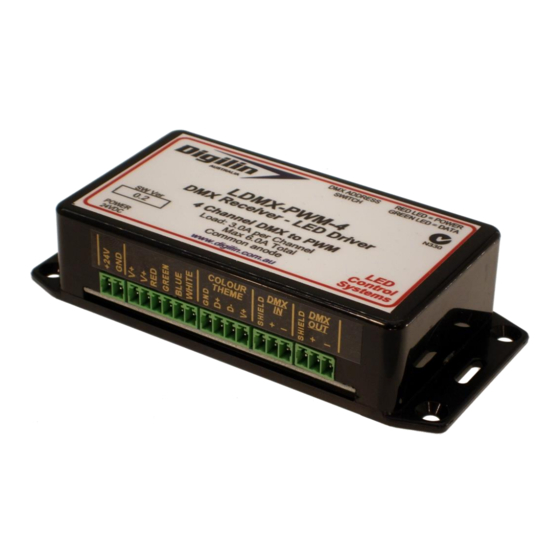
Figure 1 Front and rear view of the LDM-PWM-4. In addition to DMX input, the LDMX- PWM-4 also has a connector for direct interfacing to Digilin’s Colour Theme Controller, making a complete system simple to install and control. P a g e 2 o f 9... -
Page 3: Specifications
Operation Figure 2 Connection diagram. The LDMX-PWM-4 has a single 24VDC power supply. Once it is connected, the red power LED shown in Figure 2 will come on. If the unit is receiving good communications, the green DMX activity LED will also be on. -
Page 4: Using With Colour Theme Input
Fallback Output By default, the LDMX-PWM-4 outputs will be set at 50% for all channels at start-up and loss of DMX signal. P a g e 4 o f 9... -
Page 5: Appendix A. Dip Switch Settings
4 C h a n n e l D M X L E D D r iv e r - L D M X - P W M - 4 U s e r M a n u a l 5 .2 - 4 N o v e m b e r 2 0 1 6 Appendix A. - Page 6 4 C h a n n e l D M X L E D D r iv e r - L D M X - P W M - 4 U s e r M a n u a l 5 .2 - 4 N o v e m b e r 2 0 1 6 S w i t c h S w i t c h...
- Page 7 4 C h a n n e l D M X L E D D r iv e r - L D M X - P W M - 4 U s e r M a n u a l 5 .2 - 4 N o v e m b e r 2 0 1 6 S w i t c h S w i t c h...
- Page 8 4 C h a n n e l D M X L E D D r iv e r - L D M X - P W M - 4 U s e r M a n u a l 5 .2 - 4 N o v e m b e r 2 0 1 6 S w i t c h S w i t c h...
-
Page 9: Appendix B. Interconnection Detail Drawing
4 C h a n n e l D M X L E D D r iv e r - L D M X - P W M - 4 U s e r M a n u a l 5 .2 - 4 N o v e m b e r 2 0 1 6 Appendix B.
Need help?
Do you have a question about the LDMX-PWM-4 and is the answer not in the manual?
Questions and answers