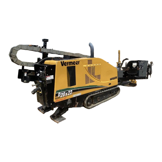
Vermeer Navigator D20x22 II Series Operator's Manual
Horizontal directional drill
Hide thumbs
Also See for Navigator D20x22 II Series:
- Operator's manual (260 pages) ,
- Maintenance manual (78 pages)

Related Manuals for Vermeer Navigator D20x22 II Series


Summary of Contents for Vermeer Navigator D20x22 II Series
- Page 1 D20x22 Series II Navigator ® Horizontal Directional Drill Operator’s Manual D20x22_Series_ii_o2_03 Serial No. 1001 - Order No. 105400CD3 Cabled Assembly No. 296338987...
- Page 2 This manual explains the proper operation of your machine. Study and understand these instructions thoroughly before operating or maintaining the machine. Failure to do so could result in personal injury or equipment damage. Consult your Vermeer dealer if you do not understand the instructions in this manual, or need additional information.
- Page 3 Right and left sides of the machine are determined by facing the power vises while seated at the controls. RADEMARKS VERMEER, VERMEER Logo, NAVIGATOR, ARMOR and QUICKFIRE are trademarks of Vermeer Manufacturing Company. DIGITRAK and AURORA are trademarks of Digital Controls, Inc.
- Page 4 Vermeer’s option without charge by any authorized independent Vermeer dealer. The warranty repair or replacement must be made by a Vermeer independent authorized dealer at the dealer’s location. Vermeer will pay for replacement parts and such authorized dealer’s labor in accordance with Vermeer’s labor reimbursement policy. Vermeer reserves the right to supply remanufactured replacement parts as it deems appropriate.
- Page 5 (7) Transportation costs, if any, of transporting to the Vermeer dealer. Freight costs, if any, of transporting replacement parts to the Vermeer dealer. (8) The travel time of the Vermeer dealer’s service personnel to make a repair on the retail purchaser’s site or other location (9) In no event shall Vermeer’s liability exceed the purchase price of the product, 10) Vermeer shall not be liable to any person under any circumstances for any incidental or consequential damages (including but not limited to, loss of profits, out of service time) occurring for any reason at any time.
- Page 6 (12) Depreciation damage caused by normal wear, lack of reasonable and proper maintenance, failure to follow operating instructions, misuse, lack of proper protection during storage. (13) Accessory systems and electronics not of Vermeer’s manufacture are warranted only to the extent of such manufacturer’s respective Limited Warranty if any.
- Page 7 NO DEALER WARRANTY. The selling dealer makes no warranty of its own and the dealer has no authority to make any representation or promise on behalf of Vermeer or to modify the terms or limitations of this warranty in any way.
- Page 8 Equipment Limited Warranty (the “Standard Limited Warranty”) for the Covered Components of the Specified Models of New Vermeer Industrial Equipment for the Lifetime of the Equipment provided that such Equipment is operated and maintained in accordance with the directions and instructions set forth in the Operator's and Maintenance Manuals. All conditions, exclusions and limitations of the Standard Limited Warranty apply.
-
Page 9: Engine
Receiving and Delivery Report EALER Check or perform the following: ___ Check for shipping damage or shortage. ___ Check that work area cones are supplied with the machine. ___ Check that certificates for electrically insulated gloves (1 pair) and boots (2 pairs) are supplied with the machine. ___ Check machine for loose bolts. -
Page 10: Hydraulics
___ Check coolant level and antifreeze concentration. ___ Check engine for correct operation. Hydraulics ___ Check hydraulic fluid level. ___ Check controls for correct operation. ___ Check all hydraulic components for leaks or damage. ___ Check vise cylinder pressure and operation of vises. ___ Check maximum thrust/pullback pressure. -
Page 11: Dealer/Owner Information
EALER WNER NFORMATION dealer owner address address city city state / province state / province zip / postal code zip / postal code country country phone number phone number email address email address D20x22 Series II Navigator HDD Receiving and Delivery Report iii... - Page 12 ACHINE DENTIFICATION UMBER ECORD Model Number Serial Number ACHINE DENTIFICATION ECAL This decal provides easy identification of the model and 17-digit identification number. The barcode contains the machine’s VIN number and can be scanned with any barcode reading device. iv Receiving and Delivery Report D20x22 Series II Navigator HDD...
-
Page 13: Engine Identification Number - Record
NGINE DENTIFICATION UMBER ECORD Engine Model Number Engine Serial Number D20x22 Series II Navigator HDD Receiving and Delivery Report v... - Page 14 This page intentionally left blank.
-
Page 15: Table Of Contents
Table of Contents Receiving and Delivery Report .....i Remote Lockout Indicators ......20-6 Dealer Prep . - Page 16 Manual Row Selector ......20-30 Remote Lockout System Intended Use ....30-1 Rod Joint Position Indicator .
- Page 17 Disconnect ....... . . 30-19 Drill Rods - Remove from Drill String ....30-41 Drill Tool Assemblies .
- Page 18 Adding Antifreeze to Drilling Fluid System ..30-63 Warning Cones ....... 40-18 Power Line Locator System .
- Page 19 Locating Equipment - Prepare ....50-13 Swivel Use ........50-28 Rod Wiper - Install .
- Page 20 PBD7500 Portable Breakout Device ....60-4 Intended Use ........60-4 Breakout Device Operation.
-
Page 21: Safety Messages
Section 10: Safety Messages General safety messages appear in this Safety Messages section. Specific safety messages are located in appropriate sections of the manual where a potential hazard may occur if the instructions or procedures are not followed. A signal word “DANGER”, “WARNING”, or “CAUTION” is used with the safety alert symbol. Safety signs with signal word “DANGER”, “WARNING”, or “CAUTION”... - Page 22 WARNING: Check machine before operating. Machine must be in good operating condition and all safety equipment installed and functioning properly. WARNING: Wear personal protective equipment. Dress properly. Refer to “Personal Protection,” page 40-6. WARNING: Keep spectators away. WARNING: Engine exhaust can asphyxiate. Operate only outdoors. 10-2 Safety Messages D20x22 Series II Navigator HDD...
- Page 23 WARNING: Use Shutdown Procedure before servicing, cleaning, repairing or transporting machine. Refer to page 50-3. WARNING: Pressurized fluid can penetrate body tissue and result in serious injury or death. Leaks can be invisible. Keep away from any suspected leak. Relieve pressure in the hydraulic system before searching for leaks, disconnecting hoses, or performing any other work on the system.
-
Page 24: Fire Extinguisher
WARNING: Hot fluid under pressure can scald. Allow engine to cool before opening radiator cap. WARNING: Failure to follow any of the preceding safety instructions or those that follow within this manual, could result in serious injury or death. This machine is to be used only for those purposes for which it was intended as explained in this Operator’s Manual. -
Page 25: Welding Precautions
Section 11: Welding Precautions ELDING LERT LECTRONIC OMPONENTS NOTICE: Electronic modules and controllers will be damaged from stray voltages and currents generated during welding if not unplugged before welding. To prevent extensive and costly damage to the electrical components: Turn Battery Disconnect Switch (1) to DISCONNECT. Step 1: NOTICE: Disconnecting the battery ground with the battery disconnect switch will not prevent damage to the electronic... - Page 26 Unplug Tethered Transport Control (6). Step 4: Tier 4 Interim/Stage IIIB engine: unplug engine ECU (7), located on left Step 5: side of engine. Connect welding ground as close to work as possible. Step 6: 11-2 Welding Precautions D20x22 Series II Navigator HDD...
-
Page 27: Intended Use
Section 15: Intended Use The Vermeer D20x22 Series II Navigator Horizontal Directional Drill is designed solely for use in creating horizontal bores through the earth. Utilities are typically installed in these underground bores during pullback. Always use the machines in accordance with the instructions contained in this Operator’s Manual, safety signs on the machine, and other material provided by Vermeer Corporation. - Page 28 This page intentionally left blank.
-
Page 29: Machine Controls
Section 20: Machine Controls TRIKE LERT ONTROLS Alarm Cancel Key Press after Strike Alert alarm sounds and the cause has been corrected. Test Key Press to test voltage and current sensing circuits. Alarm on drill unit must sound. Test Strike Alert system with the voltage stake fully inserted into the ground. Do not test with stake in its storage cradle, lying on the machine, or lying on the ground. -
Page 30: Remote Lockout Controls
Remote Lockout Controls EMOTE RANSMITTER ONTROLS In order for the remote transmitter to function, machine ignition key must be ON and operator must be seated. (1) Power ON/OFF Button (black) Press and hold until yellow light flashes....... ON Press and hold until all lights are off . -
Page 31: Indicator Lights
Indicator Lights Flashing or steady lights indicate various operating conditions. LOCKOUT Mode Light Red steady... . . drill rotation, thrust/pullback, and fluid locked out RUN Mode Light Green steady ......drill control returned to operator Green flashing . -
Page 32: Remote Lockout Machine Controls
EMOTE OCKOUT ACHINE ONTROLS (1) Alarm Cancel Key Press to cancel continuously sounding alarm (2) when radio communication is not established. (2) Alarm Alarm sounds with a series of beeps or continuous tone to indicate various operating and Remote Lockout system conditions. Indicator Lights Flashing or steady lights indicate various operating conditions. -
Page 33: Remote Lockout Battery Charger
EMOTE OCKOUT ATTERY HARGER Battery Charger Located inside compartment to the left of the seat. Insert battery into charger. Amber light flashes when battery is fully charged. Green light indicates charger is receiving power. Transmitter Storage Located inside compartment in right hand control console. D20x22 Series II Navigator HDD Machine Controls 20-5... -
Page 34: Remote Lockout Indicators
EMOTE OCKOUT NDICATORS TRANSMITTER INDICATORS INDICATION FUNCTION/STATUS Green RUN Light Steady RUN mode. Machine not locked out. Flashing Lockout requested; waiting for confirmation. Red LOCKOUT Light Steady LOCKOUT mode. Machine is locked out. Yellow Light Flashing No radio communication between transmitter and machine. Double flashing Remote is in Registration mode. -
Page 35: Engine Controls
Engine Controls ATTERY ROUND ISCONNECT Battery Disconnect Switch Rotate key counterclockwise ... . . disconnect ground Rotate key clockwise..... . connect ground YDRAULIC NABLE UTTON... -
Page 36: Engine Controls - Drill Station
NGINE ONTROLS RILL TATION (1) Keyswitch ..........1st position counterclockwise . -
Page 37: Emergency Shutoff Switch
MERGENCY HUTOFF WITCH (1) Emergency Shutoff Switch, Transport Station Push........to shut off engine Pull out . - Page 38 Rotation Handle (2) Throttle Up Button Press....... . . increase engine RPM (3) Throttle Down Button Press.
-
Page 39: Engine Monitors
NGINE ONITORS (1) High Coolant Temperature Light (red) Comes on if coolant becomes too hot (2) Low Oil Pressure Light (red) Comes on when oil pressure is low (3) Insufficient Voltage Light (yellow) Comes on when voltage not sufficient (4) Warning Light (yellow) Comes on when engine shuts down due to low engine oil pressure or high coolant temperature (5) Display... -
Page 40: Transport Station Controls
RANSPORT TATION ONTROLS Ground Drive Range Switch Press top ..........high Press bottom . - Page 41 Left Rear Stabilizer Lever Right Rear Stabilizer Lever Push ........lower stabilizer Pull .
-
Page 42: Tethered Transport Control (Option)
ETHERED RANSPORT ONTROL PTION (1) Engine Stop Switch Press........shut off engine (2) Transport Joystick Multi-directional: push in the direction you wish to drive. - Page 43 Throttle Push up......... . increase Push down .
-
Page 44: Setup Controls
Setup Controls TAKEDOWN ONTROLS Stakedown Control Selector Push top ......select right stakedown Push bottom . -
Page 45: 40˝ Stakedowns (Option)
40˝ Stakedowns (Option) Transport Position Drilling Position Turn pin (3) to fit through slot to remove. Install in desired position and turn to secure. D20x22 Series II Navigator HDD Machine Controls 20-17... -
Page 46: Thrust/Pullback Controls
HRUST ULLBACK ONTROLS Thrust/Pullback Handle (Right Handle) Pull ....... . . pull back (retract) drill Push . -
Page 47: Rotation Control
OTATION ONTROL Drill Rotation Handle (Left Handle) Pull ........rotate clockwise Use for drilling forward or backreaming. -
Page 48: Autodrill Controls
RILL ONTROLS AutoDrill Button Press and release ....activate AutoDrill mode AUTO Move either Rotation or Thrust/Pullback Handle to pause AutoDrill mode. AutoDrill Resume Button Hold for 1.5 seconds to resume AutoDrill after pausing. - Page 49 AutoDrill Selector Switch Toggle ..... Constant Thrust/Pullback Speed ....... . SPEED shown on display Toggle second time .
-
Page 50: Controls
R.A.T.T. C ONTROLS (1) Manual Pressure Limit Key Activates and toggles between Thrust/Pullback Pressure limit, Rotation Pressure limit, and no pressure limits. Use Trim Switch (page 20-21) to adjust limits. (2) R.A.T.T. Mode Key Activates R.A.T.T. Oscillation mode and then toggles between Oscillation mode and Straight Drilling mode (3) R.A.T.T. -
Page 51: Drill Station Controls
Drill Station Controls PERATOR RESENCE ONTROLS Operator Presence Switch The machine is equipped with an Operator Presence system in the seat. The operator must be sitting in the seat for drill rotation, drill thrust, and rod loader to function. This system is intended for your safety and must be maintained in good functional condition. -
Page 52: Fuses
USES Fuses protect electrical circuits and are located in compartment under left armrest. When replacing them, use fuses with the correct rating to prevent damaging electrical system. Tier 3/Stage IIIA Engine Tier 4 Interim/Stage IIIB Engine Lights Lights F1-15A F1-15A Front Throttle Up Stakedown... -
Page 53: Auxiliary Outlet
UXILIARY UTLET (1) 12-Volt Auxiliary Outlet Use outlet to operate 12-volt 150-watt electrical accessories. A 15- amp breaker protects the circuit. IGHTS (1) Switch Press top ........lights on Press bottom . -
Page 54: Power Vise Controls
OWER ONTROLS Front Vise Switch Push up ....... . clamp front drill rod Push down. -
Page 55: Rod Loader Controls
OADER ONTROLS Rod Transfer Arms Retract Button (right joystick) Press trigger up ......... . . - Page 56 Rod Transfer Arm Barrier The barriers automatically move out with the first movement of the rod loaders arms. Fold barriers back in manually before transporting. 20-28 Machine Controls D20x22 Series II Navigator HDD...
-
Page 57: Rod Loader Row Selector
OADER ELECTOR (1) Position 1 ......loader under first row (2) Position 2 ......loader under second row (3) Position 3 . -
Page 58: Manual Row Selector
Manual Row Selector If cable (1) from Row Selector Lever (refer to previous page) is frozen or stuck: Remove pin (2) to Step 1: disconnect cable. Remove pin (3) and move Step 2: bracket (4) up or down to desired position. Refer to decal on bracket. -
Page 59: Rod Joint Position Indicator
OINT OSITION NDICATOR Position 1 ..........When marker (1) is at left decal (2), rod joint is positioned between rear and front vises. -
Page 60: Drilling Fluid Controls
RILLING LUID ONTROLS (1) Fluid System ON/OFF Switch Push up ..... . fluid system ON (variable flow) Push down ....... . fluid system OFF (2) Fluid Full Flow Button Press and hold . - Page 61 Wash Wand Quick Coupler Fluid Tank System Valve Rotate down (handle 90º to valve body) ....flow OFF Rotate up (handle in-line with valve body) ... . . flow ON Antifreeze Supply Valve Rotate handle in-line to valve body .
-
Page 62: Engine Access
NGINE CCESS Hood Latch To open hood, turn latch and pull up on front of hood. Hood Release Lever To close hood, push lever down to release latch, then close hood. 20-34 Machine Controls D20x22 Series II Navigator HDD... -
Page 63: Electronic Controller
Section 21: Electronic Controller This section shows locations and identification of control keys and indicator lights on the electronic controller, as well as symbols used on the display screen. Refer to for information on controls and lights Machine Controls within each function. Refer to page 20-1. - Page 64 Remote Lockout Alarm Cancel Key Press to cancel continuously sounding alarm when radio communication is not established. Service Screen Key Refer to “Service,” page 21-13. Increase/Decrease Keys Use these switches to increase or decrease the – degrees of oscillation, or use with Service Screen Key to move through Service Menu.
-
Page 65: Controller Lights
ONTROLLER IGHTS Low Engine Coolant Temperature Light (red) Comes on if coolant becomes too hot Strike Alert Light (green) ON: Strike Alert system test passed FLASHING: Sensor failure, voltage stake not in ground, or voltage stake wiring problem OFF: Bulb burned out or problem in wire harness R.A.T.T. - Page 66 Low Battery Voltage Light (yellow) Comes on when voltage not sufficient Anti-Crash Light (red) Comes on when rod loader arms are extended Warning Light (yellow) Comes on when engine shuts down due to low engine oil pressure or high coolant temperature (10) AutoDrill Light (green) Solid.
-
Page 67: Screen Symbols
CREEN YMBOLS Rotation active Thrust/Pullback active Drilling Fluid Pump ON Drilling Fluid Pump Flow in GPM R.A.T.T. Mode Active Indicator R.A.T.T. Mode Oscillation Angle in degrees Adjust with Increase/Decrease Keys R.A.T.T. Thrust Pressure Limiting Enabled Drill Carriage Position Indicator (9) Carriage between slowdown switch position and carriage stop switch position . - Page 68 High Speed Rotation (11) High Speed Thrust (12) Wash Wand Available; flow in GPM (13) Maximum flow is 5 gpm Bar Graph - indicates amount of rotation output (14) Bar Graph - indicates amount of thrust output (15) Save Pressure Limit Setting (16) Appears when Enter Key is pressed to save settings.
- Page 69 AutoDrill Mode Select (22) Constant Thrust/Pullback Pressure Mode Active Constant Rotation Pressure Mode Active Constant Thrust/Pullback Speed Mode Active Thrust/Pullback Output (23) Use Speed/Pressure Trim Switch to increase or decrease value. Thrust/Pullback Pressure changing, (24) which decreases thrust speed output Rotation Pressure changing, (25) which decreases thrust speed output...
-
Page 70: Startup Screen
TARTUP CREEN Model Selection: One of three screens will be displayed at startup. If your machine model is not displayed (1) at the bottom, use the Increase or Decrease Key to choose another model. Then press Enter Key. Other messages that are displayed at bottom of screen: Waiting for Key . -
Page 71: Information Screens
NFORMATION CREENS Press Menu Key to access Options Menu. Press plus or minus keys to scroll through the next three screens. Refer to the following pages for more information on each screen. Options Menu Information Menu Read information on software revisions of Remote Lockout, Strike Alert, DP10, or controller. Fault Log View fault codes and clear. -
Page 72: Options Menu
Options Menu • To scroll through screens in left column, use Increase or Decrease Key. • To modify options, use Enter Key. ROTPSI....current rotation pressure ..PSI or bar, depending on UNITS chosen THRPSI. -
Page 73: Information Menu
Information Menu • To scroll through screens in left column, press Increase or Decrease Key. • To display complete information, press Enter Key. • All screens display software part number and revision Controller Remote Lockout Also displays whether hydraulic or engine shutdown mode has been selected. -
Page 74: Fault Log
Fault Log Press Enter Key to select fault code. Press Increase or Decrease Key to scroll or to Clear. Fault code is displayed. Press Enter Key to clear log of all fault codes. 21-12 Electronic Controller D20x22 Series II Navigator HDD... -
Page 75: Service
ERVICE Engine shuts down when light (1) is solid. Press Service Screen Key (2) to view message from table below on display (3). Contact your Vermeer dealer for solutions. Operator Warnings and Fault Messages Rotation transducer voltage low Rod loader retract fault (green-4) - Page 76 Excess diesel particulate level; unable to regenerate; Track enable fault (black-6) service DPF now Rear (upper) vise close fault (brown-2) DPF regen inhibited due to throttle Front (lower) vise open fault (green-3) DPF regen inhibited due to out of neutral Front (lower) vise close fault (green-2) DPF regen inhibited due to park brake off Rear (upper) vise rotate fault (brown-3)
-
Page 77: Overrides Menu
Overrides Menu To scroll through screens in left Step 1: column, use Increase or Decrease Keys. To modify options, use Enter Key. Step 2: Press Increase or Decrease Keys to Step 3: manually activate or deactivate each control. NOTICE: Engine must be shut off for this procedure. -
Page 78: Dpf Menu (Tier 4 Interim/Stage Iiib Engine Only)
DPF Menu (Tier 4 Interim/Stage IIIB Engine Only) DPF Menu Key Press to access DPF menu. Diesel Particulate Filter Symbol Appears when a forced regeneration is required. If regeneration is inhibited, the symbol will flash. DPF Regeneration Inhibited Symbol Indicates regeneration has been disabled manually. High Exhaust System Temperature (HEST) Symbol Indicates exhaust gas temperature is high, idle is elevated, and automatic regeneration is in process. -
Page 79: Dpf Regen Display Status
DPF Regen Display Status • OFF: When OFF, passive regeneration is underway. • AUTO: Automatic regeneration is underway. • PARKED MODE: Machine functions are locked out, preparation for a forced regeneration. Passive Regeneration The DPF is self-cleaning and generally requires no operator action. Passive regeneration means the engine is operating at a high enough temperature (more than 570°F/300°C) to burn particulate as it is created, and none is being emitted. -
Page 80: Forced (Manual) Regeneration
Forced (Manual) Regeneration A forced regeneration is required if: • The fault message at right appears, or • The Diesel Particulate Filter Symbol (1) appears, or Coolant temperature (2) reads • 150°F (65°C) or higher. Refer to the next page for forced regeneration procedure. - Page 81 Park machine in a location so exhaust is not directed at any Step 1: surface or material that may become hazardous. Press DPF Menu Key (3). Step 2: Select “Parked Mode” (4), and use Enter Key (5) to turn it ON to Step 3: disable tracking and drilling functions.
- Page 82 Contact your Vermeer dealer if either of these two fault messages appears: • Excess Diesel Particulate Lvl, Park Regen by Service Tool Req •...
- Page 83 Section 22: DigiTrak Aurora Display The DigiTrak Aurora display accepts telemetry signals from all DigiTrak receivers except the LT. Refer to the Aurora Operator’s Manual and Quick Start Guide included with the machine’s Reference Library or at www.DigiTrak.com, under Support & Support > Downloads. For more information: •...
- Page 84 This page intentionally left blank.
-
Page 85: Overview
Section 30: Overview Remote Lockout Overview The Remote Lockout system is not intended to replace good verbal radio communication. Radio communication is essential to the Remote Lockout system process. Refer to “Radio Communication Requirements,” page 40-3. EMOTE OCKOUT YSTEM NTENDED The Remote Lockout system is a communication and control tool that allows a worker anywhere along the bore path or at the exit site, to directly lock out drill rod rotation, thrust, and fluid flow. -
Page 86: Remote Lockout System Component Identification
NOTICE: Do not rely on the Remote Lockout system as an emergency stop. It is very unlikely that disabling thrust and rotation could be done quickly enough to prevent death or serious injury. The Remote Lockout system will not shut down the power units on stand-alone drilling fluid systems or air compressors. -
Page 87: Remote Transmitter
EMOTE RANSMITTER The remote transmitter (1) clips onto the user’s belt and has a range of 3300 ft (1 km). The range is dependent on usage in urban or rural areas, and on weather and environmental conditions. The remote transmitter user can select either RUN or LOCKOUT mode, indicated by lights and buzzer. -
Page 88: Power On/Off Button
Power ON/OFF Button The Remote Lockout system can be turned on by pressing Power ON/OFF Button (1) and holding for 2 seconds, or by pressing Lockout Button (2). Press Power ON/OFF Button (1) and hold for 2 seconds to shut off transmitter power. When the remote transmitter power is on, at least one light should be illuminated. -
Page 89: Lockout Button
Lockout Button With the remote lockout transmitter power turned on, pressing and releasing the red Lockout Button (2) sends a lockout command to stop drill string rotation, thrust and pullback, and fluid flow. When remote transmitter is OFF, pressing and holding Lockout Button until the yellow light begins flashing will turn on the remote transmitter and then send a lockout command. -
Page 90: Remote Lockout Tests
Test lockout of thrust and rotation by moving Thrust and Rotation Levers out of NEUTRAL. Thrust Step 6: and Rotation must not function. If Thrust or Rotation moves, contact your Vermeer dealer. After successful Lockout test, press and hold the green button (3) for 2 seconds to return to Drill mode. -
Page 91: Engine Shutdown Test
Machine is now in Lockout mode. Engine must shut down. If engine does not shut down, contact your Vermeer dealer immediately. After successful Lockout test, press and hold the green button (3) for 2 seconds to return to Drill mode. -
Page 92: Hydraulic Lockout Or Engine Shutdown Option
YDRAULIC OCKOUT OR NGINE HUTDOWN PTION The Remote Lockout system is equipped with an option to operate as either a hydraulic lockout (default) or an engine shutdown system. Plugs and connectors are located in the compartment below left control console. To change the system to engine shutdown: Move ignition key to OFF position. -
Page 93: Hydraulic Lockout Backup Engine Shutdown
Hydraulic Lockout Backup Engine Shutdown To ensure drill remains locked out during a confirmed hydraulic lockout, rotation water pump flow, and thrust hydraulic pressures and the control circuit for drilling fluid are monitored. If any of the hydraulic pressures increase, or if drilling fluid system is turned on, engine will be shut down. The engine cannot be started in Drill mode until Run Button on the remote transmitter is pushed and Run mode is confirmed. -
Page 94: Remote Lockout Indicators
EMOTE OCKOUT NDICATORS A table illustrating all Remote Lockout system indicators is in the section. Refer to “Remote Machine Controls Lockout Indicators,” page 20-6. Fault Check/Processing Lights When green and/or yellow lights are flashing without the buzzers sounding, the system is processing a transition from one mode to another. -
Page 95: Remote Registration
EMOTE EGISTRATION If the Remote Lockout system base or transmitter are replaced, registration of the two components must take place. Turn Ignition Switch to ON. Step 1: Open compartment below left Step 2: console. Remove 2-pin jumper (1) Step 3: used to select Hydraulic Lockout or Engine Lockout mode. -
Page 96: Battery Condition
Amber light on side of charger will flash when battery is charging, and will be on solid when fully charged. Green light in same location will come on to indicate power to the charger. Additional chargers may be purchased from your Vermeer dealer for charging the battery in an auxiliary vehicle. -
Page 97: Remote Lockout System - Start
EMOTE OCKOUT YSTEM TART Remove battery from charger and install in remote transmitter. Step 1: Sit in the operator’s seat and turn ignition key to RUN position. Step 2: Turn remote transmitter on by pressing Power ON/OFF Button and holding for 2 seconds. Step 3: Press and hold Run Button for 2 seconds to select Run mode. -
Page 98: Lockout Procedure - With Remote Lockout
OCKOUT ROCEDURE EMOTE OCKOUT DANGER: Rotating drill string can kill. Unexpected startup possible. Lock out before working on drill string. It is essential that the machine is locked out before entering an exit pit, changing tools, repairing drill rod, manually adding or removing drill rod, or performing any other work on the drill string or tools. The Remote Lockout system will not shut down the power units on stand-alone drilling fluid systems or air compressors. - Page 99 Anytime a remote lockout command is not successful, ensure machine is running, is in Drill mode (operator seated at controls), and that transmitter is within range. If problem still exists, contact your Vermeer dealer to determine the source of the problem. •...
-
Page 100: Resuming Operation After Remote Lockout
Resuming Operation after Remote Lockout Verify that drill rod and cutting tools are ready for operation. Step 1: Warn everyone who may be exposed to drill string or cutting tools that operation Step 2: will resume. Confirm everyone has evacuated the exit pit and is away from drill string and Step 3: cutting tools, and that no wrenches or breakout tools are attached to drill string or cutting tools. -
Page 101: Lockout Procedure - Without Remote Lockout System
OCKOUT ROCEDURE ITHOUT EMOTE OCKOUT YSTEM DANGER: Rotating drill string can kill. Unexpected startup possible. Lock out before working on drill string. It is essential that the machine is locked out before entering an exit pit, changing tools, repairing drill rod, manually adding or removing drill rod, or performing any other work on the drill string or tools. -
Page 102: Drill Rod And Tools
Use only drill rods, drilling tools, and breakout device described in this manual or approved by Vermeer Corporation. • Before using a new drill rod, tap drill rod against a hard surface, such as a wood block, to dislodge scale and rust inside. -
Page 103: Drill Tool Connections
RILL ONNECTIONS Drill tools that must be removed to attach a backreamer to the drill string must have a manually threaded joint with collar. Such tools are not torqued and do not require breakout tools to uncouple the joint. Threaded Connections - Hex and Quickfire Connect Clean all connecting surfaces. -
Page 104: Drill Tool Assemblies
RILL SSEMBLIES Refer to Fundamentals of Horizontal Directional manual for tool selection guidelines. Drilling Drilling Head Assembly Choose a bill (1) to match soil Step 1: conditions, desired hole size, and type of service. Attach bill to drill head (2) using Step 2: mounting bolts (3). - Page 105 Install drill head cover (6) and Step 6: secure with retaining pins (7) and roll pins (8). D20x22 Series II Navigator HDD Overview 30-21...
-
Page 106: Armor Drill Housing Assembly
RMOR RILL OUSING SSEMBLY Attach housing (1) to drill string starter rod. Refer to Step 1: “Threaded Connections - Hex and Quickfire,” page 30-19. Follow instructions of transmitter for battery installation Step 2: and check function of transmitter. A variety of transmitters are available that will fit inside drill head cavity. - Page 107 Attach cover (5) with roll pin (6). Step 6: Install one socket head cap screw (7). Install O-rings (8), then bit (9) onto Step 7: housing. Insert solid cross pin (10) chamfer first. Hammer only on the rounded side of the pin. Install other socket head cap screw Step 8: (7).
-
Page 108: Armor Multi-Tool
Armor Multi-Tool Remove end cap (1) from handle of multi-tool and remove components. • Screwdriver (2) - Used to scrape debris from holes in housing and bit. • Hex Shaft (3) - Used to install and remove socket head cap screw that secures lid and bit cross pin. -
Page 109: Rotary Tooth Installation/Extraction - Gauntlet Bit
Rotary Tooth Installation/Extraction - Gauntlet Bit Installation Align tooth shaft with mounting hole on bit. Place countersunk hole (6) over tooth. Hammer on back side of multi-tool, seating tooth fully. Extraction Using the 3/8" drive pin (5), push teeth out from the bit, fully exposing groove on tooth. -
Page 110: Pvc Pipe Pulling (Option)
PVC P ULLING PTION The PVC puller assembly is used to pull PVC pipe back through the bored hole. Three different sizes of PVC pipe can be pulled by using the respective size pulling kits for 2˝, 3˝, or 4˝ PVC pipe. Assemble pipe lengths (if more than one) with the PVC puller (1). -
Page 111: Reamer Installation
Reamer Carrier - Intended Use Vermeer reamer carriers are used to lift heavier reamers weighing more than 50 lb (23 kg). The carrier provides an easy method of installing or removing reamers at the exit site while the machine is locked out. While holding the reamer with the carrier, the reamer can be turned by hand without rotating the drill string. -
Page 112: Reamer Carrier Components
Reamer Carrier Components The reamer carrier has a sliding frame (1) for adjustment to fit various size reamers and drill tools. Remove hairpin and pin (2) to adjust slide. The pin end (3) of reamer carrier, located at bottom of sliding frame, connects to the reamer. -
Page 113: Reamer Carrier - Install/Remove
Reamer Carrier - Install/Remove Using the reamer carrier requires a minimum of two persons, one to attach and guide reamer carrier, and one to operate the lifting device. It is recommended that two persons work together to install the reamer carrier onto the reamer. To install reamer carrier: Remove hairpin (1) and pin. -
Page 114: Turnbuckle - Adjust
Turnbuckle - Adjust A turnbuckle (1) may be used for angular adjustment of reamer to drill string. Use appropriate-sized chain and turnbuckle for reamer and reamer carrier weight. WARNING: Do not lift a reamer that exceeds the weight limit of the carrier. -
Page 115: Reamer - Connect With Threaded Connection
Reamer - Connect with Threaded Connection Ensure drilling machine has been locked out. Step 1: Ensure components are clean. Step 2: Lubricate threaded end of reamer. Step 3: Align reamer with drill string and manually turn reamer by hand until reamer is completely threaded Step 4: onto drill string. -
Page 116: Reamer - Connect With Hex Collar Connection
Reamer - Connect with Hex Collar Connection Ensure drilling machine has been Step 1: locked out. Ensure components are clean. Step 2: Lubricate threaded end of reamer. Step 3: When aligned with rod, manually Step 4: rotate reamer to begin threading reamer into rod. -
Page 117: Rod Loader
Rod Loader WARNING: Falling load can crush. Never lift rod box over people. Do not stand or work under raised rod box. WARNING: Pinch points can result in serious crushing injuries. Keep hands and feet away from pinch points of rod loader. Keep shields in place and correctly secured. Always store drill rods in the rod box to prevent contact with the ground. -
Page 118: Rod Box
Rod Box - Load Remove two top rod box pins (1) from Step 1: top of rod box. Unlatch and swing up bar (2) in Step 2: middle of box. Load rods into rod box. Step 3: Replace top pins and bar. Step 4: Rod Box - Install Connect hoist chain to all four lift eyes (3). -
Page 119: Rod Box - Remove
Rod Box - Remove If rod box is not empty, raise rod box Step 1: cylinders to push rods into rod box. Shut off engine. Step 2: Install bottom rod box support bars Step 3: (6) and retainer pins (5). Lower rod box cylinders and shut off engine. -
Page 120: Rod Joints
OINTS Rod Joints - Tighten Refer to Drill Rotation Pressure/Torque Gauge (1) when tightening rod joints to check rotation torque pressure. Tighten rod joints to 2000–2300 psi (138–159 bar). Rod Joint Position Indicator • When marker (1) is positioned at left side of decal (2), rod joint is positioned between rear and front vises. -
Page 121: Drilling
RILLING Drill Rods - Add to Drill String To add first rod from rod box to starter rod: Set Row Selector Lever (1) to unload from Step 1: first row (row closest to operator). Rows must be emptied sequentially, from first row through the fifth row, to prevent rods from being dumped out of the rod box. - Page 122 Press Rod Lower Switch (4) to lower rod lifter to Step 4: (Step 4) load a rod onto transfer arm. Press Rod Transfer Extend Button (5) to move Step 5: rod transfer arm to drill string. Rod lift and lower functions do not operate when the front vise is open.
- Page 123 When rod begins to rotate, move rod transfer Step 9: (Step 9) arm (8) back under rod box. NOTICE: Failure to fully move rod transfer arm back under rod box will damage rod transfer arm. With minimum thrust, full rotation, and with Step 10: front vise clamped on downhole rod, thread upper rod into downhole rod and tighten to...
-
Page 124: Greaser (Option)
Greaser (Option) The machine may be equipped with a greaser bucket (1) for lubricating drill rod threads. Press Grease Button (2) on left joystick to release grease. To adjust, remove plug (3) at top of tube with Allen wrench, and rotate threaded screw inside IN to increase grease amount, or OUT to decrease grease amount. -
Page 125: Drill Rods - Remove From Drill String
Drill Rods - Remove from Drill String To remove rod from drill string and load into rod box: Move Row Selector Lever (1) to load into row farthest from operator that is Step 1: not full of rods. As each row is filled, move Row Selector Lever to the next lower numbered row. - Page 126 Push up Front Vise Switch (4) to clamp onto (Step 8) Step 4: downhole rod. Push up Rear Vise Switch (5) to clamp and rotate Step 5: upper drill rod to break front joint. Press Vise Rotation Button (6) to rotate rear vise Step 6: to break joint.
- Page 127 Using only rotation, unthread joint until rod joint position marker (2) Step 9: stops moving rearwards. While continuing to rotate in reverse, pull rod back until marker (2) is at right hand decal (3). Stop rotation and pullback. Step 10: Engage rear vise by pushing up on Rear Vise Switch (5).
- Page 128 Press Rod Transfer Arm Retract Button (9) to Step 15: move rod transfer arm (7) away from drill string to position rod (8) under rod box column to be loaded. Press Rod Lifter Button (10) to raise rod Step 16: lifter (11) and lift rod into rod box.
-
Page 129: Row Selector Lever - Pulling Back
Row Selector Lever - Pulling Back Move Row Selector Lever (1) when row has been completely filled. Extend rod transfer arm. Step 1: Move lever to next row. Step 2: D20x22 Series II Navigator HDD Overview 30-45... -
Page 130: Power Vise Operating Guidelines
OWER PERATING UIDELINES • Inspect vise jaws and grips and replace worn or damaged components before drilling. • Stake drill unit down securely. If rack shifts during drilling, the rod will become misaligned between the jaws. Check alignment to prevent jaw or rod damage. •... -
Page 131: Drilling Modes Overview
Drilling Modes Overview ANUAL In the default Manual mode, thrust and rotation pressures are determined by the drilling conditions and are limited by the system pressure (3000 psi/207 bar). No display lights are ON. R.A.T.T. M To switch from Normal Drill mode to R.A.T.T. mode, press R.A.T.T. Mode Key (1) once to activate Oscillation mode. -
Page 132: Disabling R.a.t.t. Drilling Mode When Oscillation Mode Is Active
Disabling R.A.T.T. Drilling Mode When Oscillation Mode Is Active If R.A.T.T. Oscillation mode is active (lights 3, 4 & 5 ON), the following sequence must be followed to disable it: Press (1) once to go from Oscillation to Straight Drilling mode. Light (3) Step 1: will turn OFF. -
Page 133: Default R.a.t.t. Drilling Pressure Limits
Default R.A.T.T. Drilling Pressure Limits The factory-set default setting is RATOFF when the engine is started. To activate R.A.T.T. rotation and pressure limits on engine startup, use the following procedure: Press Service Screen Key (1). Step 1: Press and hold R.A.T.T. Mode Key (2). Step 2: While holding R.A.T.T. -
Page 134: Rod Wrap And R.a.t.t. Oscillation
Rod Wrap and R.A.T.T. Oscillation As drilling distance increases, drill string windup increases with the longer drill string. The result is rod wrap and the drill head rotates fewer degrees than the drive chuck. To maintain the drill head rotation angle when steering with a long drill string, the drive chuck rotation angle must be increased to compensate for rod wrap. -
Page 135: Setting Manual Pressure Limits
Setting Manual Pressure Limits Manual Limit Key Rotation Limiter Light Thrust Limiter Light Press (1) once ....enable both Thrust/Pullback and Rotation limits; ......Rotation (2) and Thrust/Pullback (3) lights are ON Press (1) a second time . -
Page 136: Setting Manual Thrust Limits
Setting Manual Thrust Limits Select drilling mode to be adjusted. Step 1: Press Manual Pressure Limit Key (1). Step 2: Turn R.A.T.T. ON or OFF as needed. Step 3: Place AutoDrill Selector Switch (4) to the THRUST position. Step 4: Adjust the thrust pressure limit with the Speed/Pressure Trim Switch (5). -
Page 137: Autodrill
RILL In AutoDrill mode, the operator can release the Thrust/Pullback and Rotation Handles and the drill will continue to operate. The AutoDrill may be used in all drilling modes and in combination with both R.A.T.T. modes (Oscillation and Straight Drilling). The operator can set one of three constant control operating modes: •... -
Page 138: How Autodrill Works
RILL ORKS In all three modes, the AutoDrill program maintains the constant speed or pressure by limiting the thrust pump output. The AutoDrill program monitors both the rotation and thrust/pullback pressures for: • how rapidly the pressures are rising • the duration of the pressure increase •... -
Page 139: When Limits Are Exceeded
When Limits are Exceeded If these values exceed their limits, a message will be displayed: • In Thrust Pressure mode: ROTPSI • In Rotation Pressure mode: THRPSI • In Speed mode: THRPSI or ROTPSI, whichever pressure limit has been exceeded The messages mean the thrust pump output is reduced until drilling conditions come back within limits: •... -
Page 140: Autodrill - Enable (Normal Drilling)
RILL NABLE ORMAL RILLING Select AutoDrill mode (Constant Thrust/Pullback Speed, Constant Thrust/ Step 1: Pullback Pressure, or Constant Rotation Pressure) using AutoDrill Selector Switch (2). Move and hold Rotation and Thrust/Pullback Handles to obtain the desired Step 2: rotation and thrust/pullback motion for the current drilling conditions. Momentarily press and release AutoDrill Button (1) and immediately release the Step 3: Rotation and Thrust/Pullback Handles. -
Page 141: Autodrill - Enable (R.a.t.t. Oscillation Mode)
(R.A.T.T. O RILL NABLE SCILLATION Locate sonde and determine steering direction. Step 1: Enable R.A.T.T. Oscillation mode with R.A.T.T. Mode Key (1). Step 2: Selecting R.A.T.T. mode will cause AutoDrill mode to default to Constant Thrust/ Pullback Pressure. Pull Rotation Handle for clockwise rotation. Drill string will oscillate clockwise and Step 3: counterclockwise. -
Page 142: Autodrill - Pause
Adjust thrust pressure limit with Speed/Pressure Trim Switch. Rotation Step 6: pressure limit cannot be adjusted in R.A.T.T. mode (oscillation or straight drilling). The rotation pressure limiter must be turned ON when using the R.A.T.T. tool in order to prevent damage to the tool components. To start AutoDrill in the R.A.T.T. -
Page 143: Autodrill - Resume
AutoDrill - Resume If the engine has not been shut off since the AutoDrill feature has been turned on, then AutoDrill may be RESUMED after PAUSING by holding the AutoDrill Resume Button (1) for 1.5 seconds. AutoDrill will resume to the last stored thrust/pullback and rotation set points. -
Page 144: Autodrill - Adjust
RILL DJUST The speed and pressure set points can only be adjusted while AutoDrill is enabled. The first input from the AutoDrill Selector Switch (1) shows which AutoDrill mode is being controlled. The first input from the Speed/Pressure Trim Switch (2) changes the display screen (3) to show the current speed or pressure set point. -
Page 145: Memory Settings For Thrust/Rotation Pressure
The last set point is stored and becomes the set point when AutoDrill is resumed. (Refer to “AutoDrill - Resume,” 30-59.) If the drilling conditions change since the AutoDrill was paused, then new set points corresponding page to the new drilling conditions can be set by repeating Steps 1–4 in “AutoDrill - Enable (Normal Drilling).” Refer page 30-56. -
Page 146: Drilling Fluid
Drilling Fluid Drilling fluid increases drilling efficiency in several ways. Refer to Fundamentals of HDD for drilling fluid and drilling fluid Manual system information. Drilling Fluid Pump Output Flow Use Drilling Fluid Trim Switch (1) to increase flow. The initial switch input changes the display screen (2) to show the current pump output flow set point. -
Page 147: Adding Antifreeze To Drilling Fluid System
Adding Antifreeze to Drilling Fluid System Store RV-type antifreeze in tank (1). It can be reused as necessary. Replace antifreeze when it is too diluted to protect system. Drain and flush drilling fluid Step 1: tank and pump. Refer to “Flushing Bentonite/ Polymers from Drilling Fluid System,”... - Page 148 Wash wand is enabled when operator is out of the seat. WARNING: High pressure water can penetrate skin. Serious injury possible. Fluid injected under the skin must be removed immediately by a surgeon familiar with this type of injury. Keep nozzles away from body. Spray fluid into tank until antifreeze is visible in the spray from wand.
-
Page 149: Preparation
Section 40: Preparation Preparing Personnel PERATOR UALIFICATIONS WARNING: Read Operator’s Manual and safety signs, and watch the operations and safety video, before operating machine. Allow only responsible, correctly instructed individuals to operate machine. Become familiar with the controls, operation, and use of the machine under the supervision of a trained and experienced operator. -
Page 150: Training
RAINING Before operating the drill unit, the operator and crew should be trained in the operation of horizontal directional drills. Initial training should be conducted at a site free of underground utilities and should cover: • all sections of this manual and the Fundamentals of Horizontal Directional Drilling User’s Guide •... -
Page 151: Radio Communication Requirements
ADIO OMMUNICATION EQUIREMENTS The Remote Lockout system is not intended to replace good verbal radio communication. Radio communication is essential to the Remote Lockout system process. WARNING: Proper communication is essential to prevent unplanned startup of the drill string and/or tool. Serious injury or death could result. Always follow communication requirements as explained below. -
Page 152: Radio Communication To Stop Drilling Operation
Radio Communication to Stop Drilling Operation When the crew at the location of the exposed drill string or tool requests the operator to stop operation: The crew must communicate a stop command to the operator. Step 1: When stop command is received, the operator must immediately stop the machine. After machine has Step 2: stopped, the operator must return a message confirming that the message was received and understood. - Page 153 If startup is requested by the crew at the location of the exposed rod or tool: After checking that everyone at the location of the exposed rod or tool is away from the cutting tool and Step 1: everyone has been informed that startup will occur, a startup command may be sent to the operator. When the startup command is received, the operator must return a message confirming that the Step 2: message was received and understood.
-
Page 154: Personal Protection
ERSONAL ROTECTION WARNING: Wear personal protective equipment. To reduce the risk of being caught and entangled in moving components, wear close-fitting clothing and confine long hair. Avoid jewelry, such as rings, wristwatches, necklaces, or bracelets. Operating the machine will require you to wear protective equipment. Always wear a hard hat, wraparound eye protection or goggles, and electrically insulated boots. -
Page 155: Sound And Vibration Levels
Sound and Vibration Levels Tier 3/Stage IIIA engine Equivalent Continuous A-Weighted Sound Pressure as specified by ISO 6394 at Operator’s Ear ............. 90 dB(A) at Control Station at rear of machine . -
Page 156: Underground Utility Contact
NDERGROUND TILITY ONTACT WARNING: Electricity or gas explosion can kill. Laser light in cut cable can result in eye damage. Locate utilities before drilling. Call 811 (U.S. only) or 1-888-258-0808 (U.S. or Canada) or local utility companies or national regulating authority. Before you start any digging project, do not forget to call the local One-Call system in your area and any utility company that does not subscribe to the One-Call system. -
Page 157: Electrical Shock Protection
LECTRICAL HOCK ROTECTION DANGER: Electric shock can kill. If strike occurs, do not step down. Keep feet on platform while operating. DANGER: Contact with the drilling machine while standing on the ground could result in electrocution if an electrical strike occurs. Do not touch the drill unit or remote fluid mixing system while drilling or after an electrical strike occurs. -
Page 158: Electrocution Prevention
Electrocution Prevention Electrocution is possible. Serious injury or death may result if the drilling tool strikes an energized power line. Refer to the operating instructions, and take the following precautions to prevent electrocution: • Call your One-Call system, and any utility company that does not subscribe to the One-Call system, before the start of your drilling project. -
Page 159: Electrically Insulated Gloves
The ASTM In-Service specifications call for an electrical retest of gloves at a test lab every six months. This test is to recertify the non-conductivity of the gloves. Contact your Vermeer dealer for the location of the test lab in your area or a listing of the test labs. -
Page 160: Electrically Insulated Gloves - Inspect
Electrically Insulated Gloves - Inspect Visually inspect insulated gloves and leather protectors prior to each use. • Check for any signs of physical damage or chemical deterioration such as swelling, softness, hardening, stickiness, ozone deterioration, or sun-checking from prolonged exposure to sunlight. •... -
Page 161: Electrically Insulated Boots
Electrically Insulated Boots If electrically insulated boots are not available locally, they can be obtained through Vermeer Corporation. A two-pair purchase voucher is supplied with the machine. Rubber electrically insulated boots, when in good condition and correctly used, also protect the wearer from serious injury, death, and electrical burns. -
Page 162: Strike Alert System Functions
Strike Alert System Functions The Strike Alert is only a warning device, not a protective device. The Strike Alert system detects voltage on the machine and/or current running through the drill string in the event of drill striking an underground power line. An alarm sounds alerting operator and other personnel of a potentially dangerous situation. -
Page 163: Preparing The Machine
Preparing the Machine PERATOR RESENCE YSTEM The machine is equipped with an Operator Presence system. The track drive will not function if the operator is seated at the controls. Thrust and rotation will not function if the thrust and rotation controls are pushed when the operator is not in the seat. -
Page 164: Remote Lockout System - Test
If test is not successful, ensure transmitter is within range and that machine is running and is in Drill mode (operator seated at controls). If a problem still exists, contact your Vermeer dealer to determine source, and use the “Lockout Procedure - Without Remote Lockout System” until the Remote Lockout system is repaired. Refer page 30-17. -
Page 165: Preparing The Work Area
Preparing the Work Area OBSITE HECK The operator or job foreman should inspect the jobsite for: • notices of underground placements • manhole covers • drop boxes • recent trenching activity • any evidence of possible underground placements Examine work area for any obstructions, conditions, or situations which may impair machine operation or create a safety hazard for the operator or other persons. -
Page 166: Power Line Locator System
Check that orange safety cones with safety signs are available for placement around the drill unit work area. Four orange safety cones are provided. Power Line Locator System A locator system to locate underground power lines is not included with the system but may be purchased from Vermeer dealerships. AWS AND EGULATIONS HECK Know and obey all national, state, and local laws and regulations that apply to your work situation. -
Page 167: Operation
Section 50: Operation Starting Procedure WARNING: Read Operator’s Manual and safety signs before operating machine. TARTING THE NGINE Shut off drilling fluid pump. Step 1: Set Throttle at IDLE. Step 2: Ensure Rotation and Thrust/Pullback Handles are in NEUTRAL. Step 3: Start engine. -
Page 168: Cold Weather Starting
Turn remote transmitter ON. Step 6: The Remote Lockout system self-tests upon startup, indicated by two short beeps, and then enters whatever mode it was in when the machine was shut down. If machine was shut down in Lockout mode, press Run Button and hold for 2 seconds to select Step 7: RUN mode. -
Page 169: Shutdown Procedure
NOTICE: Slow down engine if hydraulic pump squeals because it does not get enough oil. For frequent starts below 10°F (-12°C), consult your Vermeer dealer. Shutdown Procedure Shut off drilling fluid pump. -
Page 170: Transporting The Machine
Transporting the Machine RIVING THE ACHINE WARNING: Rollover possible. Be alert and use extreme caution when operating on hillsides, or near ditches, gullies, holes, or obstructions where rollover could occur. Serious injury or death can result if crushed under the machine. Never allow anyone to be on the downhill side of the machine. -
Page 171: 40˝ Stakedown Option
40˝ Stakedown Option Extend cylinders to remove stakedowns Step 1: from the ground. Move drill away from auger holes and Step 2: lower front of rack, supporting stakedown assemblies on solid ground. Remove pin from lower hole (1) and install Step 3: in the upper hole (2), supporting stakedown on top of cylinder body. - Page 172 Ensure gross weight of the machine is within gross weight limits of the trailer and towing vehicle. Load and unload machine with the trailer on a level surface and with trailer attached to the towing vehicle. Align centerline of machine with centerline of trailer to minimize steering while loading. Step 1: WARNING: Do not attempt to steer machine while its weight is balanced on the end of the trailer.
-
Page 173: Towing/Retrieving Machine
Towing procedure requires special tools and fittings and is detailed in the Service Manual. Contact your Vermeer dealer for assistance in bypassing the ground drive pumps. Refer to next page for procedure to remove planetary gears. NOTICE: Do not tow machine more than 500 ft (150 m), and do not exceed 1 mph (1.5 km/h). -
Page 174: Planetary Gears - Remove
Planetary Gears - Remove Remove planetary gears to enable towing. NOTICE: Before removing gears, securely block machine to prevent unintended movement. Drain oil from planetary by removing plug (1). Step 1: Remove internal snap ring (2). Step 2: Use two screwdrivers to remove output cover (3). Be careful not to Step 3: damage rubber O-ring (4) in groove on output cover. -
Page 175: Setup
Setup Be sure to walk the bore path to double-check for signs of utility lines, potential causes of locator interference, and general assessment. Look for the following visual signs that could indicate presence of utility lines: • Ditch lines or depressions where the ground has settled from previous excavation. •... -
Page 176: 40˝ Stakedown Option
40˝ Stakedown Option Lower front of rack to the ground so that Step 1: stakedown assemblies will be supported by the ground. Rotate and pull pin out of upper hole (1). Step 2: Extend cylinder, insert pin into lower hole Step 3: (2), and insert stakes into the ground. -
Page 177: Strike Alert System - Test
The soil at the stake may need to be moistened to improve conductivity of the earth. Retest the system. If the test fails to pass, contact your Vermeer dealer. The Strike Alert system automatically runs a system check whenever the machine is powered up (ignition key turned from OFF to RUN). -
Page 178: Strike Alert - Indicators And Controls
TRIKE LERT NDICATORS AND ONTROLS INDICATOR INDICATION SIGNIFICANCE Electrical strike occurred or Test Key pressed 2-Tone Horn Silent No voltage detected above threshold Test in progress, light burned out, or wiring harness problem Flashing Ground Stake is not in the ground. Double Flashing Green Light Current Sensor failed... -
Page 179: Machine - Anchor With Stakes
Machine - Anchor with Stakes DANGER: Contact with drill unit while standing on the ground may result in serious injury or death from electrical shock if anchor stakes make contact with underground electric power. • Drive anchor stakes only while seated at controls with both feet on platform. •... -
Page 180: Rod Wiper - Install
Rod Wiper - Install Use rod wiper (1) to clean drill rod when drilling. Install rod wiper into rod wiper holder (2). Entrance and Exit Sites - Prepare WARNING: Do not work in trench with unstable sides which could cave in. Specific requirements for shoring or sloping trench walls are available from several sources, including federal and state O.S.H.A. -
Page 181: Pilot Bore
Safety Cones Check that orange safety cones with safety signs are available for placement around drill unit work area. Four orange safety cones are provided. Set up orange cones around the machine with safety signs facing outward before starting operation. The safety sign tells unauthorized persons to stay away. -
Page 182: Safety Precautions
AFETY RECAUTIONS DANGER: Contact with the drilling machine while standing on the ground could result in electrocution if an electrical strike occurs. Do not touch the drill unit or remote fluid mixing system while drilling or after an electrical strike occurs. See other portions of this manual regarding procedures and personal protection equipment to avoid electrocution. - Page 183 NOTICE: If a strike occurs, do not allow anyone to approach machine. The machine and ground will be electrically charged. If seated on the machine: Do not get off machine. Contacting the machine and ground while stepping off may result in injury or •...
-
Page 184: After Utility Company Has Shut Off The Power
After Utility Company Has Shut Off the Power Push Strike Alert Alarm Cancel Key to shut off alarm. Step 1: Push Strike Alert Test Key to test Strike Alert system. If alarm sounds while key is pressed and green Step 2: light remains ON steady when the key is released, the Strike Alert system is undamaged. -
Page 185: Diesel Particulate Filter (Dpf) Safety
(DPF) S IIIB E IESEL ARTICULATE ILTER AFETY NTERIM TAGE NGINE WARNING: When HEST (High Exhaust System Temperature) Symbol is displayed, the exhaust gas temperature could exceed 1100°F (600°C) during regeneration. High temperature may result in fire, burn, or explosion hazards, which may result in personal injury or death. -
Page 186: Drill Head - Connect To Starter Rod
WARNING: DPF Regeneration Inhibited Symbol indicates regeneration has been disabled. If regeneration is inhibited for too long, the following fault messages will appear and eventually the engine will derate. WARNING: This fault message indicates DPF is completely plugged, causing engine to derate. Perform a DPF forced regeneration at the earliest and safest opportunity. -
Page 187: Before The Bore
EFORE THE WARNING: Keep spectators away. WARNING: Do not work in trench with unstable sides which could cave in. Specific requirements for shoring or sloping trench walls are available from several sources including federal and state O.S.H.A. offices. Be sure to contact suitable authorities for these requirements before working in the trench. -
Page 188: Drill Rod - Flush
DANGER: Rotating drill string or cutters can kill. Keep away. • If needed, dig an exit pit at the correct location and depth to correctly complete the bore. • If the drill is starting at a shallow angle or the ground is hard, dig a small hole so drill bit can start drilling perpendicular to the soil. -
Page 189: Drill Rod - Lubricate
Drill Rod - Lubricate Refer to section “Lubricants” in the for specifications. Specifications Maintenance Manual Lubricate male rod threads and shoulders. Apply lubricant to clean, dry threads. NOTICE: Keep electrically insulated gloves from coming in contact with lubricant. Petroleum-based products will chemically damage gloves. -
Page 190: Drill Rods - Add
RILL Refer to “Drill Rods - Add to Drill String,” page 30-37. HILE RILLING Gauges - Monitor Monitor gauges during drilling operation to ensure a good pilot bore. Watching the gauges will help establish a baseline for rotation and thrust/pullback pressures. Generally, the operator should try to keep rotation and thrust/pullback pressures as low as possible throughout the bore. -
Page 191: Obstructions - Investigate
Obstructions - Investigate Closely monitor the drilling rate and investigate any obstruction to determine if it might be hazardous. Check to ensure tool is not in contact with a gas line, water line, electrical line, or some other underground obstruction that can be damaged or cause personal injury. -
Page 192: Exiting The Bore
Exiting the Bore It is critical to maintain good communication between the machine operator and locator operator. When the bore reaches the exit point, crew must ensure everyone is clear of the area. The operator should be ready to turn off drilling fluid pump as drill head exits the ground. Once drill head exits the ground, use correct lockout procedures, so that inadvertent startup and rotation do not occur during the tooling change. -
Page 193: Drill Lockout
DANGER: Rotating drill string can kill. Unexpected startup possible. Lock out before working on drill string. Drill Lockout Always use correct lockout procedures before changing tools. • “Lockout Procedure - With Remote Lockout,” page 30-14 • “Lockout Procedure - Without Remote Lockout System,” page 30-17 D20x22 Series II Navigator HDD Operation 50-27... -
Page 194: Communication Requirements
Communication Requirements WARNING: Proper communication is essential to prevent unplanned startup of the drill string and/or tool and to coordinate the pull of the exit site machine to maintain tension on the drill pipe. Serious injury or death could result. Always follow communication requirements as explained in, “Radio Communication Requirements.”... -
Page 195: Pullback Tool - Install
Pullback Tool - Install The drill unit must be equipped with manually threaded joint with collar connection. This connection between the drill rod and drill/pullback tools eliminates the use of pipe wrenches or power tongs to make or break connections. Drill tools with manually threaded joint and collar connection are not torqued and do not require breakout tools to uncouple the joint. -
Page 196: Resuming Operation
Secure with pin (2). Swivel must be aligned with the reamer before rotating the reamer. Vermeer double eye swivels are designed for use with Vermeer reamers to limit the angle between the reamer and swivel. Vermeer swivels and reamers aligned within this limited angle will reduce the possibility of whipping and rotation of the trailed product. -
Page 197: Pullback - Start
ULLBACK TART Turn on drilling fluid. Step 1: To prevent reamer from moving sideways, pull tooling up to exit hole before rotating. DANGER: Drill string and tooling can rapidly move sideways along the ground at the exit location if rotation is started when drill rod or tooling is on the ground, away from the exit hole. -
Page 198: Breaking Rod Joint
Breaking Rod Joint If for any reason a drill rod joint cannot be broken at the vise, repair the vise. Never put a pipe wrench or tong on the drill string and use drilling machine torque to break the joint. Never use a pipe wrench or tongs and apply force by using a backhoe. -
Page 199: Trailing Rod While Pre-Reaming
RAILING HILE EAMING Pre-reaming can be used in difficult drilling conditions when the desired bore diameter cannot be attained with one pullback. One or more intermediate pre-reams can be made with increasingly larger reamers until reaching the full diameter. Time can be saved by pulling in additional rod behind each pre-reaming pass. The next size reamer can then be attached to the rod already in the bore. -
Page 200: Short-String Method Of Adding Drill Rod For Pre-Reaming
Short-String Method of Adding Drill Rod for Pre-Reaming Pre-assemble as many rods as practical at the exit location. These will be attached later to reamer Step 1: swivel. Before assembling rod joints, clean and lubricate threads. Join rods using pipe wrenches, and apply at least 400 ft-lb (540 Nm) torque to tighten snugly. It is not Step 2: necessary to tighten joints to a higher torque. -
Page 201: Resuming Operation
Resuming Operation Verify drill rod and cutting tools are ready for operation. Step 1: Confirm everyone is away from the exit pit, drill string, and cutting tools, and that no wrenches are Step 2: attached to the drill string or cutting tools. Warn everyone who may be exposed to the drill string or cutting tools that operation will resume. -
Page 202: Push-Through Method Of Adding Drill Rod For Pre-Reaming
Install additional drill rod and continue pulling back until reamer reaches drill unit. Step 4: DANGER: Wrench on rotating drill string can strike you. Death or serious injury will result. Before installing additional drill rods and using pipe wrenches: • Swivel must be functioning properly, and •... -
Page 203: Resuming Operation
Position or support trailing drill string to relieve bending load at the joint where reamer will be Step 5: installed. WARNING: If there is a bending load at the joint, the drill rods on both sides of the joint could move suddenly when the joint is separated. -
Page 204: Gauges - Monitor During Pullback
AUGES ONITOR URING ULLBACK Monitor gauges during drilling operation to ensure a good pilot bore. Watching the gauges will help establish a baseline for rotation and thrust/pullback pressures. Ideally, the pullback pressure will remain low while the reamer mixes drilling fluid with the soil to form a good slurry flow through the annular space. -
Page 205: After Each Bore
After Each Bore Power Vises - Clean WARNING: High pressure water can penetrate skin. Serious injury is possible. Keep nozzles away from body. Fluid injected under the skin must be removed immediately by a surgeon familiar with this type of injury. Flush power vise assemblies with clean water to remove accumulated polymers or dirt. -
Page 206: Drill Rods - Clean And Store
Drill Rods - Clean and Store • Clean and lubricate drill rod threads to prevent rusting. Refer to section, “Lubricants,” in the Specifications Maintenance Manual. • Protect drill rod from damage. • Store drill rods in the rod box on drill unit. •... -
Page 207: Machine - Wash
Connect wash wand to drilling fluid pump quick coupler (1). Step 2: Turn water system on and flush water through wash wand until water is Step 3: clean and clear. Shut off water system. Step 4: Point wash wand away from people and squeeze handle to release water Step 5: pressure remaining in wand. - Page 208 Connect wash wand to drilling fluid pump quick coupler (1). Step 1: Turn water system on. Step 2: Wash drill unit to remove accumulated polymers and dirt. Step 3: Shut off water system. Step 4: Point wash wand away from people and squeeze handle to release water Step 5: pressure remaining in wand.
-
Page 209: Supplemental Operations
Section 60: Supplemental Operations Jump-Starting ATTERY XPLOSION REVENT WARNING: Battery fumes are flammable and can explode. Keep all burning materials away from battery. Battery explosion can blind. Acid can blind and burn. Tools and cable clamps can make sparks. Do not smoke. Shield eyes and face. Read instructions. Do not jump-start or charge a battery that is frozen or low on electrolyte. -
Page 210: Battery Burns - Prevent
ATTERY URNS REVENT Battery contains sulfuric acid which can cause severe burns. Prevent contact with eyes, skin, and clothing. In case of acid contact: External: Flush with plenty of water. If eyes have been exposed, flush with water for 15 minutes and get prompt medical attention. - Page 211 NOTICE: Review battery service safety guidelines before jump-starting machine (refer to battery maintenance instructions in the Maintenance Manual). Discharged battery Turn ignition key OFF. Step 1: Turn Battery Ground Disconnect Switch counterclockwise to Step 2: BLACK disconnect battery ground. Connect jumper cables in the following order: Machine frame RED Step 3: a.
-
Page 212: Pbd7500 Portable Breakout Device
PBD7500 Portable Breakout Device NTENDED The Vermeer PBD7500 Portable Breakout Device is a compact breakout system, manually activated, which provides a convenient method to loosen or tighten a threaded connection. Its intended use is with drill rod with an outside diameter of 1.88–3.31˝ (4.8–8.4 cm) at 7500 ft-lb (10170 Nm). -
Page 213: Breakout Device Operation
REAKOUT EVICE PERATION WARNING: Improper use can cause device to fail. Read Operator’s Manual. Use device properly. Position tongs (1) on drill rod, Step 1: one on each side of joint, in makeup or breakout position. Refer to “Configurations,” page 60-7. - Page 214 Refer to table for torque recommendations. NOTICE: Overtorquing will cause shear pins (7) inside tong arms to fail. Replace only with Vermeer pins, P/N 296406760. Thread Makeup Torque Distance Description FST #200 1000 ft-lb/1356 Nm 1/8˝/3.2 mm...
-
Page 215: Configurations
Inspect threaded rod on T-bar for wear or damage to threads. Replace parts immediately if worn or damaged. Contact your Vermeer dealer. Mud Motors Mud motors are long, cylindrical, lobed motors which use fluid pressure to turn the drill bit. Mud motors therefore require large drilling fluid flow rates to operate consistently and without cavitation. -
Page 216: Replacing Broken Drill Rod Underground
Replacing Broken Drill Rod Underground Retract drill string back to the drill unit until broken rod exits the ground. Keep track of the length of Step 1: drill rod retracted so you can determine the location of the underground break. Use power vises to break the joint and remove broken rod. - Page 217 • “Lockout Procedure - With Remote Lockout,” page 30-14 • “Lockout Procedure - Without Remote Lockout System,” page 30-17. DANGER: Wrench on rotating drill string can strike you. Death or serious injury will result. Ensure all tools are removed from the drill string before rotation is started. Ensure everyone is away from the exposed drill string.
- Page 218 This page intentionally left blank.
-
Page 219: Maintenance Schedule
Follow page Shutdown Procedure, 50-3. Visually inspect machine daily before starting the machine. Make no modifications to your equipment unless specifically recommended or requested by Vermeer Corporation. AFETY IGNS AINTENANCE Safety signs located on your machine contain important and useful information that will help you operate your equipment safely. -
Page 220: Maintenance Manual
AINTENANCE ANUAL Before performing any maintenance, refer to the for safety guidelines and correct Maintenance Manual procedures. OURMETER HECK FOR AINTENANCE NTERVAL The hourmeter on the machine is used to determine machine maintenance intervals. The hourmeter indicates the total number of hours engine has been in operation. Maintenance intervals are based on normal operating conditions. -
Page 221: Maintenance Intervals
NTERVALS = Initial maintenance on new machine. Regular maintenance interval may be different. Initial = Regular maintenance interval. For Vermeer maintenance replacement part numbers, refer to the or call your Vermeer dealer. Parts Manual Maintenance Interval - Service Hours 10 or... - Page 222 Maintenance Interval - Service Hours 10 or 50 or Daily Weekly 1000 2000 3000 6000 Required Service Overall Machine - Check Safety Signs Maintenance Indicator Lights - Check Emergency Stop Switch - Check Neutral Start Interlock - Check Operator Presence System - Check Hydraulic System - Check Ground Drive System - Inspect Engine Oil Sample - Obtain...
- Page 223 Maintenance Interval - Service Hours 10 or 50 or Daily Weekly 1000 2000 3000 6000 Required Service Cooling System - Drain and Clean Planetary Gearbox Oil - Change Hydraulic Fluid - Change Alternator - Inspect Crankshaft Vibration Damper - Inspect Engine Mounts - Inspect Fuel Injection Nozzles - Test/Exchange Coolant Extender (ELC) - Add...
- Page 224 This page intentionally left blank.
- Page 225 Index 40˝ Stakedown Option, 50-10, 50-5, 20-17 Bore Path - Walk, 50-9 Breaking Rod Joint, 50-32 Breakout Device Operation, 60-5 Active Fault Display, 21-8 Adding Antifreeze to Drilling Fluid System, 30-63 Adjusting to Higher Limits, 30-55 Changing Tools at Remote Exit Pit, 50-26 After Each Bore, 50-39 Cold Weather Starting, 50-2 After Utility Company Has Shut Off the Power, 50-18...
- Page 226 DPF Regen Display Status, 21-17 Electrocution Prevention, 40-10 Drill Head - Connect to Starter Rod, 50-20 Electronic Controller, 21-1 Drill Lockout, 50-27 Emergency Shutoff Switch, 20-9 Drill Mode - Select, 50-23 Engine Access, 20-34 Drill Rod - Flush, 50-22 Engine Controls - Drill Station, 20-8 Drill Rod - Lubricate, 50-23 Engine Controls, 20-7 Drill Rod - Remove, 50-38...
- Page 227 Lockout Procedure - With Remote Lockout, 30-14 Hourmeter - Check for Maintenance Interval, 70-2 Lockout Procedure - Without Remote Lockout System, 30-17 How AutoDrill Works, 30-54 Loss of Remote Transmitter Signal, 30-9 Hydraulic Enable Button, 20-7 Low Battery, 30-12 Hydraulic Fluid, 50-2 Hydraulic Lockout Backup Engine Shutdown, 30-9 Hydraulic Lockout or Engine Shutdown Option, 30-8 Machine - Anchor with Stakes, 50-13...
- Page 228 Overview, 30-1 Radio Communication Requirements, 40-3 Radio Communication to Resume Drilling Operation, 40-4 Radio Communication to Stop Drilling Operation, 40-4 Passive Regeneration, 21-17 Range - Test, 40-15 PBD7500 Portable Breakout Device, 60-4 Read Overview Section, 50-15 Personal Protection, 40-6 Reamer - Connect with Hex Collar Connection, 30-32 Pilot Bore, 50-15 Reamer - Connect with Threaded Connection, 30-31 Planetary Gears - Remove, 50-8...
- Page 229 Remote Transmitter Controls, 20-2 Safety Signs Maintenance, 70-1 Remote Transmitter, 30-3 Safety Symbol Explanation, 10-1 Replacing Broken Drill Rod Underground, 60-8 Screen Symbols, 21-5 Resuming Operation after Lockout, 30-17 Service, 21-13 Resuming Operation after Remote Lockout, 30-16 Setting Manual Pressure Limits, 30-51 Resuming Operation, 50-30, 50-35, 50-37 Setting Manual Rotation Limits, 30-52 Rod Box - Change, 50-25...
- Page 230 Tier 3/Stage IIIA Engine, 20-24 Tier 4 Interim/Stage IIIB Engine, 20-24 Towing/Retrieving Machine, 50-7 Trailering the Machine, 50-5 Trailing Rod While Pre-Reaming, 50-33 Training, 40-2 Transport Station Controls, 20-12 Transporting the Machine, 50-4 Turnbuckle - Adjust, 30-30 Underground Utility Contact, 40-8 Utility Line Contact, 50-16 Welding Alert - Electronic Components, 11-1 Welding Precautions, 11-1...
- Page 231 Revision History Revision Date Page(s) Description to1_00 07/07 Temporary Operator’s Manual released. to1_01 09/07 D20x22 Series II added; other updates. o1_00 09/07 First edition Operator’s Manual released. Corrected information; startup screen; pressure gauges; o1_01 08/08 Sections 15, 20, 21, 30, 40, 50, 60, 70 rod position indicator decal;...
- Page 232 For more information, please visit the California Air Resources Board website at http://www.arb.ca.gov/msprog/ordiesel/ordiesel.htm. Copyright 2012, 2015 All rights reserved. Vermeer Corporation 1210 Vermeer Road East, P.O. Box 200 Pella, Iowa 50219-0200...
Need help?
Do you have a question about the Navigator D20x22 II Series and is the answer not in the manual?
Questions and answers
Drill position fault ! Kelly will not go back !
A drill position fault where the Kelly will not go back on a Vermeer Navigator D20x22 II Series could be caused by the following issues:
1. Remote Lockout System – Ensure the transmitter is within range, the machine is running, and it is in Drill mode with the operator seated at the controls. If the system is not functioning properly, follow the lockout procedure without the remote system until it is repaired.
2. Hydraulic System Issues – A clogged or dirty hydraulic filter could restrict fluid flow. Check if the filter is clean and installed correctly. A backward-installed filter head can prevent proper relief function.
3. Drilling Fluid Pump Oil – If the oil appears milky, water may be seeping past plunger rod seals, which could affect hydraulic operation.
4. Planetary Gearbox Oil Level – Ensure the oil level is correct. If the drain plug is not positioned correctly, it may cause improper function.
If the problem persists, contacting a Vermeer dealer for further diagnosis is recommended.
This answer is automatically generated
@Bart williams how to reset fault?
What oil filter does a 20x22s2 use and oil ?
The Vermeer Navigator D20x22 II Series requires engine oil and filter changes as part of its maintenance schedule. However, the specific oil filter model is not mentioned in the provided context. For hydraulic oil, it recommends using ISO 10 or ISO 22 oil.
This answer is automatically generated