
Related Manuals for norbar T-BOX 2


Summary of Contents for norbar T-BOX 2
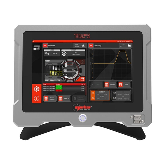
- Page 1 OPERATOR’S MANUAL T-BOX™ 2 Part Number 34474 | Issue 3 | Original Instructions (English)
-
Page 2: Table Of Contents
CONTENTS Introduction Features and Functions Before Use Updates Preparation Assembly and Connections Front Panel Connectors Rear Panel Connectors Operation Power up Select Task Screen Select AnB Screen Measure Screen Mode Selection Screen Progressive Reset Broadcast Capture Trigger Units Selection Menu Readings Screen File Browser Targets Screen... -
Page 3: Introduction
Accessories Available Part Number T-Box™ 2 to 10 way lead, for Norbar Rotary Transducers. 60216.200 T-Box™ 2 to 6 way lead, for Norbar Static & Annular Transducers. 60217.200 T-Box™ 2 to no connector (for non-Norbar transducers). 60223.200 Extensive range of torque transducers. -
Page 4: Features And Functions
Can export readings and graphs to CSV or JSON format allowing for 3rd party software integration • 2 Simultaneous transducer inputs • Automatically recognises any ‘SMART’ Norbar transducer • 5-digit resolution for all Norbar transducers • Continuous output of up to 100 readings per second via RS-232 or USB virtual serial devices •... -
Page 5: Assembly And Connections
Assembly and Connections Assembly of the T-Box™ 2 onto the Stand... -
Page 6: Front Panel Connectors
Front Panel Connectors Power Switch 2 x USB WARNING: TO TURN ON AND OFF THE T-BOX™ 2 USE EITHER THE POWER BUTTON ON THE FRONT PANEL OR THE POWER ICON IN THE T-BOX™ SOFTWARE... -
Page 7: Rear Panel Connectors
Rear Panel Connectors Port 2 Ancillary Port 2 AnB (Transducer) Power Connector Port 1 AnB (Transducer) Port 1 Ancillary RS232 OPERATION Power up To power up the T-Box™ 2, connect the DC Power connector to the back of the T-Box™ 2, and plug the other end into the mains supply. -
Page 8: Select Task Screen
Select Task Screen This is the “main menu” of the T-Box™ 2 user interface. The T-Box™ 2 UI is a multitasking interface, comprising two separate windows which can each be assigned a task (such as managing targets, capturing a graph, or measuring a transducer). You are free to pick any task for any window, at any time. -
Page 9: Select Anb Screen
Select AnB Screen The T-Box™ 2 contains two inbuilt AnB (analogue board) modules, allowing for simultaneous reading of two transducers. The Select AnB menu is used to select one of the two AnB (transducer) ports for measurement, and is opened when the user wishes to use the Measure Screen. -
Page 10: Measure Screen
Measure Screen The Measure Screen allows you to view live results and historic results from the selected AnB port as well as providing access to all the settings needed to set up and take a measurement. For most users this will be the most useful screen. - Page 11 Current Transducer Shows the currently attached TD. Tap this to re-read the Transducer when changed. If changed, any current target will be cleared. Current Units Shows the current units. Tap to open the Units Selection Screen (see Units Selection Screen) Readings A brief summary of all readings captured with this AnB port this session.
-
Page 12: Mode Selection Screen
Mode Selection Screen Mode Selection can be accessed via the Measure Screen and allows you to configure an AnB port for different types of measurement. It is important to select the correct mode for the type of tool you are testing. The filter frequency can be used for removing high frequency pulses on Pulse Tools. - Page 13 Noise Allows the user to disable noise suppression in order to capture and analyse extremely fast Suppression signals. The data supplied in the T-Box™ 2 calibration certificate is obtained with noise suppression enabled. Disabling it may result in wider uncertainties due to noise. The password to disable Noise Suppression is: transients Filter Selects an AnB module’s ADC filter frequency.
-
Page 14: Progressive Reset
Progressive Reset Normally in peak-type modes (Dial, Stall, Screwdriver, Hydraulic), the peak reading is not captured until the reading drops, and a subsequent Auto Reset or Manual Reset takes place to write the reading into memory. However, there may be circumstances where users wish to capture readings without the signal having to drop. -
Page 15: Broadcast Capture Trigger
Broadcast Capture Trigger Sometimes you may have a test to perform that involves more than one transducer, such as when using a hydraulic wrench; in this case you may be interested in measuring both torque and pressure at the same time. -
Page 16: Units Selection Menu
Units Selection Menu The Units Selection menu is where you select the current measurement units for a Measure screen. To access this screen, tap the units in the measurement dial (see Measure Screen section of the handbook, “Current Units” for a look at where to tap). Then pick a unit to switch to. If you change your mind and do not wish to switch, just pick the units you were using before. -
Page 17: Readings Screen
Readings Screen The Readings Screen is used to manage all readings from all AnBs attached to the system. You can also choose to focus on the readings from just one AnB port if you wish by filtering out other readings. Each result has a time and date, the recorded values and units, and direction (which in the case of force or pressure, may be “positive”... -
Page 18: File Browser
File Browser The File Browser allows you to browse the filesystem and manage T-Box™ data files such as Target files, Graphing captures & Readings data. Use the File Browser to copy, rename and delete these and any other files and folders, as well as copy data to or from a USB memory device. You can also directly open certain T-Box™... - Page 19 By default, the File Browser starts in the /home/user folder. This is the default directory (like the user folder on a Windows PC). You should see the Drive Icon looks like a hard disk, to indicate “internal memory” as the current data source.
-
Page 20: Targets Screen
Targets Screen The Targets Screen allows you to manage your targets. Targets specify test conditions and pass/fail parameters against which you can take measurements and store results. You can specify a target transducer reading, angle, and ISO 6789 rate timings against which to take measurements, as well as specify direction and number of readings. - Page 21 When you first open the Targets Screen, it creates an empty Targets file in the following default location: /home/user/Targets/single_targets.tbtf This file will be shown at the top right corner of the Targets Screen. If you wish to use your T-Box™ 2 like an original T-Box™, then there is nothing else you need to do, just start adding new targets and they will be saved into the default list.
-
Page 22: Target Settings
Target Settings Target settings lets you change settings pertaining to the current target file, as well as change the current target file and general settings. Current Targets File Tap this to create or load a different Targets file than the one currently displayed. -
Page 23: Target Editor
Target Editor When making a new target, the editor is designed to guide you through the steps needed to set up your target. When you first open the screen, most of the options will be hidden. First you will need to select a target type (force, pressure or torque) followed by the desired units and whether angle is required. -
Page 24: Linked Targets
Trigger Internal trigger allows angle measurement to start when the Trigger Torque value is reached External Trigger allows angle measurement to start when the Ancillary line ‘External Snug Trigger Input’ is triggered Angle Trigger Torque This sets the Trigger Torque value for Internal Trigger, at which point the angle measurement begins. -
Page 25: Graphing Screen
Graphing Screen The Graphing Screen allows you to capture graphs of transducer signals in a variety of sample rates from 1Hz to over 300Hz. When first opened it will start a live preview of transducer reading vs time for every AnB port that currently has a transducer attached. -
Page 26: Axis Configurator
Axis Configurator There are two X/Y axis pairs per graph, and by default, both will be activated if both AnB ports have a connected SMART transducer. Use the Axis Configurator to set up or disable an axis pair on a graph. X/Y Port Choose the source AnB port from which to read data... -
Page 27: Graphing Settings Menu
Graphing Settings Menu The Graphing settings menu lets you configure key graph settings and manage graph presets. Graph presets are configuration files that you can save and load to quickly set up graphs. If you regularly have to change settings when opening up the Graphing menu, then it would be worthwhile to create presets instead. -
Page 28: Settings Screen
Settings Screen The Settings Screen allows you to configure and change various system settings. Units Opens the Units Screen Serial Port Opens the Serial Port Setup Screen System Info Opens the System Info Screen Password Opens the Password Screen License Opens the License Agreement... -
Page 29: Units Screen
Units Screen This screen allows you to select available units. Disabling a unit will mean it cannot be selected from the Target screen. This can be handy if for example all your measurements are in N·m TIP: You will need to scroll this screen to see the full list of units Serial Port Here you can set up the configuration of the serial port Baud rate, Data bits, Stop bits, Parity and Flow control. -
Page 30: Software Update Procedures
AnB modules. These procedures are outlined here, but newer ones may be available alongside future updates. Visit https://www.norbar.com/Downloads/Software-Download/T-Box-2 to download the latest software for the T-Box™ 2 and the latest update procedures. Updates come in the form of .deb package files and usually are named with the “tbox_”... -
Page 31: Specification - General
±0.05% of reading ±0.073% *Using a coverage factor of k=2, to give a confidence level of approximately 95%. Resolution: 5 active digits for all Norbar transducers. Display: 10.1” Colour display with touch screen. With update rate of twenty times per second (20Hz). -
Page 32: Specification - Transducer Interface
SPECIFICATION – TRANSDUCER INTERFACE Smart Transducers Norbar ‘SMART’ transducers store the calibration data; they are available in 4 types: ‘SMART’ Transducer Description Suffix Integral Angle mV/V Figure Calibration Encoder? Supplied XXXXX.IND mV/V XXXXX.INDA mV/V With a T-Box™ 2 in XXXXX.LOG torque units With a T-Box™... -
Page 33: Specification - Ancillaries
SPECIFICATION - ANCILLARIES The Ancillaries connector contains inputs and outputs for connection to external equipment. Pin Connections Pin No Function Digital +5 V (maximum current 5 mA) External PRINT / RESET Input (Active High) Low Limit Torque Output Pass Limit Torque Output High Limit Torque Output Low Limit Angle Output Pass Limit Angle Output... -
Page 34: Analogue Output
If the output is measured against PIN 13 (0 V) the signal will always be positive, with zero torque around 2.5 V. NOTE: Some transducers (Norbar Annular type) will give a negative output change for a positive torque. This is because they are designed to measure reaction torque. -
Page 35: Specification - Serial Port
SPECIFICATION - SERIAL PORT The serial port is for sending data to a PC. See Settings Screen >> Serial Ports. Pin Connections The port is configured as DTE (Data Terminal Equipment) and conforms to RS-232-C specifications. The transmitted data voltage levels are between +5 to +9 volts and –5 to -9 volts. Pin No Function Not Connected... -
Page 36: Maintenance
Re-calibration and repair should be carried out at Norbar or by a Norbar approved agent. Repair Repair should be carried out at Norbar or by a Norbar approved agent, where all the facilities to ensure the instrument is functioning at maximum accuracy are available. -
Page 37: Troubleshooting
In ‘Serial Port Setup’ change ‘Output Limits’ to ‘Disable’. Software’ (Part No 37705.XXX). Serial data too slow. In the ‘Serial Port Setup’ change ‘Output Rate’ to a higher value NOTE: For more complex faults please contact Norbar distributor / manufacturer. -
Page 38: Example Setups
EXAMPLE SETUPS Example 1 - Click Wrench Torque Measurement For this example, we are going to check a Click Torque wrench set to 50 N·m with an accuracy of +3% / -3% 1. We will go through Transducer connection, T-Box™ 2 power up, mode selection, simple target creation, doing a measurement, and finally saving the result. -
Page 39: Example 2 - Copy Readings Folder To Memory Stick
Example 2 – Copy Readings Folder to Memory Stick In this example, we are going to copy your Readings Folder to a memory stick. Finding your Readings Folder 1. From the Selection Screen tap File Browser 2. Tap the Drive Icon 3. -
Page 40: Example 3 - Hydraulic Wrench Calibration
Example 3 - Hydraulic Wrench calibration For this example, we’re going to test a hydraulic/pneumatic wrench using a pressure transducer and a torque transducer attached to the AnB modules. Our goal is to measure the torque produced by the tool at specific pressure levels. -
Page 41: Glossary Of Terms
GLOSSARY OF TERMS Word or Term Meaning a.c. Alternating current Active From Value from which the memory modes operate Analogue to Digital Converter Analogue Board (a module which reads transducers) Auto Reset Hold Time The length of time a reading is displayed until automatically reset Calibration Capacity Transducer full scale... - Page 42 Tel + 61 (0)8 8292 9777 Tel + 86 21 6145 0368 Email enquiry@norbar.com.au Email sales@norbar.com.cn NORBAR TORQUE TOOLS INDIA PVT. LTD NORBAR TORQUE TOOLS INC Plot No A-168, Khairne Industrial Area, 36400 Biltmore Place, Willoughby, Thane Belapur Road, Mahape, Ohio, 44094 Navi Mumbai –...
Need help?
Do you have a question about the T-BOX 2 and is the answer not in the manual?
Questions and answers