Table of Contents
Advertisement
Quick Links
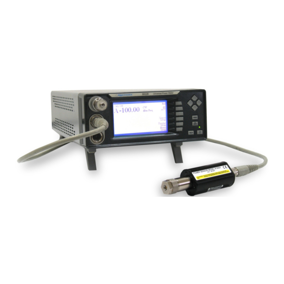
Series 8650B Universal Power Meters
Series 8650B Universal Power Meters
Operation Manual
Giga-tronics Incorporated 4650 Norris Canyon Road, San Ramon, CA 94583
925.328.4650/800.726.4442/925.328.4700 (Fax) Customer Service: 800.444.2878/925.328.4702 (Fax)
Publication 31470-001, Rev C, November 2, 2017
Advertisement
Table of Contents

Subscribe to Our Youtube Channel
Related Manuals for Giga-tronics 8650B Series


Summary of Contents for Giga-tronics 8650B Series
- Page 1 Series 8650B Universal Power Meters Series 8650B Universal Power Meters Operation Manual Giga-tronics Incorporated 4650 Norris Canyon Road, San Ramon, CA 94583 925.328.4650/800.726.4442/925.328.4700 (Fax) Customer Service: 800.444.2878/925.328.4702 (Fax) Publication 31470-001, Rev C, November 2, 2017...
- Page 2 Publication Method, Medium, Copyrights: It is the intent of Giga-tronics to publish this manual in “electronicially” as a PDF file, and delivered via CD, DVD, or other medium, including protected download, as Giga-tronics sees fit. This PDF file may be searched and printed by the end customer, but Giga-tronics does not release any resale rights to this document.
- Page 3 Series 8650B Universal Power Meters Publication 31470-001, Rev C, November 2, 2017...
- Page 4 Series 8650B Universal Power Meters About this Publication This operation manual covers the operation and performance verification of the Giga-tronics Series 8650B Universal Power Meters. Preface: In addition to a comprehensive Contents and general information about the manual, the Preface also contains a record of changes made to the manual since its publication, and a description of Special Configurations.
- Page 5 Series 8650B Universal Power Meters Conventions The following conventions are used in this product publication. Additional conventions not included here will be defined at the time of usage. Warning WARNING The WARNING statement is encased in gray and centered in the page. This calls attention to a situation, or an operating or maintenance procedure, or practice, which if not strictly corrected or observed, could result in injury or death of personnel.
- Page 6 Series 8650B Universal Power Meters Record of Publication Changes This table is provided for your convenience to maintain a permanent record of publication change data. Corrected replacement pages will be issued as TPCI (Technical Publication Change Instructions), and will be inserted at the front of the binder.
- Page 7 Series 8650B Universal Power Meters Special Configurations When the accompanying product has been configured for user-specific application(s), supplemental pages will be inserted at the front of the publication binder. Remove the indicated page(s) and replace it (them) with the furnished Special Configuration supplemental page(s). Publication 31470-001, Rev C, November 2, 2017...
-
Page 8: Table Of Contents
Series 8650B Universal Power Meters Table of Contents ..........................1-1 HAPTER NTRODUCTION 1.1 General Information ............................. 1-1 1.1.1 Features ..............................1-1 1.1.2 Environmental Standards ........................1-2 1.1.3 Power Requirements ..........................1-2 1.1.4 Items Furnished ............................. 1-2 1.1.5 Items Required ............................1-2 1.1.6 Cooling .............................. - Page 9 Series 8650B Universal Power Meters 2.3.4.3 Config ............................2-21 2.4 Measurement Guide ........................... 2-23 2.4.1 Using the Power Sweep Calibrator ...................... 2-23 2.4.2 807XXA Sensor Operation ........................2-23 2.4.3 Sensor Calibration & Zeroing ....................... 2-24 2.4.3.1 Calibration & Zeroing........................2-24 2.4.3.2 Zeroing Only ..........................
- Page 10 Series 8650B Universal Power Meters 3.1.5.3 USB ..............................3-5 3.2 SCPI Command Interface ..........................3-6 3.2.1 Sensor Calibration & Zeroing ......................... 3-6 3.2.2 Sensor & Channel Configuration ......................3-6 3.2.3 Measurement Triggering ........................3-7 3.2.4 Memory Functions ..........................3-7 3.2.5 IEEE 488.2 Required Commands ......................3-7 3.2.6 Calculate Subsystem Commands......................
- Page 11 Series 8650B Universal Power Meters 3.2.29 Halting Operation ..........................3-59 3.2.30 Language Configuration ........................3-59 3.2.31 Preset Configuration ......................... 3-60 3.2.32 Identification Commands ........................3-62 3.2.33 Calibrator Controls ..........................3-63 3.2.34 Sensor EEPROM Commands ......................3-63 3.2.35 Self-Test ............................. 3-64 3.2.36 Error Messages ..........................
- Page 12 Series 8650B Universal Power Meters 3.11.1.1 External Gating Mode ......................... 3-93 3.11.1.2 External Trigger Mode ........................ 3-93 3.11.1.3 Internal Burst Edge Detection ....................3-93 3.11.2 Time Gating Mode ..........................3-94 3.11.2.1 Gate A or B..........................3-94 3.11.2.2 OFF or GATE or TRIGGER or EDGE ....................3-94 3.11.2.3 INVERT or NONINVERT .......................
- Page 13 Series 8650B Universal Power Meters 3.17.2.3 For the Fast Modulated Mode ....................3-110 3.17.3 Fast Buffered Mode ......................... 3-111 3.17.3.1 Fast Buffered Mode Notes ....................... 3-112 3.17.4 Swift Mode ............................3-113 3.17.4.1 Swift Mode Notes ........................3-113 3.17.4.2 Example Programs ........................3-114 3.17.5 Fast Modulated Mode ........................
- Page 14 Series 8650B Universal Power Meters 3.19.17.1 Enabling & Disabling V F ....................3-142 PROP 3.19.17.2 Configuring V F ........................3-143 PROP 3.19.18 Zeroing ............................3-144 3.19.19 Histograms, CDF & CCDF ....................... 3-145 3.19.19.1 Setting Histogram Mode Intervals..................3-145 3.19.19.2 Histogram Range ........................3-145 3.19.19.3 Enabling &...
- Page 15 Series 8650B Universal Power Meters ............................. C-1 PPENDIX PTIONS C.1 Introduction ..............................C-1 C.2 Options ................................. C-1 C.2.1 Option 01: Rack Mount Kit ........................C-1 C.2.2 Option 03: Rear Panel Sensor In & Calibrator Out Connectors (8651B) ..........C-1 C.2.3 Option 04: Rear Panel Sensor In & Calibrator Out Connectors (8652B) ..........C-2 C.2.4 Option 05: Soft Carrying Case .......................
- Page 16 Series 8650B Universal Power Meters List of Figures Figure 1-1: Fuse Holder ............................1-5 Figure 1-2: Series 8650B Rear Panel ........................1-6 Figure 2-1:8652B Front Panel Layout ........................2-1 Figure 2-2: Main Menu ............................2-4 Figure 2-3: Power Meter Configuration Display ..................... 2-6 Figure 2-4: Strip Chart Illustration ..........................
- Page 17 Series 8650B Universal Power Meters List of Tables Table 1-1: Series 8650B Rear Panel I/O Connectors....................1-6 Table 1-2: Measurement Rates ..........................1-11 Table 3-1: Implemented IEEE Standards ........................ 3-1 Table 3-2: IEEE Required Command Codes ......................3-7 Table 3-3: SCPI Command Syntax ......................... 3-15 Table 3-4: SCPI Status Byte Register ........................
-
Page 19: Chapter 1 Introduction
The 8650B and the Series 806XXA or Series 807XXA power sensors offer enhanced performance in the measurement of complex modulation signals in the communication industry. The 8650B maintains the functionality of Giga-tronics 8650A, 8540B, and 8540C power meters and compatibility with all existing power sensor models. -
Page 20: Environmental Standards
Series 8650B Universal Power Meters 1.1.2 Environmental Standards The Series 8650B instruments are type tested to MIL-PRF-28800F, Class 3 for all departments and agencies of the Department of Defense applications except as follows: • Operating temperature range is 0 °C to 55 °C (Calibrator operating temperature range is 5 °C to 35 °C) •... -
Page 21: Receiving Inspection
Mark the outside of the package: FRAGILE — DELICATE INSTRUMENT If corresponding with the factory or the local Giga-tronics sales office regarding reshipment, please provide the model and serial number. If the instrument is being returned for repair, be sure to enclose all relevant information regarding the problem that has been found. -
Page 22: Installation
Series 8650B Universal Power Meters 1.2 Installation Select the correct operating voltage and install the proper fuse in this housing. Refer to Section 1.2.2, Line Voltage and Fuse Selection for instructions on how to select the voltage and replace the fuse. Observe the following Safety Precautions when installing the Series 8650B Universal Power Meter. -
Page 23: Power
Introduction 1.2.2 Power The instrument is shipped in an operational condition and no special installation procedures are required except to check and/or set the operating voltage and fuse selection as described in the following. When the instrument is shipped from the factory, it is set for a power line voltage (120 Vac for domestic destinations). -
Page 24: Interface (Rear Panel)
Series 8650B Universal Power Meters 1.2.4 Interface (Rear Panel) The rear panels for the 8651B and 8652B are identical and are illustrated in Figure 1-2. Any options that have been installed in the unit will be noted on the serial number tag. Refer to the Special Configurations section in the preface of this manual for detailed information about installed options or other special configurations. -
Page 25: Specifications
Introduction 1.3 Specifications 1.3.1 Power Meter Frequency Range 10 MHz to 50 GHz Power Range -70 dBm to +47 dBm (100 pW to 50 Watt) Single Sensor Dynamic Range CW Power Sensors 90 dB Peak Power Sensors 50 dB CW Mode; 40 dB Peak Mode Modulation Sensors 87 dB CW Mode;... -
Page 26: Accuracy
Series 8650B Universal Power Meters Sampling CW Mode & Modulation Mode 2.5 to 5.0 MHz, Asynchronous Analog Bandwidth CW Mode ≥3 kHz Modulation Mode >10 MHz Time Gated Measurements Gate Time 5 µs to 100 ms Trigger Delay 0 to 100 ms Holdoff Time 0 to 100 ms External Trigger Polarity... - Page 27 Introduction 800 MHz to 1 GHz Synthesizer (Option 12) Power Range +20 to -30 dBm, settable in 1dB steps Frequency 800 MHz to 1 GHz, settable in 1MHz steps Power Stability < 0.1 dB/hour Frequency Accuracy ±0.05% NOTE: Power accuracy for Option 12 is only guaranteed while in calibration mode at 1 GHz, 0 dBm. Instrumentation Linearity ±0.02 dB over any 20 dB range from -70 to +16 dBm ±0.02 dB (±0.05 dB/dB) from +16 to +20 dBm...
- Page 28 Series 8650B Universal Power Meters Instrumentation Linearity (continued) <±100 pW with all CW Power Sensors <±200 pW with Series 804XXA and 806XXA Modulation Power Zero Drift Sensors <±400 pW with Series 807XXA Modulation Power Sensors <±50 pW with all CW Power Sensors <±100 pW with Series 804XXA and 806XXA Modulation Power Noise Sensors...
-
Page 29: Measurement Rates
Introduction 1.3.3 Measurement Rates The following Table illustrates typical maximum measurement rates for different measurement collection modes. The rate of measurement depends on several factors including the controller speed and the number of averages. Table 1-2: Measurement Rates Measurement Collection Mode Readings per Second Readings per Second (CW Measurement) -
Page 30: Remote Operation
Series 8650B Universal Power Meters 1.3.4 Remote Operation GPIB, USB, and LAN Interface All front panel operations and some remote-only operations can be remotely programmed using SCPI (Standard Commands for Programmable Instruments), IEEE 488.2 and IEC-625 coding. GPIB Interrupts SRQs are generated for the following conditions: Power Up, Front Panel key actuation, Operation Complete and Illegal Command. -
Page 31: General Specifications
Introduction LAN Connector (RJ45) Interfaces the power meter to a Local Area Network for remote programming using SCPI, IEEE 488.2 and IEC-625 coding. RS-232 Connector (DB-9) Interfaces the power meter to serial communications equipment, using RS-232 format. 1.3.7 General Specifications Temperature Range Operating 0 to 55 °C (32 to 132 °F) -
Page 33: Chapter 2 Front Panel Operation
Front Panel Operation Chapter 2 Front Panel Operation 2.1 Introduction This chapter describes how to operate the Series 8650B Universal Power Meters using the front panel. It includes descriptions of the front and rear panels, configuration, display menus and practical applications. Use the items below for reference. -
Page 34: Front Panel Layout Descriptions
Series 8650B Universal Power Meters 2.2.1 Front Panel Layout Descriptions The following are the descriptions based on the call out numbers for Figure 2-1. 1 - Dedicated Hardkeys The dedicated hardkeys are located on the right side of the front panel and function as described below. In this manual, instructions to press a dedicated hardkey are with the appropriate key title in bold uppercase enclosed in brackets, such as ‘press [CAL/ZERO] to calibrate a power sensor’... - Page 35 Front Panel Operation CAUTION To avoid losing some current settings and ensuring that the meter powers up properly, observe the following procedures: 1) Remove AC Power to the rear panel only after at least 1 second has lapsed from the time the front panel ON/OFF switch has been pressed to turn off the meter.
-
Page 36: Front Panel Applications
Series 8650B Universal Power Meters 2.3 Front Panel Applications The Series 8650B screen normally displays measurement data, but it also displays the setup and configuration menus for the meter, display and sensor. The setup menus are dynamic; the display adapts to the current operating mode and the type of sensors and other peripheral connections. -
Page 37: Meter Setup
Front Panel Operation 2.3.1 Meter Setup The Meter Setup menu provides the means to configure the meter operating mode, and to store and recall setups. From the Main menu, press [Meter Setup] to display the Meter Setup menu. Press the softkey for the function to perform. -
Page 38: Config
Series 8650B Universal Power Meters 2.3.1.2 Config Press [Config] from the Meter Setup menu to display the Power Meter Configuration menu (See Figure 2-3). Access this menu to configure the following: GPIB (Mode & Address) • • V/F (V F) Input & Scale Factor PROP •... - Page 39 Front Panel Operation 4. Press [OK] to accept the changes or [Cancel] to cancel the changes and return to the Power Meter Configuration menu. V/F In The V/F (V F) input accepts a frequency referenced to 0 Vdc, which the power meter uses to determine and PROP apply the appropriate correction factors (Stored in the sensor EEPROM).
-
Page 40: Figure 2-4: Strip Chart Illustration
Series 8650B Universal Power Meters Strip Chart The Strip Chart function plots measurements on the screen over a fixed period or continuously. The X-axis displays time from the start of a measurement to a selective period of 1 to 200 minutes. While running, the adaptive auto-scaled high and low plotting limits are displayed. - Page 41 Front Panel Operation Sound A speaker within the chassis produces audible clicks and tones to register keystrokes and to draw attention to certain conditions. For example, if a limit has been exceeded or a calibration process has been completed. From the Power Meter Configuration menu, move the cursor to the Sound option and press [Config].
-
Page 42: Figure 2-5: External Gating Illustration
Series 8650B Universal Power Meters T Gate The Time Gate mode supplies a digital control voltage to enable or disable readings from any one or all sensors. Thus, the mode limits a power measurement to a defined interval that is controlled by a start time and duration. The start time begins after a programmable delay following an external or internal trigger. -
Page 43: Figure 2-6: External Triggering Illustration
Front Panel Operation b. External Trigger Figure 2-6 illustrates the Time Gated measurement parameters with an external trigger. When an external trigger is input (Point A in Figure 2-6), it starts the Trigger Delay. At the end of the Trigger Delay, the Gated Time measurement starts and lasts until its preselected time expires. -
Page 44: Figure 2-7: Burst Edge Configuration Illustration
Series 8650B Universal Power Meters 1.) Press [Ext Trigger Rising] or [Ext Trigger Falling] to set the parameters of the external trigger. The settings are: Delay Gate Time Holdoff Upon entering the External Trigger setup, a burst profile will display at the bottom of the screen. If the following specifications are not met, the profile may be inaccurate or not displayed at all: a.) The time from between trigger edges is the period of the trigger. -
Page 45: Figure 2-8: Histogram Illustration
Front Panel Operation Histogram The Histogram feature displays graphical views of accumulated data distribution over a selective period of time (See Figure 2-8). From the Power Meter Configuration menu move the cursor to the Histogram option and press [Config]. 1. Press [Select Source] and select the input channel (8652B Only) or display the line number. 2. -
Page 46: Figure 2-9: Cdf Curve Illustration
Series 8650B Universal Power Meters 4. Move the cursor along the slope of any curve to display, below the graph, the cursor position, the power level and the corresponding percentage of time the signal is above or below that level. Figure 2-9: CDF Curve Illustration Figure 2-10: CCDF Curve Illustration Ethernet... -
Page 47: Sto/Rcl
Front Panel Operation 5. Press [Subnet Mask] to manually set the Subnet Mask. The Subnet Mask Config menu will display for configuration of the Subnet Mask. Select the desired address with the soft-keys and cursor keys. Press [OK] to accept the Subnet Mask. 6. -
Page 48: Display Setup
Series 8650B Universal Power Meters 2.3.2 Display Setup Use this option to configure the data and format that will display on each line of the screen. From the Main Menu, press [Display Setup] to select the Configure Display menu (See Figure 2-11). This screen is the same as the Main Menu except the control items are changed to display line configuration options. -
Page 49: Line Configuration
Front Panel Operation 2.3.2.1 Line Configuration Select the line to be configured by pressing the corresponding [Line n] softkey. The menu in Figure 2-12 will display. The current configuration of the selected source displays in the large window at the bottom of the screen. - Page 50 Series 8650B Universal Power Meters d. Off: Select this option to turn the line off. When a line is turned off, it will not be available as a source for Line n. For example, if Line 4 is turned off, setting Line 3 cannot read the minimum/maximum values of line 4.
-
Page 51: More Options
Front Panel Operation 2.3.2.2 More Options 1. Select [More Options] from the Configure Display menu (See Figure 2-11) to set the brightness of the display screen. The adjustments, made with the cursor keys, are interactive, allowing the observation of the brightness. -
Page 52: Sensor Setup
Series 8650B Universal Power Meters 2.3.4 Sensor Setup Sensor configuration enables selecting the operating mode of sensors, or to select the parameters for averaging time-based measurements. From the Main Menu, press [Sensor Setup] to display the installed sensor data and configuration options (See Figure 2-13). -
Page 53: Offset
Front Panel Operation 2.3.4.2 Offset Select this option to enter an offset value in dB when an attenuator or amplifier is installed before the sensor input. From the Sensor Setup menu: 1. Press [Offset] and enter the value of the offset with the cursor keys. 2. - Page 54 Series 8650B Universal Power Meters Modulation Sensors Modulation sensors can be used in CW, Modulated Average Power (MAP), Peak Average Power (PAP) and Burst Average Power (BAP) modes. 1. From the Sensor Setup menu select the Modulation sensor with the cursor keys. 2.
-
Page 55: Measurement Guide
Front Panel Operation 2.4 Measurement Guide This section presents guidelines for practical applications of the 8650B. See Section 2.4.9 for mode restrictions. 2.4.1 Using the Power Sweep Calibrator The Power Sweep Calibrator automatically calibrates the power sensor to the power meter. The power sweep operates from -30 to +20 dBm (the complete, non-square-law operating region) and transfers the inherent linearity of an internal, thermal-based detector to the balanced diode sensors. -
Page 56: Sensor Calibration & Zeroing
Series 8650B Universal Power Meters 2.4.3 Sensor Calibration & Zeroing All sensors must be calibrated and zeroed before making measurements. 2.4.3.1 Calibration & Zeroing 1. Connect the sensor to be calibrated from Channel A or B to the Calibrator output (See Figure 2-14). NOTE: Connector sensor to the Calibrator connector after the power meter is turned on. -
Page 57: Zeroing Only
15 minutes for moderate initial temperature differences. 2.4.3.3 Calibration & Zeroing (High Power Sensors with Removable Attenuators) When using a Giga-tronics high power sensor with external attenuator, Giga-tronics power meters automatically recognize the sensor type and compensates for the attenuation factor. However when performing the front panel calibration, be sure to remove the attenuator before connecting to the calibrator port. -
Page 58: Low Level Performance Check
Series 8650B Universal Power Meters 2.4.3.4 Low Level Performance Check This procedure provides a quick-check list for evaluating meter/sensor performance for low-level measurements. It is not intended to verify performance of specifications such as Noise, Temperature Coefficient and Zero Set. For complete verification, please refer to Chapter 4. 1. -
Page 59: Measuring Source Output Power
Front Panel Operation 2.4.4 Measuring Source Output Power To measure the source output power: 1. Connect the power sensor to the RF output of the microwave source. 2. Verify that the microwave source RF output is ON. 3. Press [FREQ]; enter the operating frequency (use the cursor keys to adjust the value), and press [OK]. 4. -
Page 60: High Power Level Measurements
+37 dBm can be measured directly without the use of an attenuator. 2.4.7 Modulated Measurement Modes The 8650B series of power meters expands upon the capabilities of the previous 8540 power meters in a number of ways. In the past, power measurements of modulated signals (Pulse, Multi-tone, AM, etc.) required that the signals be attenuated to levels less than -20 dBm to avoid errors due to sensor nonlinearity. -
Page 61: Pap Mode
Front Panel Operation 2.4.7.2 PAP Mode The Pulse Average Power (PAP) mode is similar to the MAP mode, but it measures pulse-modulated signals having a known duty cycle. To specify this duty cycle and the 8650B will automatically correct the measurements so that the displayed readings indicate the peak RF power during pulse ON periods. - Page 62 Series 8650B Universal Power Meters In BAP mode, the 8650B automatically determines which portions of the signal are in the pulse and which are not. In computing the average power, the 8650B uses only those portions that are within the pulse. The result is that, independent of the signal’s pulse duty cycle, the meter always reads the average power in the pulse or burst.
-
Page 63: Measurement Collection Modes
Front Panel Operation 2.4.8 Measurement Collection Modes Using a wide range of CW and Modulation Power Sensors and the GPIB fast measurement collection modes, the Series 8650B meters provide typical reading speeds of 1750 readings per second in the GPIB Swift Freerun mode, 800 readings per second in the GPIB Fast Modulated mode, and 26,000 readings per second in the GPIB Fast Buffered mode. -
Page 64: Figure 2-17: Delay & Delay Offsets
Series 8650B Universal Power Meters Peak power measurements are made by sampling the RF input at a point which is defined by a trigger level, a delay, and a delay offset (See Figure 2-17). The initial triggering event occurs when the power input (or in the case of external triggering, a voltage input) reaches a threshold, which has been defined as the trigger level by the user. -
Page 65: Mode Restrictions
Front Panel Operation 2.4.9 Mode Restrictions In specific modes the 8650B has particular restrictions on its operation: • In the remote operation GPIB fast measurement collection modes, GPIB Swift mode and GPIB Fast Buffered mode (also referred to as Burst mode), it is not possible to make measurements which compare the two channels. - Page 66 Series 8650B Universal Power Meters For two-tone testing, small errors in the measurement will result when the carriers are separated by more than the specified bandwidth of the sensor. The amount of error is also a function of average power level. For average power less than about -20 dBm, there is no modulation-induced measurement error at any tone separation.
-
Page 67: Peak Hold
Front Panel Operation 2.4.12 Peak Hold When the Peak Hold feature is selected, the 8650B displays the highest instantaneous power measured from the time the feature is enabled until it is reset by the user. In other words, the displayed value tracks the measured value only when the measured value is rising to a new maximum. -
Page 68: Crest Factor
Series 8650B Universal Power Meters 2.4.13 Crest Factor The Crest Factor feature is very similar to the peak hold feature, in that it holds on to the maximum level until a reset occurs, but in this case the displayed value is expressed (in dB) as a ratio of the held maximum power to the average power. - Page 69 Front Panel Operation Like the Peak Hold feature, the Crest Factor feature also has the same minimum average power level restriction of -20 dBm. This has been implemented to increase accuracy and maintain wide bandwidth of Crest Factor measurement over the peak power range of -20 dBm to +20 dBm. The Crest Factor selection will also affect Histogram measurement if there is power below -20 dBm.
-
Page 70: Burst Signal Measurements
Series 8650B Universal Power Meters 2.4.14 Burst Signal Measurements In a burst signal, the RF is pulsed on and off (i.e., pulse modulated). Often, the RF is modulated during the pulse on time. Typical examples are TDMA digital cellular telephone formats such as NADC, PDC, and GSM. These formats and many others produce amplitude modulation of the RF during bursts. -
Page 71: Burst Start Exclude, Burst End Exclude
Front Panel Operation 2.4.15 Burst Start Exclude, Burst End Exclude When measuring burst signals, it is sometimes desirable to mask the beginning or the end of a burst so that overshoot and other distortions do not affect the reading. The Burst Start Exclude and Burst End Exclude features make it possible for BAP mode measurements to exclude the beginning or the end of a burst in this way. -
Page 72: Burst Dropout
Series 8650B Universal Power Meters 2.4.16 Burst Dropout In the BAP mode, average power is measured only during bursts. Because, in this mode, the bursts are automatically detected by the power meter, the user need not be aware of the burst repetition rate in order to make the measurement. -
Page 73: Optimizing Measurement Speed
Front Panel Operation 2.4.17 Optimizing Measurement Speed In many power measurement situations, measurement speed is defined in terms of settling time following a step change in average power. In other words, it is desired to know the average power level within some specified tolerance as quickly as possible following a power level change. -
Page 74: Peak Power Measurements
Series 8650B Universal Power Meters 2.4.18 Peak Power Measurements Peak power sensors directly measure the amplitude of pulsed microwave signals. The direct sampling technique is more accurate than traditional duty cycle correction methods. The sample position can be displayed on an oscilloscope. -
Page 75: Improving Accuracy
Front Panel Operation 2.4.20 Improving Accuracy Mismatch uncertainty is the largest source of error in power measurement. The 6 dB pad that is used in the attenuator calibration procedure above reduces mismatch uncertainty by effectively improving the return loss (or reducing the SWR) of the source. Mismatch uncertainty is large when a device has a poor impedance match relative to 50 Ω. -
Page 76: Performance Verification
Series 8650B Universal Power Meters 2.4.21 Performance Verification Verifying accuracy and calibrating test equipment are essential to microwave engineers and technicians. Accurate, repeatable measurements are required for validating designs, certifying calibrations, making engineering decisions, approving product components, certifying standards and verifying performance specifications (See also Chapter 4). -
Page 77: Sources Of Error
Front Panel Operation 2.4.22 Sources of Error In the previous accuracy verification procedure, there are four sources of error: • Source output level variation • Power splitter output tracking • Power meter X total measurement uncertainty • Power meter Y total measurement uncertainty Worst case uncertainty, which should be used for calibration purposes, is the arithmetic sum of all four of these sources of error. -
Page 79: Chapter 3 Remote Operation
The 8650B power meter uses standard protocols for communication over the GPIB. Commands conform to IEEE 488.1 or IEEE 488.2 guidelines. Four emulation modes (Giga-tronics 8540, HP436, HP437 and HP438) are available for users of power meters who cannot rewrite their application software. -
Page 80: Clear Device Over Gpib
Series 8650B Universal Power Meters 3.1.1.1 Clear Device over GPIB The interface command CLEAR 713 resets the GPIB and sets the 8650B to its preset condition. 3.1.1.2 Clear Interface over GPIB The interface command ABORT 7 resets the GPIB without resetting the 8650B to its preset condition. The 8650B will not be addressed after the abort. -
Page 81: Polling Over Gpib
Remote Operation 3.1.2 Polling over GPIB The GPIB supports parallel and serial polling. The example programs below show how to use the parallel and serial poll capabilities of the 8650B to determine when a requested zeroing operation is completed. 3.1.2.1 Parallel Polling over GPIB Ppoll_zero ! zero using parallel poll PRINT entering parallel poll zero routine... -
Page 82: Data Output Formats
Series 8650B Universal Power Meters 3.1.3 Data Output Formats The data output format for the standard measurement collection mode is: ±D.DDDDE±NNCRLF ±: Sign of the Mantissa D.DDDD: Mantissa (5 digits) Exponent (indicates that an exponent follows) ±: Sign of the Exponent Magnitude of the Exponent Carriage Return Line Feed... -
Page 83: Remote Connection Configuration
Remote Operation 3.1.5 Remote Connection Configuration NOTE: Always reboot the 8650B when changing the remote connection interface. 3.1.5.1 GPIB Configure the 8650B for remote operation over GPIB: 1. Select the interface command mode under the Mode selction of the GPIB Configuration menu (see Section 2.3.1.2 for details) 2. -
Page 84: Scpi Command Interface
Series 8650B Universal Power Meters 3.2 SCPI Command Interface This section details operation of the 8650B power meter using the SCPI (Standard Communications for Programmable Instruments) interface commands. A SCPI command reference is presented in Table 3-3 and the sections that follow. SCPI commands promote consistency in definition of a common instrument control and measurement command language. -
Page 85: Measurement Triggering
Remote Operation 3.2.3 Measurement Triggering The power meter uses the Trigger Subsystem to trigger measurements in two different operational modes: a normal mode which maximizes the instrument’s functionality, and GPIB Swift and GPIB Burst (also referred to as Fast Buffered) modes that maximize the power measurement rate over GPIB. 3.2.4 Memory Functions The MEMory commands control the configuration of the automated Voltage-Proportional-to-Frequency (V PROP... -
Page 86: Calculate Subsystem Commands
Series 8650B Universal Power Meters 3.2.6 Calculate Subsystem Commands Calculate commands specify and query the configuration of power measurement channels, known in SCPI references as Software Calculation Channels, and in this publication as “channels”. See Section 3.2.7 for sensor- specific configuration and measurement function control. The query form of CALC#?, with # replaced by the channel modifier (1 or 2), returns the current configuration status for that channel. -
Page 87: Figure 3-3: Additional Calculate Subsystem Commands (Modulation Sensors)
Remote Operation Figure 3-3: Additional CALCulate Subsystem Commands (Modulation Sensors) Publication 31470-001, Rev C, November 2, 2017... -
Page 88: Sense Subsystem Commands
Series 8650B Universal Power Meters 3.2.7 Sense Subsystem Commands The SENSe subsystem configuration commands, illustrated in Figure 3-4, apply to individual sensors. These commands alter the value of the measured power level according to the sensor’s characteristics. For example, measured power levels can be offset for attenuators or couplers in the measurement path so that the power data reading reflects the power level at the measurement point of interest. - Page 89 8650B is triggered. Please note that the SENSe:TRIGger commands are not instrument triggers, but Peak Power Sensor configuration controls. SENSe:TRIGger functions apply only to Giga-tronics Peak Power Sensors. The DELay and LEVel functions of these Peak Power Sensor controls apply to the 8035XA Peak Power Sensors. The AVERage and CORRection commands apply to all 803XXA Series CW &...
-
Page 90: Trigger Subsystem Commands
Series 8650B Universal Power Meters 3.2.8 Trigger Subsystem Commands The TRIGger Subsystem is divided into two sections; Instrument Measurement Event Triggering and Special Triggering Configuration commands for the GPIB fast-reading buffered data modes (GPIB Burst and GPIB Swift modes). The TRIGger command tree is illustrated in Figure 3-5. Figure 3-5: TRIGger subsystem Command Tree The query form of these commands, TRIG?, will return the instrument’s current configuration status. -
Page 91: Figure 3-6: Sense Subsystem Command Tree For Configuring Modulation Sensors
Remote Operation Figure 3-6: SENSe Subsystem Command Tree for Configuring Modulation Sensors Figure 3-7: SENSe Subsystem Command Tree for Configuring Modulation Sensor Gate Settings Publication 31470-001, Rev C, November 2, 2017 3-13... -
Page 92: Scpi Command Syntax
Series 8650B Universal Power Meters 3.2.9 SCPI Command Syntax The following conventions are used with the SCPI commands in this publication. Some commands will be in both upper- and lower-case, such as CALCulate and MEMory. The uppercase is the required input. The whole word can be used if desired. -
Page 93: Table 3-3: Scpi Command Syntax
Remote Operation Table 3-3: SCPI Command Syntax Command Syntax Function Section SCPI Required Codes *CLS Clear SRQ and status byte registers 3.2.24.5 *ESE n Set Event Status Enable Register to value n 3.2.24.2 *ESE? Query form is available *ESR? Query Event Status Register value 3.2.24.2 *IDN? Query instrument mfgr and model number... - Page 94 Series 8650B Universal Power Meters Table 3-3: SCPI Command Syntax Command Syntax Function Section CALCulate<channel 1 to 4>:MAXimum[:MAGnitude]? Query the channel maximum value in dBm 3.2.25 CALCulate<channel 1 to 4>:MINimum:STATespace<ON | OFF> Enable/Disable the channel min. value monitoring 3.2.25 CALCulate<channel 1 to 4>:MINimum[:MAGnitude]? Query the channel minimum value in dBm 3.2.25 CALCulate<channel 1 to 4>:REFerence:STATespace<ON | OFF>...
- Page 95 Remote Operation Table 3-3: SCPI Command Syntax Command Syntax Function Section SENSe<sensor 1 or 2>:CONFig:BAP Enable BAP mode on the specified sensor 3.2.11 SENSe<sensor 1 or 2>:CONFig:BAP:BEEXcludespace<samples> Set the number of BAP mode burst end exclude 3.2.11 samples SENSe<sensor 1 or 2>:CONFig:BAP:BEEXclude? Query the number of BAP mode burst end exclude 3.2.11 samples...
- Page 96 Series 8650B Universal Power Meters Table 3-3: SCPI Command Syntax Command Syntax Function Section SENSe<sensor 1 or 2>:TRIGger:DELay:STATespace<ON | OFF> Enable/Disable the Peak sensor delay function 3.2.19 SENSe<sensor 1 or 2>:TRIGger:LEVel[:MAGnitude]space Set the Peak sensor trigger level in volts or dBm 3.2.19 <peak sensor trigger level in volts or dBm>...
-
Page 97: Sensor Calibration & Zeroing
Remote Operation 3.2.10 Sensor Calibration & Zeroing CALibrate CALibrate:STATe? CALibrate:ZERO SENSe:TEMPerature? 3.2.10.1 Sensor Calibration The CALibration commands for sensor calibration and zeroing are important for accurate power measurement results. Be sure to perform the sensor calibration prior to beginning measurement operation or channel configuration. -
Page 98: Sensor Zero
Series 8650B Universal Power Meters 3.2.10.2 Sensor Zero Zeroing automatically accounts for ground noise and other noise in the measurement system. Measurements will be sensitive to noise-induced errors only in the lowest 15 dB of the sensor dynamic range. Be sure to turn off the signal going into the sensor during zeroing, otherwise a failure will be indicated. -
Page 99: Sensor Configuration Commands
Remote Operation 3.2.11 Sensor Configuration Commands SENSe:CONFig? SENSe:CONFig:CW SENSe:CONFig:MAP SENSe:CONFig:MAP:UNSYnchronized SENSe:CONFig:BAP SENSe:CONFig:PAP The following commands are for sensor configuration. SENSe:CONFig? Syntax: SENSe<sensor 1 or 2>:CONFig? SENS1:CONF? ! QUERIES SENSOR 1 CONFIGURATION Example: Description: Queries sensor configuration on specified input. Response is character response data: CW | MAP | MAPU | BAP | PAP | PEAK |UNCAL | NOSENSOR. - Page 100 Series 8650B Universal Power Meters SENSe:CONFig:BAP Syntax: SENSe<sensor 1 or 2>:CONFig:BAP SENS1:CONF:BAP ! ENABLES BAP MODE FOR SENSOR 1 Example: Description: Configures a modulation sensor for BAP (Burst Average Power) mode on the specified input. This command does not affect the burst start or end exclude or dropout tolerance parameters. The default values, set by *RST, correspond to the “automatic”...
-
Page 101: Sensor Gate Commands
Remote Operation 3.2.12 Sensor Gate Commands SENSe:GATE:MODE SENSe:GATE:POLarity SENSe:GATE:DELay SENSe:GATE:DURation SENSe:GATE:HOLDoff The following commands are for sensor gate settings. NOTE: The Time Gate feature operates only with modulation sensors. SENSe:GATE:MODE Syntax: SENSe<sensor 1 or 2>:GATE:MODEspace<OFF, GATE, TRIGger or EDGE> SENS1:GATE:MODE GATE ! SETS SENSOR 1 TO GATE TIME GATING MODE Example:... - Page 102 Series 8650B Universal Power Meters SENSe:GATE:DELay Syntax: SENSe<sensor 1 or 2>:GATE:DELayspace<time> (Where <time> is in the range 0 to 100 ms with a resolution of 1 µs, where 0 represents some minimum nonzero delay time) SENS1:GATE:DELAY 20E-3 ! SETS THE SENSOR 1 TIME GATE DELAY TO 20 mS Example: SENS1:GATE:DEL? ! REQUESTS SENSOR 1 TIME GATE DELAY SETTING...
-
Page 103: Reading Power Measurements
Remote Operation 3.2.13 Reading Power Measurements FETCh? MEASure? READ? These commands return measurement data from the 8650B. During Normal mode the data will be single measurement values. During GPIB Swift or GPIB Burst modes, the data will be an array of values. Generally, it is a single array if one sensor is connected and calibrated and a dual array if two sensors are connected and calibrated. -
Page 104: Special Errors
Series 8650B Universal Power Meters READ? Syntax: READ<channel 1 to 4>[:POWer]? READ2? ! TRIGGERS AND MEASURES CHANNEL 2 POWER Example: ! IN NORMAL MODE Response: A power measurement. Description: The READ#? query command triggers the measurement of the specified channel and sends the data to the controller. -
Page 105: Instrument Triggering
Remote Operation 3.2.14 Instrument Triggering *TRG TRIGger[:IMMediate] TRIGger:SOURce TRIGger:MODE TRIGger:DELay TRIGger:COUNt *WAI These SCPI commands trigger the measurement cycle. They do not configure or provide triggering for Peak Power Sensors. Those commands are defined in Section 3.2.19. For power meter operation, the TRIGger Subsystem is divided into two sections;... - Page 106 Series 8650B Universal Power Meters *TRG Syntax: *TRG *TRG ! BUS TRIGGER EVENT Example: Description: *TRG is an IEEE 488.2 compatible programming command to initiate BUS triggered measurements. The power meter interprets *TRG as a BUS source for instrument triggering events.
- Page 107 Remote Operation TRIGger:DELay TRIGger:DELayspace<delay time between buffered readings in sec, 0.000 to 0.050> Syntax: TRIG:DEL 5E-3 ! SETS THE BURST MODE MEASUREMENT TIME TO Example: ! 5 mS BETWEEN MEASUREMENTS TRIG:DEL 0 ! SETS THE BURST MODE MEASUREMENT TO THE Example 2: ! MAXIMUM MEASUREMENT RATE Description:...
-
Page 108: Arming The Triggering Cycle
Series 8650B Universal Power Meters 3.2.15 Arming the Triggering Cycle INITiate:CONTinuous INITiate[:IMMediate] The INITiate commands enable the power meter to acquire measurement data at the next instrument trigger. In the absence of an instrument signal, the 8650B is placed in the waiting-for-trigger-state. The default configuration is continuous initiation off, INITiate:CONTinuation OFF. -
Page 109: Channel Configuration
Remote Operation 3.2.16 Channel Configuration CALCulate:POWer CALCulate:RATio CALCulate:DIFFerence CALCulate? CALCulate:UNIT CALCulate:STATe CALCulate:CrestFACtor:STATe CALCulate:CrestFACtor:DATa? CALCulate:PeakHOLd:STATe CALCulate:PeakHOLd:DATa? CALCulate:StatisicalFUNctions:STATe CALCulate:StatisicalFUNctions:DATa? CALCulate:POWer Syntax: CALCulate<channel 1 to 4>[:CHANnel]:POWerspace<sensor 1 or 2> CALC2:POW 1 ! CONFIGURES CHANNEL 2 TO MEASURES SENSOR 1 POWER Example: Description:... - Page 110 Series 8650B Universal Power Meters CALCulate? Syntax: CALCulate<channel 1 to 4>[:FUNCtion]? CALC2? ! QUERIES CHANNEL 2 SENSOR CONFIGURATION Example: Response: POW #, RAT #,#, or DIF #,# Description: This command returns the current channel configuration. This command is a query format only. CALCulate:UNIT Syntax: CALCulate<channel 1 to 4>:UNIT[:POWer]space<data units selection, DBM or W>...
- Page 111 Remote Operation CALCulate:PeakHOLd:STATe Syntax: CALCulate<channel 1 to 4>PeakHOLd:STATespace<ON | OFF> CALC1:PHOL:STAT ON ! ENABLES THE CHANNEL 1 PEAK HOLD FUNCTION Example: CALC1:PHOL:STAT? ! QUERIES CHANNEL 1 PEAK HOLD FUNCTION STATUS Example 2: Description: Enables or disables the Peak Hold function on the specified channel. The Peak Hold feature causes the measured value to hold at the highest instantaneous power measured from the time the feature is enabled until it is reset (the measured value changes only when it is rising to a new maximum, or when it is reset).
-
Page 112: Cal Factor Correction
Power Sensors have a measurable frequency response. During manufacture, this response is calibrated at predetermined frequency intervals. Instead of printing the data on the sensor label, each Giga-tronics power sensor includes a built-in EEPROM which has been programmed with the frequency calibration factor data for that particular power sensor. -
Page 113: Cal Factor Error Control
F output is 0.0 V. Then the slope relationship is PROP entered in the form of a value representing the V/Hz relationship. If, for example, source is a Giga-tronics GT-2520B Series Signal Generator, this relationship is 0.5 V/GHz or 5e-8 V/Hz. MEMory:FREQuency Syntax: MEMory[:TABLe]:FREQuencyspace<Start frequency>... -
Page 114: High Speed Measurements
Series 8650B Universal Power Meters 3.2.18 High Speed Measurements CALCulate:DATA? CALCulate:MODE TRIGger:MODE TRIGger:DELay TRIGger:COUNt Measurements in NORMal mode are fastest with only one sensor attached. When two sensors are attached, the NORMal mode measurement rate is reduced. This applies for all three major measurement commands, FETCh?, READ? and MEASure?. - Page 115 Remote Operation The following commands are duplicates of those given in Section 3.2.14, Instrument Triggering, and are shown here for convenience. These commands must be used with GPIB BURSt and GPIB SWIFt modes of operation. TRIGger:MODE Syntax: TRIGger:MODEspace<burst mode data gathering POST trigger receipt or PRE trigger receipt> TRIG:MODE POST ! SETS THE BURST MODE DATA COLLECTION RELATIVE TO Example:...
-
Page 116: Triggering Notes
Series 8650B Universal Power Meters 3.2.18.2 Triggering Notes Refer to Instrument Triggering in Section 3.2.14 for more information. TRIGger:SOURce IMMediate triggering allows the 8650B to free-run and perform continuous measurements. This is the default 8650B trigger setting. During NORMal mode, with TRIGger:SOURce set to IMMediate, power measurements can be read with MEASure?, READ? (when preceeded with INITiate:IMMediate), or FETCh? (when preceeded with INITitiate:CONTinuous ON). -
Page 117: Peak Power Sensor Triggering
Remote Operation 3.2.19 Peak Power Sensor Triggering SENSe:TRIGger The Peak Power Sensors sample power levels almost instantaneously. Since there is a sampler built into the Peak Power Sensor housing, there are several controls to configure the source of the sensor trigger signal. These include the delay time from triggering to when the sample is to be taken (Sample Delay), and the trigger level. - Page 118 Series 8650B Universal Power Meters SENSe<sensor 1 or 2>:TRIGger:LEVel[:MAGnitude]space Syntax: < w/INT triggering: -30 to +20 dBm | w/EXT triggering: -0.100 to 5.000 V > SENS1:TRIG:LEV 1.7 ! SETS PEAK SENSOR 1 TRIGGER LEVEL TO 1.7 VOLTS Example: ! (W/ SENS1:TRIG:SOUR EXT) SENS1:TRIG:LEV -12.3 ! SETS PEAK SENSOR 1 TRIGGER LEVEL TO -12.3 DBM Example 2:...
-
Page 119: Averaging
Remote Operation 3.2.20 Averaging SENSe:AVERage Averaging is applied during NORMal operating mode. In the NORMal mode, an Average setting of N results in Nx192 samples taken. In the GPIB SWIFt and GPIB BURSt modes, an Average setting of N results in Nx2 samples taken. -
Page 120: Relative Or Referenced Measurements
Series 8650B Universal Power Meters 3.2.21 Relative or Referenced Measurements CALCulate:REFerence Relative and referenced measurements are used when one measured value needs to be compared to another measured value on the same channel. For example, this function is used when it is desired to monitor the power level variation around an initial turn on or reference set value. -
Page 121: Offsets
If measuring high power signals (>100 mW), but are not using Giga-tronics high power sensors, use a power attenuator between the high power output and the sensor input to prevent damage. Enter the value of attenuation as a sensor offset, and the 8650B will automatically respond with the actual power level output in its measurement data. -
Page 122: Communication Configurations
Series 8650B Universal Power Meters 3.2.23 Communication Configurations SYSTem:COMMunicate:SERial:RECeive SYSTem:COMMunicate:SERial:TRANsmit SYSTem:COMMunicate:SERial:RECeive Syntax: SYST:COMMunicate:SERial:RECeive:BAUDspace<baud rate> (Where baud rate values are: 50,75,110,134.5,150,200,300,600,1050,1200,1800,2000,2400,4800,7200,9600,19200,38400,76800) SYST:COMM:SER:REC:BAUD 38400 ! SETS THE RECEIVE BAUD RATE TO 38400 Example: SYST:COMM:SER:REC:BAUD? ! QUERIES THE RECEIVE BAUD RATE Example 2: Description: Command modifies the receive baud rate for the RS-232 communications port to the specified... -
Page 123: Status Monitoring & Service Request Generation
Remote Operation 3.2.24 Status Monitoring & Service Request Generation *STB? *SRE *ESR? *ESE STATus:OPERation? STATus:OPERation:ENABLe *OPC *OPC? *CLS The 8650B implements a SCPI status reporting structure based on the IEEE 488.2 standard. The 8650B reporting structure includes the mandatory IEEE 488.2 status registers. -
Page 124: Status Byte Register
Series 8650B Universal Power Meters 3.2.24.1 Status Byte Register The Status Byte Register is the primary status reporting register in the status reporting hierarchy of the 8650B. The Status Byte Register is an 8-bit register that represents a summary of other registers such as the Event Status Register, the Operation Status Register, and the Output Buffer. - Page 125 Remote Operation *STB? Syntax: *STB? *STB? ! QUERIES THE STATUS BYTE REGISTER VALUE Example: Description: This query returns the current Status Byte Register value. The response to the query is a decimal value that corresponds to the binary-weighted sum of all the bits in the register. Values returned by this query range from 0 through 255.
-
Page 126: Event Status Register
Series 8650B Universal Power Meters 3.2.24.2 Event Status Register The Event Status Register is a secondary status register in the status reporting hierarchy of the 8650B. The Event Status Register is an 8-bit register reflecting the occurance of defined events and errors. See Table 3-5 for a bit- by-bit explaination of the Event Status Register. - Page 127 Remote Operation *ESR? Syntax: *ESR? *ESR? ! QUERIES THE EVENT STATUS REGISTER VALUE Example: Description: This query returns the current Event Status Register value. The response to the query is a decimal value that corresponds to the binary-weighted sum of all the bits in the register. Values returned by this query range from 0 through 255.
-
Page 128: Operation Status Register
Series 8650B Universal Power Meters 3.2.24.3 Operation Status Register The Operation Status Register is a SCPI-only secondary status register in the status reporting hierarchy of the 8650B. The Operation Status Register is a 16-bit register reflecting the occurance of defined instrument operations and states. - Page 129 Remote Operation STATus:OPERation? Syntax: STATus:OPERation[:EVENt]? STAT:OPER? ! QUERIES THE OPERATION STATUS REGISTER VALUE Example: Description: This query returns the current Operation Status Register value. The response to the query is a decimal value that corresponds to the binary-weighted sum of all the bits in the register. Values returned by this query range from 0 through 65535.
-
Page 130: Operation Complete
Series 8650B Universal Power Meters 3.2.24.4 Operation Complete Bit 0 of the Event Status Register is reserved for the Operation Complete (OPC) event. The Operation Complete event occurs when the instrument receives the *OPC command and all previous commands are complete. In a program, *OPC can be appended to a command to ensure that the instrument completes an operation. -
Page 131: Min/Max Configuration & Monitoring
Remote Operation 3.2.25 Min/Max Configuration & Monitoring CALCulate:MAXimum CALCulate:MINimum MINimum and MAXimum channel monitoring records the minimum and maximum variation of channel amplitude over time. Time zero is set by setting the MINimum or MAXimum STATe to ON. The default preset and turn on configuration is OFF. -
Page 132: Limit Line Configuration & Monitoring
Series 8650B Universal Power Meters 3.2.26 Limit Line Configuration & Monitoring CALCulate:LIMit The CALCulate:LIMit commands specify and query the status of power measurement limit values and limit line pass/fail checking. This allows the 8650B to monitor measured values and determine if the values are outside certain limits or above/below a single limit. - Page 133 Remote Operation CALCulate<channel 1 to 4>:LIMit:LOWerspace Syntax: <numeric value in dBm or dB from -299.99 to 299.99> CALC1:LIM:LOW -50.0 ! SETS CHANNEL 1 LOWER LIMIT LINE TO -50.0 DBM Example: Description: This command specifies the lower limit line power level. The value should allow for any offset values currently in use.
-
Page 134: Analog Output
Series 8650B Universal Power Meters 3.2.27 Analog Output MEMory:CHANnel MEMory:SELect MEMory:UNIT MEMory:POWer MEMory:VOLTage OUTPut:ANAlog The BNC connectors labeled ANALOG OUT A and ANALOG OUT B on the rear-panel can be individually configured to output a voltage that corresponds to the power levels on the specified channels. This is useful for applications such as source leveling or printing to a chart recorder. - Page 135 Remote Operation MEMory:UNIT Syntax: MEMory[:TABLe]:UNITspace<choice of units DBM or Watts> MEM:UNIT DBM ! SETS ANALOG OUT LOG POWER UNITS Example: MEM:UNIT W ! SETS ANALOG OUT LINEAR POWER UNITS Example 2: Description: This command selects between one of two configurations: log units or linear units. In either case the voltage output will be numerically linear.
-
Page 136: Saving & Recalling Configurations
Series 8650B Universal Power Meters 3.2.28 Saving & Recalling Configurations *RCL *SAV The 8650B has 21 instrument state memory registers. Registers 1 through 20 are available for store and recall. Register 0 contains the previous state of the instrument and can be used to toggle between two different instrument configuration states. -
Page 137: Halting Operation
Remote Operation 3.2.29 Halting Operation ABORt ABORt Syntax: ABORt ABOR ! HALTS MEASUREMENT & TRIGGERING Example: Description: This command stops operation, but it does not interrupt the completion of the current action. For example, sensor calibration is not interrupted. Burst mode data collection is not interrupted. 3.2.30 Language Configuration ... -
Page 138: Preset Configuration
Series 8650B Universal Power Meters 3.2.31 Preset Configuration *RST STATus:PRESet SYSTem:PRESet *RST Syntax: *RST *RST ! RESET 8650B CONFIGURATION Example: Description: This command resets the 8650B configuration to a known condition (See Table 3-7). These are not the power ON conditions. The 8650B has an internal battery which powers a nonvolatile memory chip to retain configuration information. -
Page 139: Table 3-7: Reset & Power On Default Commands (W/ Cw Power Sensor Initialized)
Remote Operation Table 3-7: Reset & Power On Default Commands (w/ CW Power Sensor Initialized) Command Default Minimum Maximum MEASure<1 | 2>[:SCALar:POWer] (current power read) MEMory[:TABLe]: CHANnel SELect ANALOGout UNIT Watts POWer 1e-11,1e-1 1e-1 VOLTage 0,10 OUTPut: ROSCillator[:STATe] [BNC:]ANAlog[:STATe] SENSe<1 | 2>: CONFig AVERage: COUNt:... -
Page 140: Identification Commands
The *IDN? is the identify query command defined by IEEE 488.2. Upon receipt of this command, the power meter will output a string that identifies itself as the Giga-tronics 8650B and indicates the instrument serial number and firmware version number. -
Page 141: Calibrator Controls
Remote Operation 3.2.33 Calibrator Controls OUTPut:Reference:OSCillator OUTPut:ReferenceOSCillator Syntax: OUTPut:ReferenceOSCillator[:STATe]space<ON | OFF> OUTP:ROSC ON ! ENABLES THE 8650B REFERENCE OSCILLATOR OUTPUT Example: Description: The OUTPut:ReferenceOSCillator ON command turns on the reference oscillator 50 MHz, 0 dBm output. The reference oscillator (Calibrator Output port) connection is on the front panel of the power meter. -
Page 142: Self-Test
Series 8650B Universal Power Meters 3.2.35 Self-Test *TST? *TST? Syntax: *TST? *TST? ! QUERIES SELF-TEST RESULT Example: Description: This command reads the instrument seft-test result. The response is 0 if all is OK, otherwise, it returns a value of 1. 3.2.36 Error Messages ... -
Page 143: Table 3-9: Device Specific Error Messages
Remote Operation Table 3-9: Device Specific Error Messages Command Error Message Example of Problem CALCulate1:DATA? Burst mode is off Not burst mode; Command requires BURSt mode CALCulate1:DIFFerence 1,1 Conflict in channel configuration Same sensor CALCulate1:RATio 1,1 CALCulate1:LIMit:LOWer:UPPer Conflict between upper and lower limits Upper is smaller than lower or lower is greater than upper CALCulate1:MAXimum:STATe... - Page 144 Series 8650B Universal Power Meters Table 3-9: Device Specific Error Messages Command Error Message Example of Problem MEASure1? Data corrupt or stale No valid sensor Normal mode is off Burst or swift mode MEMory:TABLe:FREQuency No valid sensor No sensor F Table is not selected Select others PROP F Table freq data error...
-
Page 145: Ieee 488.2 Interface Command Codes
Remote Operation 3.3 IEEE 488.2 Interface Command Codes 3.3.1 Command Syntax The elements of the 8650B interface commands are introduced in this section. Because some commands are included only for compatibility with earlier models, there are some variations in syntax from one command to another, which must be carefully observed. -
Page 146: Suffixes
Series 8650B Universal Power Meters 10.0 Specifies that the high end of the analog output range is 10 volts. In the above example, the numeric variables are strung together with separator characters between them (See Separators, Section 3.3.1.5 below). However, in some commands, numeric variables are preceded in the command string by the variable name. -
Page 147: 8650B Command Code Set
Remote Operation 3.3.2 8650B Command Code Set Table 3-10 lists the IEEE 488.2 common commands that are implemented in the 8650B. Most of these codes do not stand alone; commands; prefixes, variables, and suffixes must be combined with them. For further information refer to the sections cited in Table 3-10. - Page 148 Series 8650B Universal Power Meters Table 3-10: 8650B IEEE 488.2 Command Set Command Description Section Calibrate sensor Ask for crest factor value 3.8.2 Crest factor 3.8.1 Clear status byte 3.19.13.1 CW mode 3.18.1 Test LCD display 3.9.1 Duty cycle disable 3.10.1 Duty cycle enable 3.10.1...
- Page 149 Remote Operation Table 3-10: 8650B IEEE 488.2 Command Set Command Description Section Min/max enable 3.19.4.1 Disable calibrator source 3.7.2 Enable calibrator source 3.7.2 Offset disable 3.19.5.1 Offset enable 3.19.5.1 Set offset value 3.19.5.2 PAP mode 3.18.3 PEAK Peak sensor settings 3.19.8.1 Peak hold off 3.19.7.1...
-
Page 150: 8540C Emulation Command Code Set
Series 8650B Universal Power Meters 3.3.3 8540C Emulation Command Code Set Table 3-11 lists the 8540C IEEE 488.2 emulation commands that are implemented in the 8650B. Most of these codes do not stand alone; commands; prefixes, variables and suffixes must be combined with them. For further information refer to the manual sections cited in Table 3-11. - Page 151 Remote Operation Table 3-11: 8540C Emulation Command Set Command Description Section Duty cycle disable 3.10.1 Duty cycle enable 3.10.1 Display disable 3.9.1 Display enable 3.9.1 Display user message 3.9.2 Set duty cycle 3.10.2 EEPROM Sensor EEPROM query 3.12.1 Auto averaging 3.5.1.1 FBUF Fast buffered mode...
- Page 152 Series 8650B Universal Power Meters Table 3-11: 8540C Emulation Command Set Command Description Section PEAK Peak sensor settings 3.19.8.1 Peak hold off 3.19.7.1 Peak hold on 3.19.7.1 Ask for peak hold value 3.19.7.2 Preset the 8650B 3.19.9 PULSE Peak sensor settings 3.19.8 Recall a saved instrument state 3.19.15.2...
-
Page 153: Hp436 Emulation Command Code Set
Remote Operation 3.3.4 HP436 Emulation Command Code Set Table 3-12 lists the GPIB commands that are available when the instrument is placed in the HP436 emulation mode: Table 3-12: HP436 Emulation Command Set Command Description Set range 5 Set range 4 Set range 3 Set range 2 Set range 1... -
Page 154: Hp437 Emulation Command Code Set
Series 8650B Universal Power Meters 3.3.5 HP437 Emulation Command Code Set These are the GPIB commands that are available when the instrument is placed in the HP437 emulation mode. Footnotes appear at the end of Table 3-13. Table 3-13: HP437 Emulation Command Set Command Description Required Commands... - Page 155 Remote Operation Table 3-13: HP437 Emulation Command Set Command Description Linear display HP437 learn mode Left arrow [ignored] Reference oscillator off Reference oscillator on Output display text [ignored] Offset off – Local Offset on – Local Offset (enter offset value) Preset Auto range Recall...
-
Page 156: Hp438 Emulation Command Code Set
Series 8650B Universal Power Meters 3.3.6 HP438 Emulation Command Code Set These are the GPIB commands that are available when the instrument is placed in the HP438 emulation mode. Footnotes appear at the end of Table 3-14. Table 3-14: HP438 Emulation Command Set Command Description IEEE 488.2 Function Commands... - Page 157 Remote Operation Table 3-14: HP438 Emulation Command Set Command Description Recall previous instrument state Do a range hold Turn off rel mode Turn on rel mode Set manual range Ask for status request mask Ask for status message Store instrument state Trigger hold mode Trigger single measurement Trigger full measurement with settling...
-
Page 158: Analog Output
Series 8650B Universal Power Meters 3.4 Analog Output These commands control the A and B analog outputs. 3.4.1 Enabling & Disabling the Output The ANALOG function can enable or disable the analog outputs. The command format for this purpose is: Syntax: ANALOG [STD or OPT] STATE [ON | OFF] ANALOG is the function code for Configure Analog Output... -
Page 159: Averaging
Remote Operation 3.5 Averaging 3.5.1 Auto Averaging The 8650B is normally used in the auto-averaging mode. The power meter chooses an averaging factor that is appropriate for the ambient noise level. 3.5.1.1 Activating the Auto Filter Mode The command which activates auto-averaging for a sensor is based on the FA function. The command format is: Syntax: [AE or BE] FA [AE or BE] prefix specifies Sensor A or Sensor B... -
Page 160: Freezing The Present Averaging Number
Series 8650B Universal Power Meters 3.5.1.3 Freezing the Present Averaging Number The command which causes auto filtering to hold its present averaging number is based on the FH function. The command format is: Syntax: [AE or BE] FH [AE or BE] prefix specifies sensor A or Sensor B FH causes the 8650B to hold its present averaging number;... -
Page 161: Manual Averaging
Remote Operation 3.5.2 Manual Averaging The averaging number can be specified directly. The commands for this purpose are based on the FM function. The command format is: Syntax: [AE or BE] FM [v] EN [AE or BE] prefix specifies Sensor A or Sensor B FM specifies manual averaging [v] has allowable values of 0 through 10. -
Page 162: Cal Factors
Series 8650B Universal Power Meters 3.6 Cal Factors The commands described below do not need to be employed with the 8650B; it is included here for the sake of compatibility with remote programs written for older power meters. When a sensor is attached to the 8650B, the power meter automatically loads calibration factors from an EEPROM in the sensor. -
Page 163: Calibration
Remote Operation 3.7 Calibration Commands which cause the 8650B to calibrate a sensor are based on the CL function code. The command format is: Syntax: [AE or BE] CL [n] [EN or PCT or %] [AE or BE] prefix specifies Sensor A or Sensor B CL is the function code for Calibrate Sensor [n] represents a reference calibration factor of n%. -
Page 164: Calibrator Source
Series 8650B Universal Power Meters 3.7.2 Calibrator Source The 8650B Calibrator output (a fixed signal at 0 dBm) is activated and deactivated by means of two simple commands: Syntax: [OC1 or OC0] [OC1 or OC0] turns ON and OFF the calibration source. This command resets the calibration output to 50 MHz, 0.00 dBm. -
Page 165: Calibrator Test
Remote Operation 3.7.3 Calibrator Test These commands set and query the calibrator output power level: TEST CALIB POWER d, where d is the dBm power level Syntax: TEST CALIB POWER sets the calibrator output power to the specified level and turns on the calibration source d specifies the output power level in dBm. -
Page 166: Channel Designation
Series 8650B Universal Power Meters 3.7.4 Channel Designation The command is required to specify which channel (display line) will be assigned to all subsequent commands that are affected. The affected commands are: LG, LN, RE, RL(0/1/2), LH, LL, LM(0/1), MAX, MIN, MN(0/1) HIST, and STAT(ON/OFF). -
Page 167: Crest Factor
Remote Operation 3.8 Crest Factor The Crest Factor feature holds on to the highest instantaneous power measured from the time the feature is enabled until it is reset; it is similar to the Peak Hold feature, except that the measurement is expressed as a ratio in relation to average power. - Page 168 Series 8650B Universal Power Meters The Crest Factor feature returns the current ratio between held power and average power, as displayed on the front panel. A CRF command does not initiate data collection in same manner as a trigger command, such as TR1.
-
Page 169: Display Control
Remote Operation 3.9 Display Control 3.9.1 Display Testing The LCD display window and can be tested remotely, by means of three simple commands: Syntax: DE (Enable the display) DA (Test the display) DD (Disable the display) ! ACTIVATES THE LCD DISPLAY Example: ! (THIS HAS THE EFFECT OF CANCELING A DA OR DD COMMAND) ! PERFORMS A TEST OF THE DISPLAY... -
Page 170: Duty Cycle Commands
Series 8650B Universal Power Meters 3.10 Duty Cycle Commands 3.10.1 Activating or Deactivating a Duty Cycle The commands which activate or deactivate a duty cycle are based on the DC0 and DC1 functions. The command format is: Syntax: [AE or BE] [DC0 or DC1] [AE or BE] prefix specifies Sensor A or Sensor B [DC0] turns the duty cycle off for the specified sensor. -
Page 171: Time Gating Measurement
Remote Operation 3.11 Time Gating Measurement The structure of the Time Gating remote commands for the Series 8650B Universal Power Meters has been modified from the format used in the Series 8540C Universal Power Meters. The timing parameters cannot be concatenated into a single command string. -
Page 172: Time Gating Mode
Series 8650B Universal Power Meters 3.11.2 Time Gating Mode The Time Gating mode is fully defined and illustrated in Section 2.3.1.2 of this publication. The following are the commands for using this feature remotely. NOTE: The Time Gate feature operates only with modulation sensors. 3.11.2.1 Gate A or B All time gating commands begin with GATE. -
Page 173: Invert Or Noninvert
Remote Operation 3.11.2.3 INVERT or NONINVERT INVERT and NONINVERT specify the polarity of the trigger input signal. In the External Gating Mode, INVERT specifies that measurements can be taken when the trigger input is low, and NONINVERT specifies the measurements can be taken when the trigger input is high. In the External Trigger Mode, INVERT specifies that a falling edge on the trigger input triggers the gating, and NONINVERT specifies that a rising edge triggers the gating. -
Page 174: Delay D
Series 8650B Universal Power Meters 3.11.2.4 DELAY d DELAY d specifies the delay time from the trigger to the start of the gating period. This parameter is relevant only in External Trigger Mode and Burst Edge Detection Mode. Since the previous set up may be unknown, the DELAY and DURATION (and HOLDOFF for External Trigger Mode) should be sent in series. -
Page 175: Holdoff H
Remote Operation 3.11.2.6 HOLDOFF h HOLDOFF h specifies the holdoff time from the end of the gating period to the time when the circuit will accept another trigger input edge. This parameter is relevant only in the External Trigger Mode. Since the previous set up may be unknown, the DELAY, DURATION and HOLDOFF should be sent in series. -
Page 176: Eeprom
Series 8650B Universal Power Meters 3.12 EEPROM 3.12.1 EEPROM Cal Factors The EEPROM command is used to query the cal factor data in the sensor EEPROM. The cal factor data is typically stored in the EEPROM at 1 GHz steps over the frequency range of the sensor. Additional cal factors may also be stored at additional special frequencies. -
Page 177: Frequency
Remote Operation 3.12.2 Frequency Cal factors are stored in the sensor’s EEPROM by frequency. Specifying a frequency causes the 8650B to apply the cal factor appropriate to that frequency. To cancel the use of cal factors, specify the calibration frequency of the selected sensor (this is the frequency of the front panel Calibrator reference output, and has a cal factor of zero). -
Page 178: Instrument Identification
The ID string is determined by the configuration choices that were made (from the front panel) under the Config/GPIB menu. In the 8651B modes, the ID string consists of four fields separated by commas: • Field 1 is the manufacturer (GIGA-TRONICS) • Field 2 is the model (8651B, 8652B, 8541C or 8542C) •... -
Page 179: Learn Modes
Remote Operation 3.14 Learn Modes The 8650B has the ability to send information regarding its current configuration to the controller. The controller requests this information by sending a learn mode command. At a later time, the controller can send the configuration information back to the power meter in order to reconfigure the 8650B to the same state it was in when it received the learn mode command. -
Page 180: Learn Mode #1
Series 8650B Universal Power Meters 3.14.1 Learn Mode #1 Learn Mode #1 is used to return the configuration of the 8650B to the controller in the form of a sequence of remote commands. 3.14.2 Requesting the String The simple command which requests the Learn Mode #1 string has the following format: Syntax: ! REQUESTS LEARN MODE #1 STRING Example:... -
Page 181: Learn Mode #2
Remote Operation 3.14.3 Learn Mode #2 Learn Mode #2 is used to return the 8650B configuration information to the controller in the form of a series of binary values. Learn Mode #2 is valid only over the GPIB interface. 3.14.3.1 Requesting the String The simple command which requests the Learn Mode #2 string has the following format: Syntax: ! REQUESTS LEARN MODE #2 STRING... -
Page 182: Limits
Series 8650B Universal Power Meters 3.15 Limits NOTE: Both limits need to be set and LL must always be lower than LH. The reason is that the default settings are 0 dBm for LL and LH. NOTE: These commands are specific to a predefined Channel. These commands must be preceded by the appropriate Channel Configuration using the CH [n] EN command. -
Page 183: Measuring With Limits
Remote Operation 3.15.3 Measuring with Limits Sensor A or B measurements with limits are enabled by the command Syntax: LM1. AP LM1 ! MEASURES SENSOR A AND ENABLE LIMIT CHECKING Example: This measures Sensor A with the previously set LL and LH limits. BP LM1 ! MEASURES SENSOR B AND ENABLE LIMIT CHECKING Example 2:... -
Page 184: Measurement Collection Modes (Standard)
Series 8650B Universal Power Meters 3.16 Measurement Collection Modes (Standard) 3.16.1 Measurement Triggering Trigger modes determine when a measurement will be made. Four simple commands consisting of one of four function codes select the desired mode: Syntax: [TR0 or TR1 or TR2 or TR3] All four modes discussed here are standard measurement collection modes (as opposed to the GPIB fast modes described in Section 3.17), and use the standard data output format. -
Page 185: Group Execute Trigger
Remote Operation 3.16.2 Group Execute Trigger The GPIB GET command (Group Execute Trigger) causes all the devices on the interface, which are currently addressed to listen, to start a device dependent operation (usually a measurement). Three simple commands (consisting of one of three function codes and valid only over the GPIB interface) regulate the 8650B response to a GET command: Syntax: [GT0 or GT1 or GT2]... -
Page 186: Measurement Collection Modes (Gpib-Fast)
Series 8650B Universal Power Meters 3.17 Measurement Collection Modes (GPIB-Fast) 3.17.1 General The 8650B offers three special fast measurement collection modes which are available only during remote operation over the GPIB interface. These GPIB-fast modes make it possible to take more measurements per second, but at the cost of limited functionality compared to the standard measurement collection mode. -
Page 187: Warning Regarding Interruption & Reconfiguration
Remote Operation 3.17.1.5 Warning Regarding Interruption & Reconfiguration Another important consideration is that, while any of the three GPIB-fast measurement modes is running, it should not be interrupted, and the measurement setup should not be changed. The measurement setup must be completely configured before the command is sent to start the GPIB-fast measurement mode. -
Page 188: Data Output Formats For Gpib-Fast Modes
Series 8650B Universal Power Meters 3.17.2 Data Output Formats for GPIB-Fast Modes The data output formats for GPIB-fast measurement collection are illustrated below. GPIB-fast mode data is always returned in units of dBm. For the example formats detailed below, each “A” or “B” represents a single digit (0 to 9). “CR” refers to a Carrage Return and “LF”... -
Page 189: Fast Buffered Mode
Commands related to the Fast Buffered mode are based on the FBUF command. (For the sake of backward compatibility with earlier Giga-tronics power meter designs, the command BURST is accepted as a substitute for FBUF. However, this command has nothing to do with the Burst Average Power, BAP, measurement mode; it is a vestige of the terminology applicable to previous models). -
Page 190: Fast Buffered Mode Notes
Series 8650B Universal Power Meters Two simpler commands are also based on the FBUF function code: Syntax: FBUF [DUMP or OFF] FBUF is the function code for Fast Buffered Mode [DUMP] stops the data measurement and buffering, and prepares to return the data taken so far to the host, even if fewer than the requested number of measurements have been taken. -
Page 191: Swift Mode
Remote Operation 3.17.4 Swift Mode If requiring control of individual data point triggering, Swift buffered mode provides the highest measurement rates. Swift buffered mode is a GPIB-fast mode which allows for triggered buffered measurements, in which a host or external trigger indicates when to take each measurement. If setting the triggering mode to external, the 8650B will perform one measurement each time a TTL level signal is detected by the 8650B. -
Page 192: Example Programs
Series 8650B Universal Power Meters 3.17.4.2 Example Programs The following program can measure, buffer and print 30 readings on one sensor: REAL Data(30)7 Example: OUTPUT 713;SWIFT GET BUFFER 30WAIT 0.5 ! wait for instrument configuration FOR I=1 to 30 Srq_flag=0 ! wait for ready condition TRIGGER 713 ! trigger measurement... -
Page 193: Fast Modulated Mode
Remote Operation 3.17.5 Fast Modulated Mode Fast Modulated mode is a GPIB-fast mode which permits more frequent return of measurement data to the host during operation in the modulated measurement modes (MAP, PAP or BAP). When the Fast Modulated mode is enabled, data will be taken and returned continuously. -
Page 194: Measurement Mode Commands
Series 8650B Universal Power Meters 3.18 Measurement Mode Commands 3.18.1 CW Mode Commands which specify the CW measurement mode are based on the CW function code: Syntax: CW [A or B] [AE or BE] specifies Sensor A or Sensor B These commands can be used with any sensor (although it is superfluous in the case of a CW sensor). -
Page 195: Pap Mode
Remote Operation 3.18.3 PAP Mode Commands which specify the Pulse Average Power measurement mode are based on the PAP function code: Syntax: PAP [A or B] [A or B] specifies Sensor A or Sensor B These commands will work only with a modulated sensor. Possible remote entry errors: 60/61 (uncalibrated or missing sensor A/B), 62/63 (not a modulated sensor, or two sensor operation active, A/B). -
Page 196: Measurement Mode Query
Series 8650B Universal Power Meters 3.18.6 Measurement Mode Query It is possible to query the 8650B over the bus to determine what measurement mode has been selected for a particular sensor. The 8650B will respond to a measurement mode query by returning one of the following strings to the controller: NO SENSOR UNCAL... -
Page 197: Advanced Features
Remote Operation 3.19 Advanced Features 3.19.1 Burst Start Exclude Commands which cause the beginning of a burst to be excluded from measurement are based on the BSTE function code (this feature is available only in the BAP mode): Syntax: [AE or BE] BSTE [a] EN [AE or BE] prefix specifies Sensor A or Sensor B BSTE along with the numeric variable [a] sets the number of burst start exclude samples in BAP measurement mode... -
Page 198: Burst Dropout Tolerance
Series 8650B Universal Power Meters 3.19.3 Burst Dropout Tolerance Commands which define a tolerated burst dropout time are based on the BTDP function code (this feature is available only in BAP mode): Syntax: [AE or BE] BTDP [c] EN [AE or BE] prefix specifies Sensor A or Sensor B BTDP along with the numeric variable [c] sets the burst dropout tolerance duration in BAP measurement mode [c] specifies the dropout time in milliseconds with a range of 0 to 3.346 when the burst end... -
Page 199: Reading The Min/Max Values
Remote Operation 3.19.4.2 Reading the Min/Max Values Min/Max values are read over the bus using simple commands consisting of one of two function codes: Syntax: [MIN or MAX] MIN reads the current minimum value stored by the Min/Max function MAX reads the current maximum value stored by the Min/Max function ! READS THE MINIMUM MEASURED VALUE Example: ! READS THE MAXIMUM MEASURED VALUE... -
Page 200: Enabling/Disabling An Offset
Series 8650B Universal Power Meters 3.19.5.1 Enabling/Disabling an Offset The commands which enable and disable the offset function are based on the function codes OF0 and OF1: Syntax: [AE or BE] [OF0 or OF1] [AE or BE] prefix specifies Sensor A or Sensor B OF0 deactivates the offset;... -
Page 201: Measured Offset Entry
Remote Operation 3.19.6 Measured Offset Entry A measurement can be saved and used as an offset. The command format for this purpose is: Syntax: [AP, BP, AR, BR, AD, or BD] OS DO EN [AP, BP, AR, BR, AD, or BD] is a function code which describes the measurement that is to be stored as an offset value. -
Page 202: Peak Hold
Series 8650B Universal Power Meters 3.19.7 Peak Hold The Peak Hold feature causes the measured value to hold at the highest instantaneous power measured from the time the feature is enabled until it is reset (the measured value changes only when it is rising to a new maximum, or when it is reset). - Page 203 Remote Operation The Peak Hold feature returns the current held value as displayed on the front panel. A PKH command does not initiate data collection in same manner as a trigger command, such as TR1. To get a good reading of the Peak Hold value, the procedure is: 1.
-
Page 204: Peak Power Sensor Commands
3.19.8 Peak Power Sensor Commands Commands related to the Peak Power Sensor are based on the function code PEAK (for the sake of backward compatibility with earlier Giga-tronics power meter designs, the command PULSE is accepted as a substitute for PEAK). -
Page 205: Reading Values
Remote Operation An offset to the trigger delay can be specified (in the CW mode, delay settings have no effect). The command format for setting the delay offset is: Syntax: PEAK [A or B] OFFSET [n] PEAK the function code related to the peak power sensor [A or B] specifies Sensor A or Sensor B OFFSET indicates that a delay offset value is being set [n] is a numerical variable which specifies the offset in seconds. -
Page 206: Preset
Series 8650B Universal Power Meters 3.19.9 Preset The PR command resets the 8650B to its default settings, leaving the user settings intact as Previous Settings if they were different from the default settings. This command does not function while in the SWIFT, FBUF or FMOD modes. -
Page 207: Relative Measurements
Remote Operation 3.19.10 Relative Measurements In the relative measurement mode, the 8650B saves the current measured power level as a reference. Subsequent measurements will be expressed relative to this reference level; the measurement units become dBr (for logarithmic measurement) or % (for linear measurement). NOTE: These commands are specific to the active Channel. -
Page 208: Sensor Selection
Series 8650B Universal Power Meters 3.19.12 Sensor Selection Six simple commands (consisting of one of six function codes) specify how the sensors are used: Syntax: [AP BP AR BR AD BD] ! MEASURES SENSOR A Example: ! MEASURES SENSOR B Example 2: ! MEASURES A DIVIDED BY B Example 3:... -
Page 209: Status Monitoring
Remote Operation 3.19.13 Status Monitoring The 8650B implements a status reporting structure based on the IEEE 488.2 standard. The 8650B reporting structure includes the mandatory IEEE 488.2 status registers. The Status Byte Register (STB) and the Event Status Register (ESR) are required by the IEEE 488.2 standard. The commands associated with IEEE 488.2 mandatory status registers are preceded by an asterisk (*). -
Page 210: Status Byte Register
Series 8650B Universal Power Meters 3.19.13.1 Status Byte Register The Status Byte Register is the primary status reporting register in the status reporting hierarchy of the 8650B. The Status Byte Register is an 8-bit register that represents a summary of other registers such as the Event Status Register, the Operation Status Register, and the Output Buffer. - Page 211 Remote Operation *SRE Syntax: *SREspace<binary-weighted sum of all the bits to be enabled, 0 to 255> *SRE 16 ! SET BIT 4 (2 ) OF THE SERVICE REQUEST ENABLE REGISTER Example: @1;CHR$(4) ! SET BIT 4 (2 ) OF THE SERVICE REQUEST ENABLE REGISTER Example 2: *SRE? ! QUERIES THE SERVICE REQUEST ENABLE REGISTER VALUE...
-
Page 212: Event Status Register
Series 8650B Universal Power Meters 3.19.13.2 Event Status Register The Event Status Register is a secondary status register in the status reporting hierarchy of the 8650B. The Event Status Register is an 8-bit register reflecting the occurance of defined events and errors. See Table 3-20 for a bit- by-bit explaination of the Event Status Register. - Page 213 Remote Operation *ESE Syntax: *ESEspace<binary-weighted sum of all the bits to be enabled, 0 to 255> *ESE 16 ! SET BIT 4 (2 ) OF EVENT STATUS ENABLE REGISTER Example: *ESE? ! QUERIES THE EVENT STATUS ENABLE REGISTER VALUE Example 2: Description: This command sets/clears the Event Status Enable Register.
-
Page 214: Status Message
Series 8650B Universal Power Meters 3.19.13.3 Status Message Syntax: ! ASKS FOR STATUS MESSAGE Example: ENTER 713;STATUSMESS$ ! READS STATUS MESSAGE Example 2: Description: This command queries the current Status Message. The 8650B sends an ASCII string that describes the current Status Message. The Status Message output format is as follows: AAaaBBCCccDDddEFGHIJKLMNOP<CR><LF>... -
Page 215: Table 3-21: Measurement Error Code Returned In Position Aa
Remote Operation Table 3-21: Measurement Error Code Returned in Position AA Error Code Message Notes No Error All OK Cannot zero sensor A Ensure no RF power to sensor A Cannot zero sensor B Ensure no RF power to sensor B Sensor A not connected to Calibrator Connect sensor A to Calibrator Sensor B not connected to Calibrator... -
Page 216: Table 3-22: Entry Error Code Returned In Position Aa
Series 8650B Universal Power Meters Table 3-22: Entry Error Code Returned in Position aa Error Code Message Notes No Error All OK Entered Cal Factor out of range Enter value between 1.0% and 150.0% Entered Offset out of range Enter value between -99.999 dB and +99.999 dB Entered average number out of range Enter valid average number Entered recall memory number out of range... -
Page 217: Table 3-23: Other Codes In The Status Message
Remote Operation Table 3-23: Other Codes in the Status Message Position Significance Codes Operating Mode 00 = Sensor A 08 = Cal A 01 = Sensor B 09 = Cal B 02 = A/B 10 = Ext Cal A 03 = B/A 11 = Ext Cal B 04 = A-B 20 = Peak A delay 05 = B-A 21 = Peak B delay 06 = Zeroing A... -
Page 218: Setup
Series 8650B Universal Power Meters 3.19.14 Setup These commands allow querying and recalling of stored configuration setups. 3.19.14.1 Query a Stored Setup This command queries a setup configuration, where n is the stored setup ID# (1 to 20). Its response is used in conjunction with its set form. -
Page 219: Store & Recall
Remote Operation 3.19.15 Store & Recall The instrument’s current configuration can be saved in a register for later recall. 3.19.15.1 Saving a Configuration The commands for saving the instrument state are based on the ST function code: Syntax: ST [r] EN ST is the Save function code [r] identifies the register in which the instrument’s configuration is to be saved (and from which it can later be retrieved). -
Page 220: Units
Series 8650B Universal Power Meters 3.19.16 Units NOTE: These commands are specific to the active Channel. These commands must be preceded by the appropriate Channel Configuration using the CH [n] EN command. See Section 3.7.4 for details. Logarithmic or linear measurement units are specified by simple commands consisting of the function codes LG and LN. -
Page 221: Configuring
Remote Operation 3.19.17.2 Configuring V PROP The command format, for purposes of configuring the V F feature, is as follows: PROP Syntax: VPROPF [A or B] MODE [f] [s] VPROPF is the function code for the V F function PROP [A or B] specifies Sensor A and Sensor B MODE indicates that the V F feature is being configured (that is, the start frequency and... - Page 222 Series 8650B Universal Power Meters 3.19.18 Zeroing The commands used for zeroing of a sensor are based on the function code ZE. The command format is: Syntax: [AE or BE] ZE [AE or BE] prefix specifies Sensor A or Sensor B ZE is the function code for Sensor Zeroing AE ZE ! ZEROS SENSOR A...
-
Page 223: Histograms, Cdf & Ccdf
Remote Operation 3.19.19 Histograms, CDF & CCDF NOTE: These commands are specific to the active Channel. These commands must be preceded by the appropriate Channel Configuration using the CH [n] EN command. See Section 3.7.4 for details. These commands set up displays in graphical format for analyzing power measurements over a period of time. The displays are divided into Histograms, Cumulative Distribution Functions (CDF) and Complementary CDF, which are automatic functions of Histograms and displayed by pressing [Select Mode] from the respective menus. -
Page 224: Histogram Query
Series 8650B Universal Power Meters 3.19.19.4 Histogram Query. This command queries the current Histogram data. This command is available only over the GPIB interface. Syntax: HIST? HIST? ! QUERIES THE CURRENT HISTOGRAM DATA Example: Data response received from 8650B via GPIB is approximately 48K bytes in the format: [-77.00, VALUE;... -
Page 225: Strip Chart
Remote Operation 3.19.20 Strip Chart The Strip Chart function allows viewing the varying power levels of a signal over a period of time. 3.19.20.1 Strip Pause/Resume This command pauses and resumes the collection of strip chart data. There is no strip chart activation command. The strip chart must first be configured and enabled locally on the 8650B. -
Page 226: Statistics
Series 8650B Universal Power Meters 3.19.21 Statistics The Statistics feature enables computation of mean and standard deviation over a period of time. 3.19.21.1 Statistics Enable/Disable NOTE: These commands are specific to the active Channel. These commands must be preceded by the appropriate Channel Configuration using the CH [n] EN command. -
Page 227: Chapter 4 Performance Verification
Aeroflex/Weinschel ≤1.15 SWR @ 50 MHz 10 dB increments Model AC118A-90-43 ±0.1 dB attenuation RF Source (Signal Generator) Giga-tronics +22 dBm @ 50 MHz (RF Amp optional) Model GT-2500B Low Pass Filter, 50 MHz Mini-Circuits >30 dB attenuation @ 100 MHz... -
Page 228: Calibrator Verification Procedure
+5° C and +35° C (+41° F to +95° F). The Calibrator Output power reference is factory adjusted to 1 mW ±0.7%. To achieve this accuracy, Giga-tronics uses a precision measurement system with accuracy to ±0.5% (traceable to the NIST), and allows for a transfer error of ±0.2% for a total of ±0.7%. - Page 229 Performance Verification 4. Set the 432A RANGE switch to COARSE ZERO, and adjust the front panel COARSE ZERO control to obtain a zero (±2% F.S.) meter indication. NOTE: Ensure that the DVM input leads are isolated from chassis ground when performing the next step.
-
Page 230: Calibrator Frequency Check
Series 8650B Universal Power Meters 4.3.2 Calibrator Frequency Check To measure the frequency of the calibrator: 1. Connect the frequency counter to the calibrator output connector. 2. Turn ON the calibrator according to the procedure given in Procedure Step 8 on the previous page. 3. -
Page 231: Instrument Plus Power Sensor Linearity
Performance Verification 4.4.2 Instrument Plus Power Sensor Linearity 4.4.2.1 Test Description Connect the test setup as shown in Figure 4-2. The linearity will be tested over the range +20 dBm to -60 dBm. At low power levels, the linearity measurement will include the uncertainty due to the zero set specification. The procedure should be repeated for each sensor used with the 8650B. -
Page 232: Setup Parameters
Series 8650B Universal Power Meters 4.4.2.2 Setup Parameters The following setup parameters should be accomplished prior to performing the Power Linearity test: 1. The 8650B and sensor should be calibrated (See Section 2.4.3: Sensor Calibration & Zeroing. Refer also to the complete instructions on how remotely calibrate the sensor in Appendix A.3 of this publication). 2. -
Page 233: Gpib Port Check
Performance Verification 4.4.3 GPIB Port Check The following steps confirm that the GPIB port is functional: 1. Set the 8650B to the desired address (the default is 13; see Section 2.3.1.2 for instructions on how to set the GPIB mode and address). 2. - Page 234 Series 8650B Universal Power Meters Performance Verification Test Data Sheet (Page 1 of 2) SERIES 8650B UNIVERSAL POWER METERS Date: Operator: Test Number (If Required): Series 8650B S/N: Power Sensor S/N: Calibrator Output Power Reference 0.981 mW 1.019 mW Minimum Actual Reading Maximum Linearity Data - (+16 dBm to +20 dBm)
- Page 235 Performance Verification Performance Verification Test Data Sheet (Page 2 of 2) SERIES 8650B UNIVERSAL POWER METERS Linearity Data - (-60 dBm to +16 dBm) Linearity Error (%) Power 8650B 8650B Step Meter (DUT) (DUT) Power Set Reference Accumulated Attenuator Linearity Point Reading Reading...
-
Page 237: Appendixa Typical Applications Programs
Typical Application Programs Appendix A Typical Applications Programs A.1 Introduction This section provides examples of programs for controlling the Series 8650B remotely over the GPIB. A.2 Continuous Data Reading OUTPUT 713;TR3 ! set freerun mode Main: ENTER 713;Reading ! make reading PRINT Reading GO TO MAIN A.3 Remote Calibration of a Sensor... -
Page 238: Speed Tests: Normal & Swift
Series 8650B Universal Power Meters A.4 Speed Tests: Normal & Swift CSUB PROG 494 RE-STORE WSPEED ! SPEED TESTS FOR THE GIGA-TRONICS 8652B ! 7/15/02 Giga-tronics=713 DIM A(100) ,B(100) OUTPUT Giga-tronics;PR LG OC1 OUTPUT Giga-tronics;AE FM0 EN OUTPUT Giga-tronics;DU GIGA-TRONICS 8652B SPEED TESTS WAIT 1 OUTPUT Giga-tronics;DU UN-PLUG B SENSOR... - Page 239 Typical Application Programs STOP Timeloop1:! SINGLE CHANNEL MEASUREMENTS T1=TIMEDATE FOR I=1 TO 100 ENTER Giga-tronics;A(I) PRINT A(I) NEXT I T2=TIMEDATE PRINT 100/(T2-T1);PER SECOND FOR I=1 TO 100 PRINT A(I) NEXT I [continued...] PRINT RETURN Timeloop2:! TWO CHANNELS IN SWIFT MODE...
-
Page 240: Swift Demo 1: Freerun
A.5 Swift Demo 1: FREERUN ! RE-STORE SWIFT ! DEMO PROGRAM FOR 8650B SWIFT MODE ! 7/15/02 Giga-tronics=713 N=100 OPTION BASE 1 REAL Nums(100) OUTPUT Giga-tronics;PR LG OUTPUT Giga-tronics;SWIFT FREERUN WAIT .5 WINDOW 1 ,N,-70,20 Mainloop FOR I=1 TO N ENTER Giga-tronics;Nums(I) NEXT I... -
Page 241: Swift Demo 2: Get
A.6 Swift Demo 2: GET ! RE-STORE SWIFT ! DEMO PROGRAM FOR 8650B SWIFT MODE ! 7/15/02 Giga-tronics=713 N=100 OPTION BASE 1 REAL Nums(100) OUTPUT Giga-tronics;PR LG OUTPUT Giga-tronics;SWIFT GET;N WAIT .5 WINDOW 1,N-70,20 Mainloop FOR I=1 TO N TRIGGER Giga-tronics NEXT I ENTER Giga-tronics;Nums(*) -
Page 242: Fast Buffered Demo: Post Get
! RE-STORE FAST BUFFERED ! DEMO PROGRAM FOR 8650B FAST BUFFERED MODE ! 7/15/02 Giga-tronics=713 N=100 OPTION BASE 1 REAL Nums(100) OUTPUT Giga-tronics;PR LG OUTPUT Giga-tronics;FBUF POST GET BUFFER;N WAIT .5 WINDOW 1,N,-70,20 Mainloop Wait .05 TRIGGER Giga-tronics ENTER Giga-tronics;Nums(*) GCLEAR... -
Page 243: Fast Buffered Demo: Post Ttl
OPTION BASE 1 REAL Nums(200) OUTPUT Giga-tronics;PR LG OUTPUT Giga-tronics;FBUF POST TTL BUFFER;N WAIT .5 WINDOW 1,N,-70,20 Mainloop ENTER Giga-tronics;Nums(*)! waits here until TTL trigger happens GCLEAR PEN 2 GRID N/10,10 PEN 1 MOVE 1,Nums(1) FOR I=1 TO N DRAW I,Nums(I) -
Page 245: Appendixb Power Sensors
High Power (1, 5, 25 and 50 Watt) and Low VSWR sensors are also available for use with the 8650B Power Meters. Table B-1 lists the Giga-tronics power sensors used with the 8650B. Refer to applicable notes on page B- 7. -
Page 246: Power Sensor Selection Charts
Series 8650B Universal Power Meters B.2.1 Power Sensor Selection Charts Table B-1: Power Sensor Selection Guide CW Power Sensor Model Freq. Range/ Max. Power Linearity Length Dia. Wgt. VSWR Power Range Power (Freq >8 GHz) Conn 200 mW CW Power Sensors 80301A 10 MHz to 18 GHz +23 dBm... - Page 247 Power Sensors 1W CW Power Sensors 80320A 10 MHz to 18 GHz +30 dBm -60 to -10 dBm ±0.00 dB Type K(m) 127mm 32 mm 0.23 kg 1.11:0.01 - 2 GHz -60 to +30 dBm (1 W) -10 to +30 dBm ±0.05 dB/10 dB 50Ω...
- Page 248 Series 8650B Universal Power Meters Peak Power Sensors Model Freq. Range/ Max. Power Linearity Length Dia. Wgt. VSWR Power Range Power (Freq >8 GHz) Conn 200 mW Peak Power Sensors 80350A 45 MHz to 18 GHz +23 dBm -30 to -20 dBm ±0.00 dB Type N(m) 165 mm 37 mm...
- Page 249 Power Sensors Modulation Power Sensors (f ≤40 KHz) Model Freq. Range/ Max. Power Linearity Length Dia. Wgt. VSWR Power Range Power Conn (Freq >8 GHz) 200 mW Modulation Power Sensors 80401A 10 MHz to 18 GHz +23 dBm -67 to -20 dBm ±0.00 dB Type N(m) 114.5mm 32 mm...
- Page 250 Series 8650B Universal Power Meters Modulation Power Sensors (f ≤1.5 MHz) Model Freq. Range/ Max. Power Linearity Length Dia. Wgt. VSWR Power Range Power (Freq >8 GHz) Conn 200 mW Modulation Power Sensor 80601A 10 MHz to 18 GHz +23 dBm -67 to -20 dBm ±0.00 dB Type N(m) 137 mm...
- Page 251 Power Sensors Table B-2: Power Sensor Cal Factor Uncertainties Freq. (GHz) Root Sum of Squares (RSS) Uncertainties (%) 80301A 80321A 80321A 80302A 80322A 80322A 80350A 80325A 80325A 80401A 80303A 80310A 80320A 80421A 80421A 80402A 80304A 80313A 80323A 80422A 80422A 80351A 80601A 80353A 80314A...
-
Page 252: Modulated Sensor Specifications
Series 8650B Universal Power Meters B.2.2 Modulated Sensor Specifications Table B-3 lists the specifications for Series 80401A, 80601A and 80701A modulation sensors. Series 80701A sensors require the installation of Option 12 (See Appendix C.2.9). Table B-3: Modulated Sensor Specifications Sensor Measurement Capabilities Sensor Model Signal Type 80401A... -
Page 253: 80401A Bap Mode Limitations
Power Sensors Figure B-1: 80401A Modulation-Related Uncertainty B.2.2.1 80401A BAP Mode Limitations The minimum input level is -40 dBm (average); the minimum pulse repetition frequency is 20 Hz. If the input signal does not meet these minima, NoSync will flash on the display to the right of the line configured for BAP mode sensor to indicate that the input is not suitable for BAP measurement. -
Page 254: 80601A Bap Mode Limitations
Series 8650B Universal Power Meters Figure B-2: 80601A Modulation-Related Uncertainty B.2.2.2 80601A BAP Mode Limitations The minimum input level is -35 dBm (average); the minimum pulse repetition frequency is 20 Hz. If the input signal does not meet these minima, NoSync will flash on the display to the right of the line configured for BAP mode sensor the front panel to indicate that the input is not suitable for BAP measurement. -
Page 255: 80701A Bap Mode Limitations
Power Sensors Figure B-3: 80701A Modulation-Related Uncertainty B.2.2.3 80701A BAP Mode Limitations The minimum input level is -35 dBm (average); the minimum pulse repetition frequency is 20 Hz. If the input signal does not meet these minima, NoSync will flash on the display to the right of the line configured for BAP mode sensor to indicate that the input is not suitable for BAP measurement. -
Page 256: Directional Bridges
Series 8650B Universal Power Meters B.2.3 Directional Bridges The 80500 CW Directional Bridges are designed specifically for use with Giga-tronics power meters to measure the Return Loss/SWR of a test device. Each bridge includes an EEPROM which has been programmed with Identification Data for that bridge. - Page 257 Power Sensors Weight 80501 340 g (12 oz.) 80502 340 g (12 oz.) 80503 198 (7 oz.) 80504 198 (7 oz.) Directional Bridge Accessories An Open/Short is included for establishing the 0 dB return loss reference during path calibration. Dimensions 80501 76 x 50 x 28 mm (3 x 2 x 1-1/8 in.) 80502...
- Page 259 Options Appendix C Options C.1 Introduction The options described in this appendix are available for the Series 8650B: Part Field Option Description Number Installable Rack Mount Kit 21334 Rear Panel Sensor Input & Calibrator Output Connectors (8651B) 29864 Rear Panel Sensors Input & Calibrator Output Connectors (8652B) 29889 Soft Carry Case 21312...
- Page 260 Series 8650B Universal Power Meters C.2.3 Option 04: Rear Panel Sensor In & Calibrator Out Connectors (8652B) When Option 04 is installed, the Sensor In and Calibrator Out connectors (which are normally located on the front panel of the 8652B) are relocated to the rear panel. C.2.4 Option 05: Soft Carrying Case Option 05 is a padded, soft carrying case for the 8650B.
- Page 261 Menu Structure Appendix D Menu Structure D.1 Introduction This appendix pictorially describes the menu structure of the Series 8650B Universal Power Meters. Figure D-1 is a general layout of the menu tree; the diagrams in this appendix describe each menu in greater detail. Figure D-1: Series 8650B Menu Tree Publication 31470-001, Rev C, November 2, 2017...
- Page 262 Series 8650B Universal Power Meters Figure D-2: Peak Sensor Setup A Menu Structure Publication 31470-001, Rev C, November 2, 2017...
- Page 263 Menu Structure Figure D-3: Modulation Sensor B Setup Menu Structure Publication 31470-001, Rev C, November 2, 2017...
- Page 264 Series 8650B Universal Power Meters 11" x 17" (Landscape) pages follow continuing Appendix D of the Series 8650B Manual Publication 31470-001, Rev C, November 2, 2017...
- Page 265 Menu Stucture Figure D-4: Meter Setup Menu Structure Publication 31470-001, Rev C, November 2, 2017 Page D-5...
- Page 266 Series 8650B Universal Power Meters Figure D-5: Display Setup Menu Structure Publication 31470-001, Rev C, November 2, 2017...
- Page 267 Last page of the document Publication 31470-001, Rev C, November 2, 2017...
Need help?
Do you have a question about the 8650B Series and is the answer not in the manual?
Questions and answers