Sign In
Upload
Manuals
Brands
Giga-tronics Manuals
Measuring Instruments
8650B Series
Giga-tronics 8650B Series Power Meters Manuals
Manuals and User Guides for Giga-tronics 8650B Series Power Meters. We have
1
Giga-tronics 8650B Series Power Meters manual available for free PDF download: Operation Manual
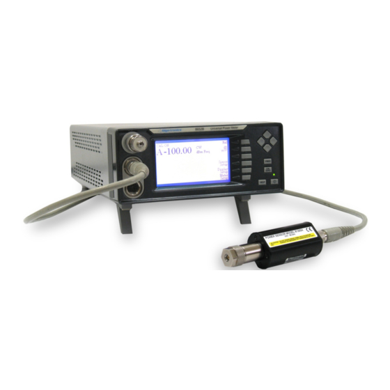
Giga-tronics 8650B Series Operation Manual (267 pages)
Universal Power Meters
Brand:
Giga-tronics
| Category:
Measuring Instruments
| Size: 8 MB
Table of Contents
Table of Contents
8
Chapter 1 Introduction
19
General Information
19
Features
19
Environmental Standards
20
Power Requirements
20
Items Furnished
20
Items Required
20
Cooling
20
Cleaning
20
Receiving Inspection
21
Reshipment Preparation
21
Installation
22
Safety Precautions
22
Power
23
Power Sensor Precautions
23
Figure 1-1: Fuse Holder
23
Interface (Rear Panel)
24
Line Voltage Selection & Fuse
24
Inputs/Outputs
24
Remote Interface
24
Figure 1-2: Series 8650B Rear Panel
24
Table 1-1: Series 8650B Rear Panel I/O Connectors
24
Specifications
25
Power Meter
25
Accuracy
26
Measurement Rates
29
Table 1-2: Measurement Rates
29
Remote Operation
30
GPIB Fast Buffered Mode Controls
30
Inputs/Outputs
30
General Specifications
31
Options
31
Power Sensors
31
Chapter 2 Front Panel Operation
33
Introduction
33
Front Panel Description
33
Figure 2-1:8652B Front Panel Layout
33
Front Panel Layout Descriptions
34
Front Panel Applications
36
Figure 2-2: Main Menu
36
Meter Setup
37
Calibrator
37
Config
38
Figure 2-3: Power Meter Configuration Display
38
Figure 2-4: Strip Chart Illustration
40
Figure 2-5: External Gating Illustration
42
Figure 2-6: External Triggering Illustration
43
Figure 2-7: Burst Edge Configuration Illustration
44
Figure 2-8: Histogram Illustration
45
Figure 2-9: CDF Curve Illustration
46
Figure 2-10: CCDF Curve Illustration
46
Sto/Rcl
47
Service
47
Display Setup
48
Figure 2-11: Configuration Display Menu
48
Figure 2-12: Data Line Configuration Menu
49
Line Configuration
49
More Options
51
Relative Mode (Rel)
51
Sensor Setup
52
Averaging
52
Figure 2-13: Sensor Setup Menu
52
Offset
53
Config
53
Measurement Guide
55
Using the Power Sweep Calibrator
55
807XXA Sensor Operation
55
Sensor Calibration & Zeroing
56
Calibration & Zeroing
56
Figure 2-14: Setup for Sensor Calibration
56
Zeroing Only
57
Calibration & Zeroing (High Power Sensors with Removable Attenuators)
57
Low Level Performance Check
58
Measuring Source Output Power
59
Using the Peaking Meter
59
Figure 2-15: Peaking Meter
59
High Power Level Measurements
60
Modulated Measurement Modes
60
MAP Mode
60
PAP Mode
61
BAP Mode
61
Figure 2-16: Burst Measurement
61
Measurement Collection Modes
63
CW Mode
63
PEAK Mode (80350A Peak Power Sensor)
63
Figure 2-17: Delay & Delay Offsets
64
Mode Restrictions
65
When to Use CW, MAP & BAP
65
Multi-Tone Tests
65
Peak Hold
67
Figure 2-18: Peak Hold
67
Crest Factor
68
Figure 2-19: Crest Factor
68
Burst Signal Measurements
70
Burst Start Exclude, Burst End Exclude
71
Figure 2-20: Burst Start Exclude & Burst End Exclude
71
Burst Dropout
72
Figure 2-21: Burst Dropout
72
Optimizing Measurement Speed
73
Peak Power Measurements
74
Measuring an Attenuator (Single Channel Method)
74
Improving Accuracy
75
Performance Verification
76
Sources of Error
77
Chapter 3 Remote Operation
79
Introduction
79
Sending Commands to the 8650B over GPIB
79
Table 3-1: Implemented IEEE Standards
79
Clear Device over GPIB
80
Clear Interface over GPIB
80
Local & Remote Control over GPIB
80
Sensor Selection & Calibration
80
Polling over GPIB
81
Parallel Polling over GPIB
81
Serial Polling over GPIB
81
Data Output Formats
82
Power-On Default Conditions
82
Remote Connection Configuration
83
Gpib
83
Lan
83
Usb
83
SCPI Command Interface
84
Sensor Calibration & Zeroing
84
Sensor & Channel Configuration
84
Figure 3-1: SCPI Subsystem Model
84
Measurement Triggering
85
Memory Functions
85
IEEE 488.2 Required Commands
85
Table 3-2: IEEE Required Command Codes
85
Calculate Subsystem Commands
86
Figure 3-2: Calculate Subsystem Commands
86
Figure 3-3: Additional Calculate Subsystem Commands (Modulation Sensors)
87
Sense Subsystem Commands
88
Figure 3-4: Sense Subsystem Command Tree
88
Trigger Subsystem Commands
90
Figure 3-5: Trigger Subsystem Command Tree
90
Figure 3-6: Sense Subsystem Command Tree for Configuring Modulation Sensors
91
Figure 3-7: Sense Subsystem Command Tree for Configuring Modulation Sensor Gate Settings
91
SCPI Command Syntax
92
Commands in Brackets
92
Programmer Selective Parameters
92
Italics in Syntax Descriptions
92
Query Format
92
Linking Command Strings
92
Measurement Data Output Format
92
Table 3-3: SCPI Command Syntax
93
Sensor Calibration & Zeroing
97
Sensor Calibration
97
Sensor Zero
98
Sensor Configuration Commands
99
Sensor Gate Commands
101
Reading Power Measurements
103
Special Errors
104
Instrument Triggering
105
Figure 3-8: Triger Sub-System Command Tree
105
Arming the Triggering Cycle
108
Channel Configuration
109
Cal Factor Correction
112
Cal Factor Error Control
113
High Speed Measurements
114
Operating Mode Control
114
Triggering Notes
116
Measurement Level Notes
116
Peak Power Sensor Triggering
117
Averaging
119
Relative or Referenced Measurements
120
Error Control
120
Offsets
121
Communication Configurations
122
Status Monitoring & Service Request Generation
123
Figure 3-9: 8650B SCPI Status Reporting Structure
123
Status Byte Register
124
Table 3-4: SCPI Status Byte Register
124
Event Status Register
126
Table 3-5: SCPI Event Status Register
126
Operation Status Register
128
Table 3-6: SCPI Operation Status Register
128
Clear Status
130
Operation Complete
130
Min/Max Configuration & Monitoring
131
Limit Line Configuration & Monitoring
132
Analog Output
134
Saving & Recalling Configurations
136
Halting Operation
137
Language Configuration
137
Preset Configuration
138
Table 3-7: Reset & Power on Default Commands (W/ CW Power Sensor Initialized)
139
Identification Commands
140
Calibrator Controls
141
Sensor EEPROM Commands
141
Self-Test
142
Error Messages
142
Table 3-8: SCPI Standard Error Messages
142
Table 3-9: Device Specific Error Messages
143
IEEE 488.2 Interface Command Codes
145
Command Syntax
145
Function Codes
145
Prefixes
145
Variables
145
Suffixes
146
Separators
146
Command Format Illustrations
146
8650B Command Code Set
147
Table 3-10: 8650B IEEE 488.2 Command Set
147
8540C Emulation Command Code Set
150
Table 3-11: 8540C Emulation Command Set
150
HP436 Emulation Command Code Set
153
Table 3-12: HP436 Emulation Command Set
153
HP437 Emulation Command Code Set
154
Table 3-13: HP437 Emulation Command Set
154
HP438 Emulation Command Code Set
156
Table 3-14: HP438 Emulation Command Set
156
Analog Output
158
Enabling & Disabling the Output
158
Setting Options for the Output
158
Averaging
159
Auto Averaging
159
Activating the Auto Filter Mode
159
Setting the Measurement Settling Target
159
Table 3-15: Measurement Setting Target Default Values
159
Freezing the Present Averaging Number
160
Manual Averaging
161
Table 3-16: Number Averaging
161
Cal Factors
162
Calibration
163
Calibration Routine
163
Calibrator Source
164
Calibrator Test
165
Channel Designation
166
Crest Factor
167
Enabling the Crest Factor Feature
167
Reading the Crest Factor Value
167
Display Control
169
Display Testing
169
Displaying Messages
169
Duty Cycle Commands
170
Activating or Deactivating a Duty Cycle
170
Specifying a Duty Cycle
170
Reading Duty Cycle Status
170
Time Gating Measurement
171
Description
171
External Gating Mode
171
External Trigger Mode
171
Internal Burst Edge Detection
171
Time Gating Mode
172
Gate a or B
172
OFF or GATE or TRIGGER or EDGE
172
INVERT or NONINVERT
173
DELAY D
174
DURATION G
174
HOLDOFF H
175
Error Codes
175
Eeprom
176
EEPROM Cal Factors
176
Frequency
177
Instrument Identification
178
Identification Strings
178
Learn Modes
179
Learn Mode #1
180
Requesting the String
180
Sending the String
180
Table 3-17: Learn Mode #1 Output Format
180
Learn Mode #2
181
Requesting the String
181
Sending the String
181
Limits
182
Setting Limits
182
Activating Limits
182
Measuring with Limits
183
Measurement Collection Modes (Standard)
184
Measurement Triggering
184
Trigger Hold (TR0)
184
Trigger Immediate (TR1)
184
Trigger Immediate with Full Averaging (TR2)
184
Free Run (TR3)
184
Group Execute Trigger
185
Group Trigger Hold (GT0)
185
Group Trigger Immediate (GT1)
185
Group Trigger Immediate with Full Averaging (GT2)
185
Measurement Collection Modes (GPIB-Fast)
186
General
186
Sensor Measurements Supported
186
Averaging
186
Disabled Features
186
Measurement Changes
186
Warning Regarding Interruption & Reconfiguration
187
GPIB-Fast Mode Setup
187
Data Output Formats for GPIB-Fast Modes
188
For the Swift Free-Run Mode
188
For the Swift Triggered & Fast Buffered Modes
188
For the Fast Modulated Mode
188
Fast Buffered Mode
189
Fast Buffered Mode Notes
190
Swift Mode
191
Swift Mode Notes
191
Example Programs
192
Fast Modulated Mode
193
Fast Modulated Mode Notes
193
Measurement Mode Commands
194
CW Mode
194
MAP Mode
194
PAP Mode
195
BAP Mode
195
Peak Mode
195
Measurement Mode Query
196
Advanced Features
197
Burst Start Exclude
197
Burst End Exclude
197
Burst Dropout Tolerance
198
Min/Max Power Value
198
Enabling the Min/Max Feature
198
Reading the Min/Max Values
199
Offset Commands
199
Enabling/Disabling an Offset
200
Setting an Offset Value
200
Measured Offset Entry
201
Peak Hold
202
Enabling the Peak Hold Feature
202
Reading the Peak Hold Value
202
Peak Power Sensor Commands
204
Series 80350A Peak Sensors
204
Reading Values
205
Preset
206
Table 3-18: Preset (Default) Conditions
206
Relative Measurements
207
Resolution
207
Sensor Selection
208
Status Monitoring
209
Figure 3-10: 8650B IEEE 488.2 Status Reporting Structure
209
Status Byte Register
210
Table 3-19: IEEE 488.2 Status Byte Register
210
Event Status Register
212
Table 3-20: IEEE 488.2 Event Status Register
212
Status Message
214
Table 3-21: Measurement Error Code Returned in Position AA
215
Table 3-22: Entry Error Code Returned in Position Aa
216
Table 3-23: Other Codes in the Status Message
217
Setup
218
Query a Stored Setup
218
Store a Setup
218
Store & Recall
219
Saving a Configuration
219
Retrieving a Configuration
219
Units
220
Vprop
220
PROPF Feature
220
Enabling & Disabling
220
Configuring
221
Propf
221
Histograms, CDF & CCDF
223
Setting Histogram Mode Intervals
223
Histogram Range
223
Enabling & Disabling Histograms HIST
223
Histogram Query
224
Strip Chart
225
Strip Pause/Resume
225
Strip Chart Query
225
Statistics
226
Statistics Enable/Disable
226
Statistics Query
226
Scpi
226
Chapter 4 Performance Verification
227
Introduction
227
Equipment Required
227
Table 4-1: Performance Verification - Required Equipment List
227
Calibrator Verification Procedure
228
Calibrator Output Power Reference Level
228
Procedure
228
Figure 4-1: Calibrator Output Test Setup
228
Calibrator Frequency Check
230
Performance Verification Tests
230
Equipment Required
230
Instrument Plus Power Sensor Linearity
231
Test Description
231
Figure 4-2:Power Linearity Test Setup
231
Setup Parameters
232
Test Procedure
232
GPIB Port Check
233
Appendixa Typical Applications Programs
237
Introduction
237
Continuous Data Reading
237
Remote Calibration of a Sensor
237
Speed Tests: Normal & Swift
238
Swift Demo 1: FREERUN
240
Swift Demo 2: GET
241
Fast Buffered Demo: POST GET
242
Fast Buffered Demo: POST TTL
243
Appendixb Power Sensors
245
Introduction
245
Power Sensor Selection
245
Power Sensor Selection Charts
246
Modulated Sensor Specifications
252
80401A BAP Mode Limitations
253
80601A BAP Mode Limitations
254
80701A BAP Mode Limitations
255
Directional Bridges
256
Advertisement
Advertisement
Related Products
Giga-tronics 8003
Giga-tronics 8501A
Giga-tronics 8502A
Giga-tronics 8650A Series
Giga-tronics 80350A
Giga-tronics 80353A
Giga-tronics 80354A
Giga-tronics 80355A
Giga-tronics 80351A
Giga-tronics 80352A
Giga-tronics Categories
Multiplexer
Amplifier
Switch
Measuring Instruments
Synthesizer
More Giga-tronics Manuals
Login
Sign In
OR
Sign in with Facebook
Sign in with Google
Upload manual
Upload from disk
Upload from URL