Table of Contents
Advertisement
Quick Links
ISO 9001
..................................................................................................................................... Certified Process
Registrar: BSI, Certification No. FM 34226 ❖ Registered 04 June 1996 ❖ Amended 01 March 2000
Giga-tronics Incorporated ❖ 4650 Norris Canyon Road ❖ San Ramon, California 94583
925.328.4650 or 800.726.4442 ❖ 925.328.4700 (Fax) ❖ 800.444.2878 (Customer Service) ❖ 925.328.4702 (CS Fax)
www.gigatronics.com
8003 Precision Scalar Analyzer
P/N:
Revision:
Print Date:
June 2001
Operation Manual
8003
20791
C
Advertisement
Table of Contents

Related Manuals for Giga-tronics 8003


Summary of Contents for Giga-tronics 8003
- Page 1 Registrar: BSI, Certification No. FM 34226 ❖ Registered 04 June 1996 ❖ Amended 01 March 2000 Giga-tronics Incorporated ❖ 4650 Norris Canyon Road ❖ San Ramon, California 94583 925.328.4650 or 800.726.4442 ❖ 925.328.4700 (Fax) ❖ 800.444.2878 (Customer Service) ❖ 925.328.4702 (CS Fax)
- Page 2 No statement, representing, agreement, or understanding, oral or written, made by an agent, distributor, representative, or employee of Giga-tronics, which is not contained in the foregoing Warranty will be binding upon Giga-tronics, unless made in writing and executed by an authorized Giga-tronics employee. Under no circumstances shall Giga-tronics be liable for any direct, indirect, special, incidental, or consequential damages, expenses, losses, or delays (including loss of profit) based on contract, tort, or any other legal theory.
- Page 4 Password protection can be user activated to prevent unauthorized changes in the Cal Factor and Calibrator data stored in the EEPROMs in the 8003 and sensors used with the instrument. It is strongly recommended that this password protection be implemented immediately to prevent any problems that could arise due to accidental or unintentional changes to the calibration data stored in the EEPROMs.
-
Page 5: Table Of Contents
Contents About This Manual ......................ix Conventions ........................xi Record of Manual Changes .................... xiii Special Configurations ..................... xv Introduction Description....................1-1 1.1.1 Features ..................1-1 Installation ....................1-2 1.2.1 Safety Precautions ................1-2 1.2.1.1 Power Input, Fuse & Voltage Selector ......1-3 1.2.2 Line Voltage &... - Page 6 8003 Precision Scalar Analyzer Operation Introduction....................2-1 Front & Rear Panel Descriptions..............2-1 2.2.1 GPIB Address Selection ..............2-7 2.2.2 Display Description ...............2-8 Softkey Functional Description ..............2-12 2.3.1 Softkey Labels & Color Indications ..........2-12 2.3.2 Channel & Function Selection .............2-12 2.3.3 Sensors & Sensor Calibration .............2-12 2.3.4...
- Page 7 Introduction ....................3-1 IEEE Bus Interface ..................3-1 3.2.1 Connect the System Controller .............3-1 3.2.2 Set the GPIB Address ..............3-1 3.2.2.1 Programming the 8003 ..........3-2 Structured GPIB Language ................3-7 3.3.1 Common Structure ...............3-7 3.3.2 8003 GPIB Commands ..............3-7 3.3.3 Command Execution ..............3-10 3.3.3.1...
- Page 8 8003 Precision Scalar Analyzer 3.3.21 CW Power Measurement Command Structure ......3-36 3.3.22 Temperature & Low Level Offset Update Structure .....3-49 3.3.23 Print Definition Command Structure ...........3-49 3.3.24 Readout Display Definition Command Structure ......3-50 3.3.25 Sensor Definition Command Structure ........3-51 3.3.26 Sensor Short/Open Calibration Command Structure ....3-53...
- Page 9 Sensor Installation ................ B-3 B.3.2 Bridge Installation ................. B-3 B.3.3 Sweeper Installation ..............B-4 B.3.3.1 8003 to Sweeper BNC Connections ......B-4 B.3.3.2 GPIB Interconnect Cable Connections ......B-5 Printer Installation ..................B-6 B.4.1 PaintJet Color GPIB Cable Interconnections ........B-7 B.4.2...
- Page 10 Figure 2-51: Sensor Calibration Screen..............2-95 Figure 2-52: Sensor ID Table ..................2-96 Figure 2-53: Sensor CAL Factor Table..............2-96 Figure 2-54: 8003 Swept Power Measurements with CAL Factor Correction..2-97 Figure 2-55: CW Readings (All 3 Sensor Inputs Plus Ratio)........2-98 Manual 20791, Rev. C, June 2001...
- Page 11 Preface Figure 2-56: 3 Different Methods (CAL Factor Correction Plus Sensor Offsets) ..2-99 Figure 2-57: Averaging Used to Reduce Noise ............2-100 Figure 2-58: Reference Level & Corresponding Relative Reading......2-101 Figure 2-59: Menus & Typical Display (Power Sweep Measurements) ....2-104 Figure 3-1: Location of GPIB/System Connection (Rear Panel).........3-1 Figure 3-2: GPIB Commands (Front) ...............3-8...
- Page 12 Test Equipment Required..............4-2 Table A-1: Power Sensor Selection Guide ............A-2 Table A-2: Power Sensor Cal Uncertainties ............A-3 Table A-3: Directional Bridge Selection Guide ............A-4 Table B-1: 8003 Default Settings ................. B-1 viii Manual 20791, Rev. C, June 2001...
-
Page 13: About This Manual
Purpose Interface Bus (GPIB). All programming codes are presented in this chapter with various applications to aid you in understanding the operation. 4 – Performance Test & Calibration: This chapter provides the procedures to verify the performance of the 8003 Precision Scalar Analyzer. Appendices... - Page 14 8003 Precision Scalar Analyzer Manual 20791, Rev. C, June 2001...
-
Page 15: Conventions
Conventions The following conventions are used in this product manual. Additional conventions not included here will be defined at the time of usage. Warning WARNING WARNING The WARNING statement is encased in gray and centered in the page. This calls attention to a situation, or an operating or maintenance procedure, or practice, which if not strictly corrected or observed, could result in injury or death of personnel. - Page 16 8003 Precision Scalar Analyzer Manual 20791, Rev. C, June 2001...
-
Page 17: Record Of Manual Changes
Record of Manual Changes This table is provided for your convenience to maintain a permanent record of manual change data. Corrected replacement pages will be issued as Technical Publication Change Instructions, and will be inserted at the front of the binder. Remove the corresponding old pages, insert the new pages, and record the changes here. - Page 18 8003 Precision Scalar Analyzer Manual 20791, Rev. C, June 2001...
-
Page 19: Special Configurations
Special Configurations When the accompanying product has been configured for user-specific application(s), supplemental pages will be inserted at the front of the manual binder. Remove the indicated page(s) and replace it (them) with the furnished Special Configuration supplemental page(s). Manual 20791, Rev. C, June 2001... - Page 20 8003 Precision Scalar Analyzer Manual 20791, Rev. C, June 2001...
-
Page 21: Introduction
A front panel calibrator linearizes sensors and bridges to ± 0.04 dB linearity, and provides an absolute power accuracy of ± 0.7% at 1 mW. In essence, the 8003 can be used as an accurate 3-channel power meter. -
Page 22: Installation
1.2.1 Safety Precautions This 8003 has a 3-wire power cord with a 3-terminal polarized plug for connection to the power source and safety-ground. The ground (or safety ground) is connected directly to the chassis. WARNING If a 3-to-2 wire adapter is used, connect the ground lead from the adapter to earth ground. -
Page 23: Power Input, Fuse & Voltage Selector
Introduction The 8003 is designed for international use with source voltages of 100, 120, 220, or 240 Vac, ±10% at 48 to 440 Hz. The 8003 uses an internationally approved connector that includes voltage selection, fuse, and filter for RFI protection. -
Page 24: Power Requirements
220/240 Vac, ± 10%, 50, 60 or 400 Hz 1.5 AMP CAUTION Verify that the voltage setting and line fuse in the 8003 match the ac power source at your facility before connecting the line power cord. The unit is set at the factory for operation at the normal supply voltage for the country in which it is sold. -
Page 25: Standard Voltage Selector & Fuse Holder
In addition to options and/or accessories specifically ordered, items furnished with the instrument are: • 1 ea. - Power Cord • 1 ea. - Model 8003 Network Analyzer & CW Power Meter • 1 ea. - Operation Manual (P/N 20791) •... -
Page 26: Items Required
8003 Precision Scalar Analyzer 1.2.7 Items Required The 8003 requires an external power sensor; see Appendix A for Power Sensor Specifications. 1.2.8 Tools & Test Equipment No special tools are required to operate the 8003. 1.2.9 Cooling No cooling is required if the instrument is operated within its specified operating temperature range (0 to 50°C). -
Page 27: Specifications
The following are the specifications for the 8003. System Frequency Range: 10 MHz to 40 GHz in coax using Giga-tronics 803XXA Series power sensors and 80500 Series bridges and an appropriate sweeper (see the signal sources in Appendix A) Power Range:... -
Page 28: Cursors & Markers
Changes the Ref Level to the level at the cursor. Markers: Displays up to 10 markers generated by the 8003. The cursor can be moved directly to any marker or sequentially through the markers. Manual 20791, Rev. C, June 2001... -
Page 29: Accuracy
Introduction 1.3.2 Accuracy 1.3.2.1 Transmission Loss or Gain Measurements Transmission loss or gain measurements are made relative to a 0 dB reference point established during calibration. Therefore, frequency response errors of the source, sensors, and signal splitting device are removed. The remaining elements of uncertainty are instrument linearity and zero set uncertainty, see Figure 1-3, and mismatch error. -
Page 30: Reflection Measurements
8003 Precision Scalar Analyzer 1.3.2.2 Reflection Measurements When measuring devices with high return loss (>10 dB), reflection accuracy is typically dominated by the effective system directivity, instrument linearity errors, and noise uncertainty. With low return loss devices (<10 dB), reflection accuracy is typically dominated by source match. Calibration with an open and short effectively removes uncertainties due to frequency response of the source, sensors, and signal splitting device. -
Page 31: Absolute Power Measurement Accuracy
Introduction 1.3.2.3 Absolute Power Measurement Accuracy The absolute power measurement accuracy is determined by a number of factors including calibrator accuracy, zero set error, noise, sensor calibration factor error, and the mismatch uncertainty between the sensor and the device under test. Calibrator Provides a 50 MHz calibration signal at 51 precise levels from +20 dBm to -30 dBm to dynamically linearize the sensors. - Page 32 8003 Precision Scalar Analyzer Zeroing Accuracy (CW Mode, Averaging Factor = 32): Zero Set: ±50 pW Zero Drift: Typically ±200 pW in 1 hour at constant temperature after a 24-hour warmup. (Swept Mode, Averaging Factor = 32): Zero Set: ±50 pW (AC Detection) ±800 pW (DC Detection)
-
Page 33: Gpib Interface
Introduction GPIB Interface Interface Operates according to IEEE 488.1 and IEC-625 interface standards. A private line GPIB is used to connect the analyzer to firmware supported sweepers. Programmable Functions All front panel functions except power on/off are programmable. Interrupts SRQs are generated for the following conditions: •... -
Page 34: Rear Panel Inputs & Outputs
GPIB Connectors System GPIB Used to connect the 8003 to a GPIB controller. Private GPIB Used to connects the 8003 to a signal source and plotter. RS-232 Port Serial Communication Interface for driving an HP Laserjet printer. 1-14 Manual 20791, Rev. C, June 2001... -
Page 35: Signal Sources
• Wiltron 6700B Synthesized Sweep Generators 1.6.2 Operator Integrated The 8003 is compatible with any signal source that meets the following requirements: Horizontal Ramp: Provides a 0 to +10 V nominal ramp signal. Blanking Signal: (Optional) Provides a TTL level during retrace and bandswitching. - Page 36 8003 Precision Scalar Analyzer 1-16 Manual 20791, Rev. C, June 2001...
-
Page 37: Introduction
Operation Introduction This chapter describes how to operate the 8003 Precision Scalar Analyzer from its front and rear panels. Refer to Chapter 3 for instructions on how to operate the instrument from a remote host computer over the General Purpose Interface Bus (GPIB) or an RS-232 serial connection. Refer to Chapter 1 for instructions on how to install and interface the instrument before operating it for the first time. -
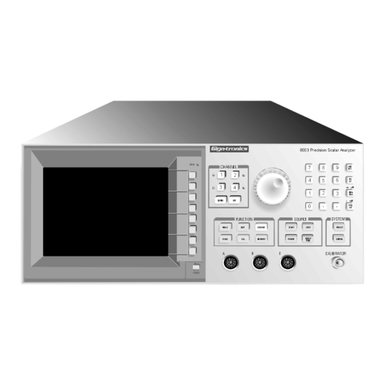
Page 38: Figure 2-1: 8003 Front & Rear Panel Components
8003 Precision Scalar Analyzer Figure 2-1: 8003 Front & Rear Panel Components Manual 20791, Rev. C, June 2001... - Page 39 EEPROM. See Section 2.8.1 for more information on calibration proce- dures. SYSTEM Control Keypad key of this keypad configures the 8003 and any other devices that might be [CONFIG] interconnected on the 8003 private bus (see Section 2.7).
- Page 40 Power On/Off Switch This is a push-push switch to control the ac power to the 8003. The ON condition is indicated by illumination of one or more of the Channel Indicator LEDs.
- Page 41 The Input 1 TTL Levels connection provides the necessary synchronization to an internal log circuit of the 8003 when used with certain sweepers. For example, if a synthesized sweeper is being used, the TTL signal would tell the 8003 that the sweeper is locked, leveled, and that the signal was useful.
- Page 42 This is a standard serial port to drive printers or plotters to generate hardcopy of a screen or data information dump. GPIB/System This connection interfaces the 8003 to a remote controller when the instrument is to be remotely operated over the GPIB. Lithium Battery The 3.5 V lithium back-up battery powers the non-volatile memory when the instrument is turned off.
-
Page 43: Gpib Address Selection
2. The menu that next appears will have a softkey labeled [GPIB DEVICES]. Press this key. 3. The display will then show the 8003 address and prompt to change the address. Enter any desired address (0 through 30) that is not currently being used for another device on the bus. The default address for the instrument is 4. -
Page 44: Display Description
8003 Precision Scalar Analyzer 2.2.2 Display Description Channel Summary Area Channel Titles CH1: SW C CRSR -0.19 dB CH2: C/A-PC CRSR -0.14 dB CURSOR 0.1 dB/ -0.00 dB 0.1 dB/ 0.00 dB FREQ CURSOR Active Entry Area / CRSR -0.14... - Page 45 Operation Start, Center, CW Frequency Shows the frequency mode currently in use (STRT, CNTR, or CW), and the frequency selected to be used with that mode. Reference Position Indication This area shows the selected frequency reference point for each channel being displayed (channels 1 and 2 in Figure 2-2).
-
Page 46: Figure 2-3: Typical Channel Summary Indications
8003 Precision Scalar Analyzer Figure 2-3 shows some of the most commonly used parameters and their locations in the Summary Area. The text following the figure gives a brief description of the parameters and, where applicable, refers you to sections of the manual where complete definitions can be found. - Page 47 Operation Reference Level Indicates the value set for the Reference Position(s) of the trace displays for each displayed channel, as shown in Figure 2-3. Minus Trace 0 Shows that a trace stored in memory (location 0 through 9) is being subtracted from the measurement. Smoothing, Hold and Averaging Display of any or all of the S, H, and/or A indications means that the displayed Smoothing, Hold, and/ or Averaging function is active in the measurement.
-
Page 48: Softkey Functional Description
This is a detailed description of the functions for setting up and preparing to take measurements with the 8003. The 8003 is addressed and controlled by four groups of specific functional keys, eight softkeys for accessing menu options, a data entry key group, and a spin knob located on the front panel. -
Page 49: Absolute Power & Swept Capabilities
The path calibrations will be performed and stored by sensor, not by channel. The 8003 allows the definition, by channel, of whether or not to use path calibrations. If it is specified that path calibrations should be used on a channel, then the measurement of each sensor being used by the channel is ratio’ed with its path calibration. -
Page 50: Trace Memory
8003 Precision Scalar Analyzer When path calibration is used, the 8003 does not apply Cal Factors to the readings. Cal Factors are only useful for absolute power measurements. Any Cal Factor correction would be canceled when making relative measurements. To make the path calibration over wide frequency ranges useful, the 8003 memorizes a very large number of data points (up to 4096) during a path calibration. -
Page 51: Channel Controls
Operation CHANNEL Controls The 8003 has four channels. The measurements to be made on each channel, including the sensor(s) to make the measurement, can be independently specified. Any number of channels, 1 through 4, can be on at the same time. - Page 52 8003 Precision Scalar Analyzer [ DIFF ] Menu C1: Accesses the differential measurement capability of the 8003. This feature is usable only for channels in the CW mode, and would cause all softkey labels to revert to dim, dark blue if the routine were changed from the CW to the swept mode at any point while the DIFF softkey menus were in use.
-
Page 53: Figure 2-5: Channel Control Menus Access W/ Define Key
Operation SINGLE DEFINE SENSOR A / B RATIO B / A A / C DIFF C / A B / C * NF C / B RETURN RETURN CW / RETURN SWEPT RETURN DEFINE DEFINE DEFINE BIAS RETURN DEFINE C1-3 C1-1 VOLTAGE C1-2... -
Page 54: Function Controls
8003 Precision Scalar Analyzer FUNCTION Controls The major functions of the 8003 are controlled by the six FUNCTION keys. These keys access the measurement functions of the instrument and change measurement parameters when required. Each of the primary functions and the menus and sub-menus accessible by these six keys are described in this section. - Page 55 Operation [ ABS PWR PATHCAL ] Menu F1: Toggles between absolute power measurements using Cal Factors, and relative measure- ments that are being ratio’ed with a stored path cal. When the Absolute Power measurement mode is active (ABSPWR shown on the menu in light blue), the instrument applies a Cal Factor to each reading.
- Page 56 8003 Precision Scalar Analyzer If a trace is memorized as trace n, whatever trace was previously memorized as trace n will be overwritten and cannot be retrieved. However, the title of the memorized trace is not affected by the memorization of a new trace.
- Page 57 Operation [ CW OPTION ] Menu F1: Accesses certain measurement functions which can be taken only when in the CW mode. [ REL ON/OFF ] Menu F1-2: Accesses the CW Relative measurement mode. When this softkey is pressed to initiate the relative mode, the CW measurement on the entry channel is memorized and all future measurements on that channel are made relative to the memorized measurement.
-
Page 58: Scale Key
During every update of the channel’s trace, the 8003 will internally autoscale the channel. The scaling that results from this autoscale will be compared with both the channel current scaling and the results from recent autoscales. - Page 59 Operation [ REF LEVEL ] First Level Menu F3: Sets the power level corresponding to the reference line being used for the entry channel main trace. The reference level is the power level around which the channel main trace is scaled. As scaling changes, the points on the reference line which intersect the power trace will not change.
-
Page 60: Display Key
Smoothing reduces ripple in the trace. Smoothing is not the best choice for reducing noise. In the presence of noisy signals, averaging should be used. When both smoothing and averaging are used, the 8003 first averages consecutive unsmoothed traces then smooths each resulting averaged trace. - Page 61 Operation [ SMOOTH APERT ] Menu F3-2: Selects the smoothing aperture parameter when in the smoothing mode. The smoothing aperture is the percentage of the channel trace to be averaged for each data point. The smoothing aperture can be either selected with the spin knob or entered through the numeric keypad.
-
Page 62: Figure 2-7: Function Menus Accessed W/ Display Key
8003 Precision Scalar Analyzer AVG N DISPLAY SMOOTH HOLD ON / OFF APERT ON / OFF SMOOTH- PLOT ALL SMOOTH PLOT & ON / OFF PRINT PLOT 4 LIMIT PRINT RETURN LINES LMT LNS RETURN PLOT ON /OFF POINT CUSTOM... -
Page 63: Figure 2-8: Plot All Function Hardcopy Printout (Typical)
The [PLOT ALL] softkey causes all of these elements to be printed on the hardcopy in a stan- dard (8-1/2 x 11") format. If the 8003 has trace data available on all four channels, the data from each of channel can be printed in a different color on a 4 (or more) pen plotter. -
Page 64: Figure 2-9: Plot 4 Function Hardcopy Printout
8003 Precision Scalar Analyzer [ PLOT 4 ] Menu F3-3: Initiates the printing of separate plots for each of the four channels. Pressing [PLOT 4] brings up a sub-menu (F3-4) that allows you to select into which of the four quad- rants of the hard copy each channel is to be positioned. -
Page 65: Figure 2-10: Sc P1P2 Function Screen Hardcopy Printout
Operation [ PLOT CUSTOM ] Menu F3-3: Activates a printout containing the plot parameters that were selected using the [DEFINE CUSTOM] softkey. [ DEFINE CUSTOM ] Menu F3-6: The Define Custom function allows you to select specific plot parameters to be shown on the hardcopy printout. - Page 66 8003 Precision Scalar Analyzer [ ABORT PLOT ] Menu F3-3: Aborts the plotting sequence at any time. [ ED LOGO ] Menu F3-3: Accesses Menu F3-3A where you can enter your company name or logo when desired. The logo will be stored in a non-volatile RAM so it will be retained during power down.
- Page 67 Menu F3-10. The choices are a POINT LIMIT, a FLAT LIMIT, and a SLOPE LIMIT. When the softkey for the type of limit line is pressed, the 8003 will automatically assign a num- ber between 1 and 12 to the segment to be defined and position a box to the START-FREQ column in the Limit Lines Table.
- Page 68 8003 Precision Scalar Analyzer [ UNITS ] Menu F3: Selects the units (dB or W) in which the measurement on the entry channel will be dis- played. The menu will change to Menu F3-11. This key is active only in the CW mode. This is because swept mode data is always displayed in log- arithmic (dB or dBm) units.
- Page 69 Operation [ DISPLAY SETUP ] Menu F3): Define the color of the various elements of the display, which labels should be displayed, and titles for the display and the entry channel (see Figure 2-7). When the sub-menus associated with the COLOR and LABELS softkeys are accessed, the display will show the current state of the color or label of interest in light blue.
- Page 70 8003 Precision Scalar Analyzer [ FREQ LBL ON/OFF ] Menu F3-17: Toggles the frequency labels to be displayed or removed from the graph display as indicated. The frequency labels include the start, stop, cursor and cursor ∆ frequency labels which are shown at the bottom of the graphic display. This can be specified at any time. How- ever, if the routine is in the data readout display mode, any changes will not be apparent until the graph display mode is entered.
- Page 71 Operation When the title is at its maximum length, the cursor will remain at the last character position and any new characters input will simply replace the last character in the string. When the title has been completed, the routine is returned to menu F3-12 by pressing the GHZ dB or ENT OFF function key to the right of the numeric keypad.
-
Page 72: Cal Key
When the key associated with the sensor of interest is pressed, the softkey menu will go blank. The active entry area of the display will contain the message, Storing Short. If the 8003 is controlling the source, it will temporarily select a source sweep time suitable for storing the large number of data points needed (up to 4096). - Page 73 Operation [FULL BAND (A, B, or C) Y/N ] Menu F4-1: The 8003 uses adaptive normalization. That is, the start and stop frequencies can be changed within the frequency range for which the calibration was performed and the 8003 will automatically use the relevant calibration data.
- Page 74 8003 before pressing any of the softkeys shown in menu F4-4. [ CAL ALL ] Menu F4-4: Initiates the routine to calibrate all of the 8003 sensors and bridges. The instru- ment will test its sensors to try and determine which one is currently connected to the calibra- tor, and then attempt to calibrate it.
- Page 75 (40 dBm). At very low levels (60 dBm), zeroing should be done every few minutes. [ ZERO ALL ] and [SENSOR (A, B, and C)] Menu F4-5: Causes the 8003 to attempt to zero all of its calibrated sensors. Pressing SENSOR A, SENSOR B, or SENSOR C will zero one sensor at a time.
-
Page 76: Cursor Key
When a marker is set at a particular frequency, the marker will be visible on all channel traces. The 10 markers available in the 8003 are set by moving the cursor to the desired frequency, and then by defining the marker to be at that frequency. - Page 77 Operation [CURSOR ∆ ON/OFF] Menu F5: Toggles the cursor ∆ on or off. The state that the cursor ∆ capability is currently in (On or Off) is displayed in light blue. When the cursor ∆ is turned on, the regular cursor capability of the instrument will also be turned on if it is off.
-
Page 78: Figure 2-12: Function Menus Accessed With The Cursor & Memory Keys
8003 Precision Scalar Analyzer CURSOR CURSOR FREQ CURSOR ON / OFF ∆ CURSOR SEARCH ON / OFF VALUE SEARCH SEARCH LEFT ∆ CURSOR MRKR N SEARCH DEFINE RIGHT MRKR N DEFINE MRKR N BAND- CURSOR WIDTH FREQ ∆ CURSOR MRKR N... - Page 79 [ SEARCH LEFT ] [ SEARCH RIGHT ] Menu F5-1: Initiates the search function. If the cursor ∆ is active, the 8003 will search in the indicated direction (left or right) from the current position of the cursor. It will look for the level that is equal to the search value in relation to the level at the cursor ∆...
- Page 80 8003 Precision Scalar Analyzer As the preceding description implies, this function requires two markers. Therefore, if the bandwidth function is successful, the cursor ∆ capability of the instrument will be turned on if it was off. When this function is used, the cursor ∆ will always be positioned to mark the left bandwidth marker on the display.
- Page 81 Operation [ DEFINE MRKR N ] First Level Menu F5: Defines a marker at the cursor frequency. This softkey is also used to turn markers on and off and to clear markers. When this softkey is pressed, the cursor capability will be turned on if it is off.
- Page 82 8003 Precision Scalar Analyzer [ CLEAR MRKR N ] Menu F5-2: Clears a defined marker. When a marker is cleared it is turned off, its defined fre- quency is erased, and it becomes an undefined marker. When this softkey is pressed, the entry area of the display will present a prompt to enter the number of the marker that it is desired to clear.
-
Page 83: Memory Key
Operation 2.5.6 MEMORY Key [MEMORY] The FUNCTION key accesses the Store and Recall of instrument setups. These setups [MEMORY] are stored in non-volatile memory and will not be disturbed upon power down. When the MEMORY key is pressed, the entry area of the display will present a prompt to enter the number of the stored setup to be recalled. - Page 84 Display menu is used, and it is then desired to display a numbered setup. When the number of the setup to be displayed is entered, the 8003 will stop taking and display- ing measurements. The measurement area of the display will instead show all of the requested setup’s parameters.
- Page 85 Clear menu has been used, and it is then desired to clear a num- bered setup. When the number of the setup to be cleared is entered, the 8003 will clear the stored setup and indicate in the entry area of the display that it has completed this task. The number of another stored setup to be cleared can then be entered.
- Page 86 8003 Precision Scalar Analyzer When the [CLEAR ALL MEM] softkey is pressed, all of the non-volatile memory will be cleared and the instrument will be Preset. ☛ ☛ ☛ ☛ NOTE: This action cannot be reversed once accomplished. If the [ABORT CLEAR] softkey were pressed, the routine would return to the CLEAR N soft- key menu (F6-2).
-
Page 87: Source Controls
8003 to cause it to set up both itself and the source for standard scalar measurements. If it is desired to control the source from a controller other than the 8003, the 8003 can be set to turn its private bus off (see Menu SY1-10 in Figure 2-16). -
Page 88: Key Operation
Control menus. Its purpose is to enable or disable the source sweeper configuration update. The default is ON (enable). For example: If it were desired to display a range of 1 to 10 GHz on the 8003 but the sweeper output is from 2 to 5 GHz, the following procedure would be accomplished: •... -
Page 89: Stop Key
Operation the softkey (START, CENTER or CW) will be displayed in the entry area of the display. For exam- ple, if the source were in the Start/Stop mode, the START label would be in light blue. If the [CENTER] softkey were pressed, then the CENTER label would change to light blue, the START label would change to standard menu green, and the source would begin measuring in the Center/ ∆... -
Page 90: Power Key
8003 Precision Scalar Analyzer 2.6.5 POWER Key [POWER] See the description of the UPD SWP ON/OFF softkey in section 2.6.4.1. The frequency ranges of the sweeps defined by the start/stop frequencies and the center/ ∆ F frequencies are completely independent. Whenever one frequency mode (start/stop or center/ ∆ F) is changed to the other, the instrument will always revert to the frequency range last defined for the mode to which the instrument was switched. - Page 91 Operation [ POWER SWEEP ] Turns on the Power Sweep function as described in Section 2.14. The following sub-menu softkey selections will be available (as shown in Figure 2-15): [ PWR SWP ON/OFF ] Controls the enabling or disabling (toggle) of the power sweep measurement mode. [ START POWER ] Allows the entry of the desired power sweep starting power level (in dBm).
-
Page 92: Sweep Time Key
8003 Precision Scalar Analyzer 2.6.6 SWEEP TIME Key [ SWEEP TIME ] When the SWEEP TIME softkey is pressed, the entry area of the display will again show the currently defined sweep time. Note that this is the same type of data entry that is allowed when the SWEEP TIME function key is pressed. -
Page 93: System Controls
If the 8003 is commanded to automatically determine the frequency of the signal, it will use the source’s CW output frequency that was set by the 8003. If the 8003 is not con- trolling the source, the 8003 will still use the frequency set in the source control section. The speci- fication of the CW mode of frequency correction is accessed through the [SENSOR CW FREQ] softkey. -
Page 94: Figure 2-16: System Control Menus Accessed With Config Key (Part 1)
8003 Precision Scalar Analyzer CONFIG SEE CONFIG (SERVICE) MENUS SERVICE ALL AC SENSORS AC / DC ALL DC SENSORS SENSOR A CW FREQ A CW CW FREQ AC / DC FREQ SENSOR B CW CAL B CW AC / DC... -
Page 95: Figure 2-17: System Control Menus Accessed With The Config Key (Part 2)
Operation SEE CONFIG (SYSTEM) MENUS SET CAL CONFIG SENSORS SET CAL OUTPUT AC / DC SET CAL SENSORS SET TIME S / N HOUR CW FREQ DEFINE MINUTE SENSORS TEST PASSWORD GRID L / S OFFSET PATTERN SECOND CLEAR DOTS L / S PULSE PASSWORD DATE... - Page 96 80340 Series of Triggerable Pulse (Peak Power) Sensors are used with the 8003. The channel of interest is first selected and then either the Free Run, Trig’d, or Delay Trig’d mode is specified in menu SY1-9. In the Free Run mode, the RF power is sampled automatically and the sensor does not require a trigger signal.
- Page 97 SY1-10 sets the address of the printer being used in the system (default is 01). [ CAL SWP RAMP ] Menu SY1: Synchronizes the 8003 to the ramp from the sweeper. This will need to be done if the trace length on the display is less than the full 8 horizontal divisions.
- Page 98 The 8003 will also memorize the time when the DONE softkey is pressed as the new calibration time. The instrument will return to the SET CAL softkey of menu SY1-13.
- Page 99 Menu SY1-16: Terminates the display of test patterns. The routine will return to the Test Pat- tern menu (SY1-13). [ SENSOR EEPROM ] Menu SY1-13: Enters the routines necessary to either view or change the calibration data for the power sensors and/or bridges connected to the 8003. Manual 20791, Rev. C, June 2001 2-63...
- Page 100 Menu SY1-19: These softkeys directly access the first and last pages, respectively, of the cali- bration data. [ ENABLE INPUT ] Menu SY1-19: The default condition of the 8003 is for data input to be enabled. This can be defeated using [ENT/OFF]. To re-enable, use [ENABLE INPUT]. [ SET TIME ] Menu SY1-18: This softkey functions the same as [SET TIME] described on page 2-62.
- Page 101 [RETURN] to cancel. [ ENABLE INPUT ] Menu SY1-18: The default condition of the 8003 is for data input to be enabled. This can be defeated using the [ENT/OFF] key. To re-enable, use the [ENABLE INPUT] softkey.
-
Page 102: Front Panel Operation
This will prepare you for making the specific types of measurements described in succeeding sections. The discussion assumes that you are using the 8003 Precision Scalar Analyzer with a supported microwave sweeper, a Series 803XXA power sensor, and a Series 80500 return loss bridge. -
Page 103: Calibrating For Power Measurement
Operation 2.8.1 Calibrating for Power Measurement Before the 8003 analyzer can operate, the Power Sensor and Bridge must be calibrated. Connect the power sensor to the 8003 analyzer front panel connector marked . You may need to use CALIBRATOR an adapter to adapt from the sensor connector to the front panel type N(f) connector. Press Function and look at the softkey menu. -
Page 104: Calibration Intervals
8003 Precision Scalar Analyzer Press , where X is the correct sensor input (A, B, or C). As the sensor calibrates [ SENSOR X CAL ] you should see a display develop that looks something like Figure 2-21 when the calibration has completed. -
Page 105: Path Calibration Correction For Component Variations
Operation 2.8.2 Path Calibration Correction for Component Variations These procedures explain how to perform path calibration corrections for component variations. Connect the input port of the bridge to the RF Output connector of the sweeper. You may need an adapter to adapt the sweeper to the bridge. Configure the analyzer for your measurement. -
Page 106: Frequency Response Correction
8003 Precision Scalar Analyzer sweeper turns on. Press and enter the desired sweep time on the numeric entry pad, [SWEEP TIME] and press the appropriate units key (ms or s) (0.5 second is recommended initially). SCALE CH1 : SW A FACTOR 0.1 Db /... -
Page 107: Figure 2-24: Thru Path Calibration Menu
Operation To do a path calibration, press Function then press which brings up the F4-2 menu in [CAL] [ THRU ] Figure 2-24. STORE THRU A STORE THRU B STORE THRU C A FULL BND Y/N B FULL BND Y/N C FULL BND Y/N RETURN... -
Page 108: Figure 2-25: Calibrated Path Display
8003 Precision Scalar Analyzer Press . The analyzer will display the message [ STORE THRU A ] PREPARING SOURCE FOR . When it is done, the analyzer will display . Press ‘A’ THRU ‘A’ THRU PATH CAL DONE then [REF LEVEL], and then press the digit... -
Page 109: Making A Device Measurement
Operation to the bridge test port. Connect an open to the bridge test port and press [STORE OPEN B]. When the analyzer finishes this calibration, it is ready to make fully corrected, accurate reflection measurements. CH2: SW B STORE 1.0 dB/ 0.00 dB SHORT A STORE... -
Page 110: Figure 2-27: Device Measurement Plot (Typical Display)
STOP 12.000 GHz Figure 2-27: Device Measurement Plot (Typical Display) You should now be familiar with the basic operation of the 8003 Precision Scalar Analyzer. Refer to Chapter 3 for remote operating instructions via the GPIB. CH2 : B -2.06 dB... -
Page 111: Insertion & Return Loss Measurements
Operation Insertion & Return Loss Measurements This section defines how to configure your signal splitting components to make accurate insertion and return loss measurements on a device or component. Depending on how you configure your measurement accessories, you must DEFINE a channel path and choose how you will MEASURE your device against stored calibration or trace data. -
Page 112: Using Channels
8003 Precision Scalar Analyzer CH2: C/A -PC CRSR -0.14 dB CURSOR CH1: SW C CRSR -0.19 dB 0.1 dB/ 0.00 dB 0.1 dB/ -0.00 dB FREQ CURSOR CRSR -0.14 ON/OFF 7.055 GHz ∆ CURSOR ON/OFF SEARCH CURSOR -> MRKR N... -
Page 113: Two-Sensor Insertion Loss Measurements
Operation 2.9.2 Two-Sensor Insertion Loss Measurements The basic two-sensor insertion loss measurement consists of monitoring the power incident upon the DUT, and comparing it to the power exiting the DUT. Incident power can be monitored in a variety of ways, but the two most common are to use a Power Splitter or Directional Coupler, shown in Figures 2-31 and 2-32. - Page 114 8003 Precision Scalar Analyzer In a two-sensor measurement, the power ratio of the two sensors is displayed as the measurement. After pressing the key, the [RATIO] softkey allows you to choose the proper ratio. The [DEFINE] numerator, or first sensor selected, should be the sensor monitoring the power out of the DUT. The denominator, or second sensor selected, should be the sensor measuring incident power (power into the DUT).
-
Page 115: Single-Sensor Return Loss Measurements
Operation 2.9.3 Single-Sensor Return Loss Measurements There are two types of single-sensor return loss measurements; one using a return loss bridge, and one using a directional coupler. Both types use exactly the same operating procedure. Return loss bridges are more common because of their broad frequency range and very good directivity. Figures 2-33 and 2-34 show typical examples of test setups using bridges and couplers. -
Page 116: Figure 2-34: Return Loss Test Setup Using A Directional Coupler
8003 Precision Scalar Analyzer Figure 2-34: Return Loss Test Setup Using a Directional Coupler In a single-sensor return loss measurement, the incident power is measured during path calibration and stored by the analyzer. It is then subtracted from the measured reflected power (subtracting dB’s is equivalent to ratio’ing Watts). -
Page 117: Two-Sensor Return Loss Measurements
Operation 2.9.4 Two-Sensor Return Loss Measurements In a two-sensor return loss measurement, a power splitter or directional coupler is inserted between the return loss bridge or reflection directional coupler to monitor incident power. Figure 2-35: Two Sensor Return Loss Setup Block Diagram The ratio of the reflected to incident power with the path cal subtracted then properly indicates return loss. -
Page 118: Three-Sensor Configurations
8003 Precision Scalar Analyzer 2.9.5 Three-Sensor Configurations Three-sensors typically measure both power through the device and power reflected from the device, ratio’ed with the monitored incident power level. Typically, two channels display insertion loss and return loss simultaneously. See the discussions for two channel insertion loss and two channel return loss measurements to define the channels and path cal the sensors. -
Page 119: Figure 2-37: "Golden Standard" Precision 20 Db Attenuator Measurement Using 20 Db
Operation LMT LNS CH2:SW -PC CRSR 0.11 dB ON/OFF 0.1 dB/ -T1 0.00 dB DEFINE SEGMENT STRT-FREQ UPPER LOWER STOP-FREQ UPPER LOWER SEGMENT 4.000 GHz 0.20 -0.20 8.000 GHz N CLEAR 8.000 GHz 0.25 -0.25 10.000 GHz CLR ALL SEGMENTS PLOT ENTRIES ABORT... -
Page 120: Scaling The Display
8003 Precision Scalar Analyzer 2.10 Scaling the Display One very common operation in a scalar analyzer is scaling the vertical axis. Scaling allows you to optimally position a channel trace on the screen, whether it is to see the device’s gross characteristics (such as filter skirts or amplifier out-of-band rolloff), or the fine characteristics (such as ripple in a filter or amplifier’s pass band), or to zoom in at a certain level to see how close a device makes or misses its... -
Page 121: Figure 2-40: Scale Display & Softkey Menu Typical Display
Operation All of the scaling functions of the analyzer can be found under the key. Each channel can be [SCALE] scaled independently, so the proper channel button must be pressed to make it the active entry channel before scaling. To scale a channel, press to bring up the scaling softkey menu on the display. -
Page 122: Hints On Simplified Scaling
8003 Precision Scalar Analyzer 2.10.1 Hints on Simplified Scaling The proper choice of REF POSition for the reference line can greatly simplify scaling. For device characteristics that only vary in one direction (for example, the gross characteristics of a filter, or almost any return loss trace), a convenient choice of the REF POS might be the top graticule line. -
Page 123: Cursors & Markers
2.11 Cursors & Markers Cursors and markers provide a very convenient way to read numeric values right off the trace. The 8003 Precision Scalar Analyzer can display up to one cursor, one delta-cursor, and ten markers simultaneously on all four channels). -
Page 124: Figure 2-43: Max Search Finds Minimum Return Loss Of A Filter (Passband)
8003 Precision Scalar Analyzer CH2: SW B -PC CRSR -14.61 dBm CURSOR 10 dB/ 0.00 dBm FREQ CURSOR CRSR -14.61 dBm ON/OFF -4.768 GHz ∆ CURSOR ON/OFF SEARCH CURSOR -> MRKR N DEFINE MRKR N REF -> CURSOR CURSOR STRT 2.000 GHz... -
Page 125: Searches On Frequency Selective Devices
One of the most common searches on frequency selective devices is the . This is easily -3 dB point done on the 8003 Analyzer by pressing followed by the [SEARCH] softkey. [CURSOR] Note the Cursor position in relation to the target -3 dB point on the trace. Press [SEARCH LEFT] to search to the left of the cursor for the -3 dB point. -
Page 126: Figure 2-46: -30 Db Point (High Pass Filter)
8003 Precision Scalar Analyzer CH1: SW A -PC CRSR -30.00 dB SEARCH 10.0 dB/ H REF -0.00 dB VALUE SEARCH SRCH -30.00 LEFT 6.417 GHz VALUE FOUND: TRACE HOLD SEARCH RIGHT BAND- WIDTH RETURN CURSOR STRT 5.000 GHz CRSR 6.417 GHz STOP 8.000 GHz... -
Page 127: Bandwidth Searches
Operation 2.11.4 Bandwidth Searches The 8003 Analyzer can also find the bandwidth of frequency selective devices. Press [CURSOR] followed by the [SEARCH] softkey. Then press the [BANDWIDTH] softkey. The analyzer will automatically find the maximum point in the pass band of the device, then find the -3 dB points on the right and left of the maximum, and calculate the bandwidth. -
Page 128: Cursor Delta (∆) Functions
2.11.5 Cursor Delta (∆) Functions The 8003 Analyzer can make relative level and frequency measurements using the Cursor Delta function. To make a relative measurement, first place the Cursor at the desired reference point. Then press the [CURSOR ∆ ON/OFF] softkey to toggle the Cursor Delta function on (ON should be in light blue). -
Page 129: Cursors On Multiple Channels
Operation 2.11.6 Cursors on Multiple Channels Whenever cursors are used on multiple channels, they will always be tied to the same frequency but will show the appropriate amplitude on each channel. This is particularly useful when the cursor finds a feature of interest on one channel. -
Page 130: Markers
2.11.7 Markers Markers are useful to keep track of key points on a trace. The 8003 analyzer supports up to 10 internally generated markers. Markers are indicated by small circles on the trace. Markers, like cursors, have many uses. One common use is to mark specific points of importance when tuning devices. -
Page 131: Power Measurements
Cal Lab, and are traceable to the National Institute of Standards Technology (NIST). All 803XXA series sensors used with the 8003 Analyzer have a table of Cal Factors stored in an EEPROM in the sensor. You can examine each sensor’s Cal Factor table by pressing [CONFIG] followed by the [SERVICE] softkey. -
Page 132: Figure 2-52: Sensor Id Table
8003 Precision Scalar Analyzer PAGE 1 SENSOR C IDENTIFICATION PAGE SENSOR TYPE: TYPE N BALANCED SENSOR SERIAL NUMBER......01811240 LOWER FREQUENCY LIMIT (GHz)....0.010 TIME UPPER FREQUENCY LIMIT (GHz)....18.000 VIDEO RESISTANCE RO+ (K-Ohms)..... 2.660 VIDEO RESISTANCE RO- (K-Ohms)..... 2.710 FREQUENCY RESPONSE START FREQ (GHz).. -
Page 133: Figure 2-54: 8003 Swept Power Measurements With Cal Factor Correction
STOP STRT 2.000 GHz 18.000 GHz Figure 2-54: 8003 Swept Power Measurements with CAL Factor Correction To set up the analyzer to make Absolute Power measurements on a channel, press . Toggle the [MEAS] [ABSPWR/PATHCAL] softkey until [ABSPWR/] is in light blue and [PATHCAL] is in dim, dark blue. -
Page 134: Cw Power Measurements
[DEFINE] swept or CW. Toggle the [CW/SWEPT] softkey until the channel is in the desired mode. The 8003 also has GRAPH or READOUT modes. The GRAPH mode is the familiar swept screen with traces. The READOUT mode is the one used for the ALL CW display. -
Page 135: Cal Factor Corrections In The Cw Mode
Cal Factor Corrections in the CW Mode When a channel is set to CW mode, the readings are corrected for Cal Factor. The 8003 Analyzer assumes that the signals measured are all at the same frequency that the source is set to. -
Page 136: Sensor Offsets
2.12.5 Other CW Functions When using the 8003 as a CW meter, some functions commonly found on CW meters come in handy. These are RELative measurements, MAX hold and MIN hold, and Averaging. Averaging reduces the amount of noise on the signal. Most often, averaging is used when measuring very low level signals (below -40 dBm) to reduce the noise fluctuations of the reading. -
Page 137: Figure 2-58: Reference Level & Corresponding Relative Reading
Operation in the SWEPT mode. You must change it to the CW mode using the key as described [DEFINE] Section since MAX and MIN hold work only in the CW mode. The RELative mode for CW measurements is similar to path cal for Swept measurements. Use the RELative mode to make CW measurements relative to a fixed reference level. -
Page 138: Accurate Range Measurements
2.13 Accurate Range Measurements Two of the key features of the 8003 Precision Scalar Analyzer are its broad 90 dB dynamic range and its exceptional -70 dBm sensitivity. Dynamic range and sensitivity are often key issues in component measurements. They determine the maximum insertion loss measurable for switches, attenuators, and filters. -
Page 139: Swept Mode With Ac Detection
Make sure that the AC MOD OUTPUT BNC connector on the 8003 Analyzer’s rear panel is connected to the sweeper PULSE MOD or AM input (see Section B.3.3.1 for the sweeper configuration instructions). If the sweeper is not GPIB supported, make sure that it’s AM or PULSE modulation function is also enabled. -
Page 140: 8003 Power Sweep Measurements
A linear power sweep of 20 dB or less is possible with 0.01 dB level resolution over a power range of 15 dBm to -120 dBm, depending on the source used (Giga-tronics 12000A, 7200, 7300 and HP8340, 8350B are presently supported). Digital power sweep is also possible with a 110 dB sweep range and a minimum step size of 0.01 dB. - Page 141 Frequency Correction, etc.) Since the dynamic range of Giga-tronics power sensors is from -70 to +47 dBm depending on the sensor type, the selected power range must be kept within these limits. It is up to you to make sure this criteria is met.
- Page 142 8003 Precision Scalar Analyzer 2-106 Manual 20791, Rev. C, June 2001...
-
Page 143: Remote Operation
3.2.2 Set the GPIB Address The 8003 Analyzer has a default GPIB address of 4. If you need to change the address, press [CONFIG] on the front panel, then press the [GPIB DEVICES] softkey. You should see a message in the active entry area of the display that says ANALYZER ADDRESS 4 (or whatever the current address number is). -
Page 144: Programming The 8003
GPIB bus. The instructions assume that you are familiar with the front panel operation of the instrument and that you have properly configured the system. The 8003 GPIB command set allows direct control of most front panel functions, including all of the functions found under the DEFINE, MEAS, DISPLAY, CURSOR, SCALE, CAL, MEMORY, START,... - Page 145 170 DIM Data array[512],Buffer$(5000)! allocate storage for swept data 180 ! 190 POLL Status,Primary;4! Use serial poll to clear any existing srq s 200 WRITE GPIB CMD(Dcl)! Device Clear does a PRESET on the 8003 210 ! 220 ! Set up Analyzer channel configuration first 230 ! 240 PRINT @4:SWP 1,A;on;meas! channel 1 is in swept mode, sensor A,...
- Page 146 170 DIM Buffer[19]! allocate storage for CW data 180 ! 190 POLL Status,Primary;4! Use serial poll to clear any existing srq s 200 WRITE GPIB CMD(Dcl)! Device Clear does a PRESET on the 8003 210 ! 220 ! Set up Analyzer channel configuration first 230 ! 240 PRINT @4:POWER 1,A;avg 4;on! channel 1 is in swept mode,...
- Page 147 170 DIM Data array(512)! allocate storage for swept data 180 ! 190 Status=SPOLL(704)! use serial poll to clear any existing srq s 200 CLEAR 704! Device Clear does a PRESET on the 8003 210 ! 220 ! Set up analyzer channel configuration first 230 ! 240 OUTPUT 704;SWP 1,A;on;meas! channel 1 is in swept mode, sensor A...
- Page 148 170 DIM Buffer(19)! allocate storage for CW data 180 ! 190 Status=SPOLL(704)! use serial poll to clear any existing srq s 200 CLEAR 704! Device Clear does a PRESET on the 8003 210 ! 220 ! Set up analyzer channel configuration first 230 ! 240 OUTPUT 704;POWER 1,A;avg 4;on! channel 1 is in CW mode, sensor A...
-
Page 149: Structured Gpib Language
This specifier is for all channel-specific command VERBS. An example of a channel specific command would be a command that directed the 8003 to make a measurement on a given channel. An example of a non-channel specific command would be to direct the 8003 to use the graphic display mode or to turn off the private bus. -
Page 150: Figure 3-2: Gpib Commands (Front)
8003 Precision Scalar Analyzer 8003 GPIB Commands Measurement Commands Channel & Sensor Commands norm offset n avg n / on-off SENSOR norm CHAN free run scale n / auto trig ref_pos n dly trig ref_lev n SWP<?> items n trace n... -
Page 151: Figure 3-3: Gpib Commands (Back)
Remote Operation 8003 GPIB Commands Cont. Calibration Commands Input/Output Commands Trace n INPUT ; Pathcal A/B/C Calfactor A/B/C ENR n THRU items SHORT OUTPUT ; <linefeed> OPEN curp Trace n Pathcal A/B/C limit ZERO Calfactor A/B/C ENR n Instrument Configuration Commands... -
Page 152: Command Execution
A command string is executed when an EOL signal is received (see Section 3.3.3.4). Until an EOL signal is received the 8003 will parse, check for operational errors and syntax errors and store but not execute the request as defined by a command string. Any number of context setting VERBS may appear in an input string. -
Page 153: Ieee Gpib Interface Characteristics
Remote Operation 3.3.4 IEEE GPIB Interface Characteristics Acceptor Handshake, complete capability Source Handshake, complete capability Talker Function, complete capability (-TON) Extended Talker Function, no capability Listener Function, Basic listener, unaddressed if MTA Extended Listener Function, no capability Service Request Function, complete capability Remote Local Function, complete capability (LLO) Parallel Poll Function, no capability Device Clear Function, complete capability... -
Page 154: Channel Bias Voltage Definition Command Structure
Description: This verb defines and initiates a Sensor Calibration. If the SRQ modifier is received, the 8003 will calibrate the specified Sensor. When the calibration is complete, the event complete bit is set in the external status register and the service request and the external status bits are set in the instrument status byte. -
Page 155: Channel Definition Command Structure
Remote Operation 3.3.7 Channel Definition Command Structure CHAN, CH Syntax: CH hs Channel Specifier [ds Sensor Specifier] [us modifiers] .. [us modifiers] Example: CHAN 2,B/C;on;meas;CHAN 1;off;CHAN 3;norm;on Specifiers: Channel Specifiers: 1, 2, 3, and 4 Sensor Specifiers: A, B, C, A-B, A-C, B-A, B-C, C-A, C-B, A/B, A/C, B/A, B/C, C/A, and C/B Modifiers: This modifier defines the measurement to be made in absolute units (non-normalized). -
Page 156: Cursor Definition Command Structure
SEARCH modifier is a query flag. If the query flag is set, the measurement will be made and the next time that the 8003 is addressed to talk it will output the value of the cursor as defined by the search request. - Page 157 Remote Operation SEARCH MOD: FULL Modifier Syntax: SCH[?] us MIN query value returned: freq, data EOL freq: freq = D.ddd Where d is zero to 6 digits. The value represents the frequency of the minimum power point in the trace in units of MHZ. ±...
- Page 158 8003 Precision Scalar Analyzer SEARCH MOD: FULL Modifier Syntax: SCH[?] us BW hs numerical value numerical value range: -90.00 to +90.00 numerical resolution: 0.01 assumed units: dBm, dB query value returned: freq 1, freq 2, freq bw, data EOL freq 1: lower frequency of bandwidth in MHZ.
- Page 159 Otherwise the frequency range is 1.000 MHZ to 99.000 GHZ. If the query flag (‘?’) is selected, the next time the 8003 is talk addressed the instrument will return the cursor data in the following form:...
-
Page 160: Instrument Preset Command Structure
8003 Precision Scalar Analyzer 3.3.9 Instrument Preset Command Structure <Device Clear> Syntax: A standard GPIB device clear (either selective or general) will preset the instrument. Examples: CLEAR 704: for HP Series Controllers WRITE GPIB CMD(Dcl): for IBM Series Controllers running TBASIC Description: A GPIB device clear will cause the instrument to perform an instrument preset. -
Page 161: Disable Private Bus Command Structure
DISABLE Related Command: ENABLE Description: This verb disables the private bus. When sent, the 8003 private bus becomes inactive. An Enable command must be sent or a power down/power up cycle must be executed to enable the private bus. 3.3.11... -
Page 162: External Status Register Query Command Structure
Description: This verb is the standardized COMMON external status register query command as defined by IEEE 488.2 1988. When talk addressed after receiving the command, the 8003 will output the value of its external status register. The return value is defined as follows: status: Where status is an integer in the range of 0 to 128. -
Page 163: Fixed Frequency Source Mode Definition Command Structure
The query flag (‘?’) affixed to the cw frequency modifier queries the value of the cw frequency. If set, the next time the 8003 is talk addressed it will output the value of the cw frequency in MHZ. The format of the returned data is: D.dddddd:... - Page 164 8003 Precision Scalar Analyzer display, apply correct Cal Factors to the reading, take the correct portions of trace memories and path cal memories, and fix cursors and markers. The update modifier allows independent control of the sweeper frequencies and all other frequency related analyzer functions.
-
Page 165: Graph Display Definition Command Structure
Graph Display Definition Command Structure GRAPH, GPH Syntax: Example: GRAPH Related Command: Description: This verb places the 8003 display in the graph mode. There are no channel or sensor specifiers and no modifiers. 3.3.15 Instrument Identifier Command Structure *IDN? Syntax:... -
Page 166: Input Command Structure
Input Command Structure INPUT Description: This verb inputs frequency, trace, pathcal, and cal factor information to the 8003 for use in specific test routines. When information is downloaded, the 8003 needs to know the span of the frequency range that the data represents. The first two values expected by the analyzer, therefore, will be the Start and Stop frequencies. -
Page 167: Key Stroke Emulation Enable/Disable Command Structure
It should be kept in mind that once the key emulation mode is turned on, any commands sent to the 8003 while it is in local (remote enable line false) will be interpreted as a key stroke. It is still possible to program the instrument in remote while the key emulation mode is enabled. -
Page 168: Table 3-1: Definition Of Ascii Codes
8003 Precision Scalar Analyzer Because the key stroke emulator is implemented as a succession of key strokes, certain limitations should be kept in mind: The go to local command just before key stroke emulation will terminate most GPIB functions still in progress. A waiting time of at least 1 second between the last GPIB command and the go to local command is recommended. - Page 169 Remote Operation Examples Simple example using an HP Series 300 Controller: OUTPUT 704;KEYEM ON! enable keystroke emulation WAIT 1! always wait before go to local command LOCAL 7 ! send remote enable false WAIT .01 ! always wait 10 ms after local command OUTPUT 704;LDA! key stroke emulation for plotting ! current display REMOTE 704! exit key stroke emulation mode...
-
Page 170: Figure 3-4: Plot Obtained Using More Complex Hp Series 300 Prg. Example
8003 Precision Scalar Analyzer REMOTE 704! done with key stroke emulation OUTPUT 704;KEYEM OFF! disable key stroke emulation GIGA-TRONICS Precision Scalar Analyzer Model 8003 Jun 25, 2001 16:23:49 CH1: SW dB / 0.00 STRT 2.000 GHz STOP 4.00 GHz Figure 3-4: Plot Obtained Using More Complex HP Series 300 Prg. Example 3-28 Manual 20791, Rev. -
Page 171: Memory Command Structure
Remote Operation 3.3.18 Memory Command Structure MEMORY Syntax: MEMORY [us modifier] [ds numeric value] Examples: MEMORY;STORE 1 Store front panel setting in store/recall memory 1 MEMORY;RECALL 1 Recall front panel setting from store/recall memory 1 Modifiers: Stores current front panel state in store/recall memory n. Modifier name: STORE Modifier syntax:... -
Page 172: Measurement Query Command Structure
Modifier name: Modifier Syntax: Once the SRQ modifier is received, the 8003 will make the measurement specified for this channel. If the number of averages defined for this channel has been satisfied, the event complete bit is set in the external status register and the service request and the external status bits are set in the instrument status byte. - Page 173 Output Current Data Related Command: Output Stored Data: The second form of the OP command sends TRACE, PATHCAL, or CALFACTOR data from the 8003 to the controller. The data format is as follows: start freq, stop freq, data , .., data ,..data...
- Page 174 8003 Precision Scalar Analyzer Output Stored Data Specifiers: Memory specifiers are TRACE, PATHCAL, and CALFACTOR Sensor specifiers are A, B, and C Trace specifiers are 0 through 9 ☛ ☛ ☛ ☛ NOTE: TRACE uses a Trace specifier, PATHCAL and CALFACTOR use Sensor specifiers.
-
Page 175: Plot Command Structure
Custom plot of grid and frequency labels only, assert SRQ when done. PLOT;CUSTOM;SCALE Make analyzer read new P1, P2 plotter coordinates PLOT;CUSTOM;DEF_LOGO;NEW LOGO Plots NEW LOGO instead of Giga-tronics logo Modifiers: Does a full size plot with all parameters Modifier name:... - Page 176 0 to 4 assumed units: no units (This is the channel number) Modifier Description: The logo modifier for CUSTOM plots the Giga-tronics logo and date at the top of the plot. Modifier name: LOGO Modifier Description: The def_logo modifier for CUSTOM plots a user-defined string instead of the Giga-tronics logo.
- Page 177 Remote Operation Plotter Command Programming Example !********************************************************** ! PLOTTER COMMAND DEMONSTRATION !********************************************************** CLEAR 704 ! device clear presets analyzer WAIT 4 OUTPUT 704;SWP 1,A;on;SWP 2,A;off;CHAN 3;off;CHAN 4;off OUTPUT 704;SWPF;start 2000;stop 4000;level 10;level on;swpt 300 WAIT 3! wait for sweeper to digest changes and output clean sweep OUTPUT 704;SWP 1;scale auto! autoscale trace WAIT 1 !............
-
Page 178: Cw Power Measurement Command Structure
TØ General Description: Once the trigger mode is set, the 8003 will remain in that trigger mode until another trigger mode command is sent. If the POWER command is sent with one of the fast data modes (T1 through T3), the analyzer will freeze its display to maximize data rate through the GPIB bus. - Page 179 Note that in the triggered mode, the 8003 expects the controller to read the data after the trigger is received. In the Free Run Mode (T1), the controller never needs to read the data.
- Page 180 TTL signal, rather than a GPIB bus command. The measurement is edge triggered - that is, the 8003 waits to see a TTL-transition from low to high at the input before triggering the reading. The TTL-high signal must be present for at least 500 ms for the analyzer to see it.
- Page 181 Remote Operation Modifiers: Modifiers Used Only With TØ Mode Modifier Description: This modifier places the instrument in max hold mode. Every time the analyzer is talk-addressed, the instru- ment will output the maximum reading seen since the mode was activated. Modifier name: MAXH Modifier syntax:...
- Page 182 When data buffers are used, this may lead to a situation where the controller thinks that the 8003 should be through taking data, while the 8003 is waiting for more triggers. One way around this problem is to ensure that the trigger rate is below the 8003’s maximum data rate.
- Page 183 The AC MOD OUT connector on the 8003 provides the hardware handshake. If the RFT modifier is given, the 8003 provides a TTL-high at the AC MOD OUT connector until it receives a hardware trigger on its INPUT 1 connector. It then sets AC MOD OUT to TTL- low while it is busy processing the reading.
- Page 184 Modifier name: Modifier syntax: Description: The 8003 analyzer offers a very powerful and flexible CW measurement capability over the GPIB bus. Four modes of CW measurements allow 1) slow readings with display updates, 2) fast free-running measurements, 3) fast GPIB-triggered measurements, and 4) fast TTL-triggered measurements.
- Page 185 Remote Operation Fast-CW Mode Programming Example !********************************************************** ! PROGRAM TO DEMONSTRATE MEASUREMENT SPEED OF ! GIGA-TRONICS 8003 PRECISION SCALAR ANALYZER RUNNING IN ! fast-cw MODE. ! COPYRIGHT 2001 GIGA-TRONICS INC. ! This program assumes: 1) Analyzer at GPIB address 4...
- Page 186 8003 Precision Scalar Analyzer ENTER 704;Reading! In free running mode, analyzer gives last readin ! any time that it is talk-addressed. Counter=Counter+1 END WHILE Tottime=TIMEDATE-Starttime OUTPUT 704;PWR 1;T0! Good housekeeping returns to display update mode WAIT 1! Always wait after mode change PRINT Free running mode msmts/second = ;Maxcount/Tottime,Power = ;Rea...
- Page 187 Remote Operation 1300 ! 1310 OUTPUT 704;PWR 1;T0! Good housekeeping to return analyzer to 1320 ! standard cw mode to update display 1330 WAIT 1 1340 !............. 1350 ! EXAMPLE OF BUFFERED MEASUREMENTS IN FAST-TRIGGERED MODE 1360 ! 1370 OUTPUT 704;POWER 1,A;ON;POWER 2,A;ON;CHAN 3;OFF;CHAN 4;OFF 1380 ! Read from 2 channels in this example 1390 ! 1400 ! ***** THE ITEMS n COMMAND SETS THE BUFFER SIZE *****...
- Page 188 8003 Precision Scalar Analyzer 1940 ! NOW READ BUFFER FROM ANALYZER 1950 ENTER 704;Buffer a(*) 1960 ! 1970 ! Print buffer 1980 FOR I=1 TO 100 1990 PRINT I; Chan A = ;Buffer a(I) 2000 NEXT I 2010 ! 2020 OUTPUT 704;PWR 1;T0! Good housekeeping to return analyzer to...
- Page 189 WAIT 3! Wait for the sig gen to set up parameters !............... ! MEASUREMENT OF INCIDENT AND OUTPUT POWER DURING DIGITAL STEP SWEEP USING TTL TRIGGER TO MAKE 8003 POWER READINGS OUTPUT 704;PWR 1;T3;ITEMS 181 WAIT 1! IMPORTANT to allow analyzer to process trigger mode change ! TTL trigger mode with 501 item buffer on channels 1 and 2 ! Analyzer is now armed and ready.
- Page 190 ! 2) Sweeper connected to 8003 private bus ! 3) Sweeper capable of 8-12 GHz freq range and +10 dBm output ! 4) Sensor connected to 8003 channel A input and sweeper output !*************************************************************** CLEAR 704 ! Send device clear to preset the analyzer OUTPUT 704;CHAN 1;ON;CHAN 2;OFF;CHAN 3;OFF;CHAN 4;OFF...
-
Page 191: Temperature & Low Level Offset Update Structure
Remote Operation 3.3.22 Temperature & Low Level Offset Update Structure RDTEMP Syntax: RDTEMP hs sensor specifier Specifiers: A, B, or C Output format for temperature: dd.d Assumed units: degrees C Description: In the fast CW measurement modes (trigger modes T1 through T3 of the POWER command), temperature and low level correction are turned off to maximize the measure- ment speed. -
Page 192: Readout Display Definition Command Structure
Readout Display Definition Command Structure READOUT, TEXT, TXT Syntax: Example: READOUT Related Command: POWER Description: This verb places the 8003 display in the readout (non-graph) mode. There are no channel or sensor specifiers and no modifiers. 3-50 Manual 20791, Rev. C, June 2001... -
Page 193: Sensor Definition Command Structure
Remote Operation 3.3.25 Sensor Definition Command Structure SENSOR, SEN Syntax: SEN hs Sensor Specifier [us modifier]..[us modifier] Specifiers: A, B, and C Modifiers: This Modifier defines an offset in dBs for the sensor. Modifier name: OFFSET, OS, ATTN Modifier Syntax: OS ds numerical value numerical value range: -90.00 to +90.00... - Page 194 8003 Precision Scalar Analyzer Modifier Name: FREERUN Modifier Syntax: FREERUN Modifier Description: The TRIG modifier puts the Peak Sensor in trigger immediate mode. In this mode, when a TTL transition from low to high occurs at the trigger input connector on the sensor, the Peak Sensor captures and holds the instantaneous peak power.
-
Page 195: Sensor Short/Open Calibration Command Structure
Modifier name: Modifier Syntax 2: If the SRQ modifier is received the 8003 will initiate the SHORT CALIBRATION upon the specified Sensor. When completed, the event complete bit will be set in the external status register and the service request and the external status bits will be set in the instrument status byte. -
Page 196: Swept Measurement Command Structure
8003 Precision Scalar Analyzer 3.3.27 Swept Measurement Command Structure SWP , SWP? Current Swept Measurements: Swept power measurements are defined by a command string beginning with SWP. The addition of the question mark affixed to the end of the SWP verb is a query flag. This is used if the Swept data measured on the specified channel is to be captured and returned to the host controller when the instrument is next talked addressed. - Page 197 SC ds numerical value valid numerical values: 0.1, 0.2, .05, 1.0, 2.0, 5.0, 10, 20 Modifier Description: This modifier defines the reference position for the measured trace for the 8003 CRT graphic display. Modifier name: REF_POS, RP Modifier Syntax: RP ds numerical value...
- Page 198 Modifier name: Modifier Syntax: Once the SRQ modifier is received, the 8003 will make the measurement specified for this channel. If the number of averages defined for this channel has been satisfied, the event complete bit is set in the external status register and the service request and the external status bits are set in the instrument status byte.
- Page 199 Remote Operation Modifier name: MARKER Modifier Syntax: MARKER hs numerical value [us state] valid numerical values: 0 through 9, all assumed units: no units (these are marker numbers) State Syntax: ON, OFF, CLEAR (turns marker on, off, or clears marker) Modifier name: DEF_MKR Modifier Syntax:...
- Page 200 8003 Precision Scalar Analyzer Modifier name: STORE_SHORT Modifier Syntax: STORE_SHORT hs numerical value [us SRQ] valid numerical values: 0 through 9 assumed units: no units (these are trace memory numbers) Modifier name: STORE_OPEN Modifier Syntax: STORE_OPEN [us SRQ] Modifier Examples: SWP 2;STORE_SHORT 8;SRQ...
- Page 201 Remote Operation Modifier name: LIMIT Modifier Syntax 1: LIMIT hs state state definition: ON, OFF turns off entire limit line for the specified channel. Modifier Syntax 2: LIMIT hs numerical value or ALL modifier valid numerical values: 1 to 12 corresponding to segment numbers Limit Modifier 1: CLEAR clears segment n (or all) for active channel’s limit lines...
- Page 202 8003 Precision Scalar Analyzer Current Swept Measurement Example: SWP? 3;abs;avg 16;srq;items 200 Current Swept Measurement Related Commands: OUTPUT GRAPH SWPF SWPS Swept Measurements To Be Stored: The second trace form of the SWP command stores, displays, or clears TRACE data.
- Page 203 OPTION BASE 1! All arrays start with index of 1 DIM Trace data(512) ! First configure 8003 Analyzer CLEAR 704 ! Device clear presets 8003 OUTPUT 704;SWP 1,A;on! Channel one displays sensor A power OUTPUT 704;CHAN 2;off;CHAN 3;off;CHAN 4;off! turn off unused channels ! Next configure the sweeper OUTPUT 704;SWPF;start 8000;stop 12000;swpt 1000;level 0;level on...
- Page 204 8003 Precision Scalar Analyzer OUTPUT 704;SWP 4,A;on! Use channel 4 for open/short demo WAIT 4! Wait until channel 4 trace is updated BEEP INPUT Connect SHORT to bridge, press RETURN ... ,Key$ OUTPUT 704;SWP 4;store short 3;SRQ WHILE Srq flag=0! infinite loop waits for srq from analyzer...
-
Page 205: Figure 3-5: Limit Line Display Example
Remote Operation Limit Line Programming Example !************************************************************* ! DEMONSTRATION OF LIMIT LINE PROGRAMMING !************************************************************* CLEAR 704 ! Device clear presets analyzer ! First configure analyzer and sweeper OUTPUT 704;SWP 1,A;on;CH 2;off;CH 3;off;CH 4;off ! channel 1 on, all other channels off OUTPUT 704;SWPF;start 2000;stop 4000;level 0;level on ! Sweep from 2 to 4 GHz at 0 dBm OUTPUT 704;SWP 1;scale 1;rp 0;rl 0! Manually scale channel 1... -
Page 206: Start/Stop Swept Frequency Source Mode Def. Cmd. Structure
The query flag (‘?’) affixed to the start frequency modifier queries the value of the start frequency. If set, the next time the 8003 is talk-addressed it will output the value of the start frequency in MHZ. The format of the returned data is D.dddddd, where D is zero... - Page 207 The query flag (‘?’) affixed to the sweep time modifier queries the value of the sweep time. If set, the next time the 8003 is talk- addressed it will output the value of the sweep time in ms.
- Page 208 8003 Precision Scalar Analyzer Update Command Programming Example !****************************************************************** ! DEMONSTRATION OF UPDate COMMAND: !***************************************************************** CLEAR 704 ! device clear presets analyzer WAIT 4 ! First, configure analyzer to display channel 1 only OUTPUT 704;SWP 1, A;on;SWP 2,A;off;CHAN 3;off;CHAN 4;off OUTPUT 704;SWP 1;scale .2;ref lev 10! manually scale display...
-
Page 209: Span Swept Frequency Source Mode Def. Cmd. Structure
The query flag (‘?’) affixed to the center frequency modifier queries the value of the center frequency. If set, the next time the 8003 is talk-addressed it will output the value of the center frequency in MHZ. The format of the returned data is D.dddddd, where D is zero to 6 digits and the assumed units are MHz. - Page 210 The query flag (‘?’) affixed to the sweep time modifier queries the value of the sweep time. If set, the next time the 8003 is talk- addressed it will output the value of the sweep time in ms.
-
Page 211: Sensor Path Calibration Command Structure
Modifier name: Modifier Syntax 2: If the SRQ modifier is received, the 8003 will path calibrate the specified sensor. When the calibration is complete, the event complete bit will be set in the external status register and the service request and the external status bits will be set in the instrument status byte. -
Page 212: Sensor Zeroing Command Structure
Whenever the value of bit 6 is true, the 8003 is requesting service. This will generate a service request message (SRQ TRUE) on the bus. The reason for the service request is always coded into the external status message. -
Page 213: External Status
3.3.32.2 488.2 External Status The 8003 supports the IEEE 488.2 1988 definition of the External Status Register. This status message is returned in response to an external status register query. The command for this is *ESR? and is defined as a command verb. Please see the Common Structure in Section 3.3.1 for a more detailed description of VERB. -
Page 214: Pass Through Feature
The address of the GPIB/PRIVATE interface is determined by complementing the least significant bit of the current 8003 address. For example, since the 8003 default address is 4 decimal = 0100 binary, the default GPIB/PRIVATE address is 5 decimal = 0101 binary. As another example, if the 8003 address were set to 7 decimal = 111 binary, the GPIB/PRIVATE address would become 6 decimal = 110 binary. -
Page 215: Performance Test & Calibration
As an aid to executing the steps presented, keystroke sequences used on the 8003 are shown in the outer column of the page. Also, as in the preceding chapters, a distinction is made between the front panel “hardkeys”... -
Page 216: Table 4-1: Test Equipment Required
High Resolution Color Display NEC Multisync 31 kHz Line Rate Monitor (Required 60 Hz Field 60 Hz Field Rate Rate for 8003 Option 02 only) RGB Input ☛ ☛ ☛ ☛ NOTE: Performance Verification Test Data Recording sheets are located starting on page 4-14. -
Page 217: Calibrator Verification Procedure
432A, please refer to the operating section on the 432A manual. 1. Connect the 432A to the Calibrator Output on the 8003 as shown in Figure 4-1. 2. Turn on all equipment and then wait 30 minutes for the thermistor mount to stabilize before proceeding to the next step. - Page 218 7. Turn ON the 8003 Calibrator RF power as follows: Press [CONFIG] [SERVICE] [SET CAL] In the “System” section of the front panel of the 8003 is a key [SET CAL] labeled CONFIG Press this key and a menu will appear with a softkey labeled SERVICE. Press this key and another menu will appear with a softkey labeled SET CAL.
-
Page 219: Calibrator Frequency Check
Performance Test & Calibration 4.2.2 Calibrator Frequency Check To measure the frequency of the calibrator: 1. Connect the frequency counter to the calibrator output connector. 2. Turn ON the calibrator according to the procedure given in Procedure Step 8 on the previous page. -
Page 220: Performance Verification Tests
8003 Precision Scalar Analyzer Performance Verification Tests Information in this section is useful for periodic evaluation of the 8003 and its power sensors. These tests can also be used for incoming inspection testing when the instrument is first received, if required. -
Page 221: Instrument Plus Power Sensor Linearity
-60 dBm (CW Mode) and +20 dBm to -50 dBm (Swept Mode). At low power levels, the linearity measurement will include the uncertainty due to the zero set specification. The procedure should be repeated for each sensor used with the 8003. Figure 4-2: Power Linearity Test Setup... -
Page 222: Setup Parameters
COMP DVM. 1. Set the step attenuator to 70 dB. Turn the source power output off, and then zero the 8003. (The 8003 is zeroed by pressing key located in the “Function” section on the front panel, and then following the softkey label instructions). - Page 223 Performance Test & Calibration 2. Set the step attenuator to 0 dB after the 8003 chimes to signal the completion of the zeroing process. 3. Set the power output of the RF source so that the thermistor power meter indicates 1.00 mW ±...
-
Page 224: Serial Port Check
9600 Parity: Data Bits: Stop Bits: If required, the 8003 can support baud rates of 1200, 2400 and 4800 by moving W8 on the Processor PC Board (A12). 1. Configure the 8003 to be in Graph Mode. [DISPLAY] [GRAPH] 2. Connect the RS-232 cable between the Serial Port on the rear of the 8003 and the Serial Port on the LaserJet printer. -
Page 225: Gpib/Private Port Check
4.3.5 GPIB/Private Port Check 1. Connect the 12720A GPIB port to the GPIB/Private Port on the rear of the 8003 (or one of the other supported sweepers listed in section B.3.3). 2. Determine the GPIB address of the 12720A. Press the CONFIG button located on the front panel. -
Page 226: Ac Mode Output Connector Check
In the following procedure it is recommended that the 8003 be set to display channel only, and that a sweep time of 1 second be set on the sweeper. -
Page 227: Dac Output Connector Check
Performance Test & Calibration 2. Connect the Bias Output Voltage connector on the rear of the 8003 to the vertical input of the oscilloscope. Set the oscilloscope as follows: Volts/Div: 5V /Div 200 µ µ µ µ s/Div Time/Div: Triggering: AC/Auto/Int 3. - Page 228 8003 Precision Scalar Analyzer GIGA-TRONICS 8003 Performance Verification Test Data Recording Sheet Date: Operator: Test Number: (If required) 8003 S/N: Power Sensor S/N: Calibrator Output Power Reference Minimum Actual Reading Maximum 0.981 mW 1.019 mW Linearity Data (+16 dBm to +20 dBm)
- Page 229 Performance Test & Calibration CW Linearity Data - (+16 dBm to -60 dBm) Linearity Error (%) Power 8540 8540 Step Reference Power Meter (DUT) (DUT) Attenuator Power Accumulated Set Point Reading Reading Reading Linearity Value Ratio Linearity Ratio Specification Error 0 dB See Note 3 ±1%...
- Page 230 8003 Precision Scalar Analyzer Swept Linearity Data (+16 dBm to +20 dBm) Linearity Error (%) Power 8003 8003 Step Power Set Meter (DUT) Reference (DUT) Attenuator Accumulated Point Reading Reading Power Ratio Reading Linearity Value Linearity Ratio Specification Error 0 dB 1.00 mW...
- Page 231 Performance Test & Calibration Swept Linearity Data - (+16 dBm to -50 dBm) Linearity Error (%) Power 8540 8540 Step Reference Power Meter (DUT) (DUT) Attenuator Power Accumulated Set Point Reading Reading Reading Linearity Value Ratio Linearity Ratio Specification Error 0 dB See Note 3 ±1.4%...
- Page 232 8003 Precision Scalar Analyzer 4-18 Manual 20791, Rev. C, June 2001...
-
Page 233: Power Sensors
Standard CW Sensors. The pad improves the input VSWR to <1.15 at 18 GHz. High Power (1, 5, 25 & 50 Watt) and Low VSWR sensors are also available for use with the 8003. Table A-1 lists the Giga-tronics power sensors used with the 8003. Refer to applicable notes on page A-3. -
Page 234: Power Sensor Selection Charts
8003 Precision Scalar Analyzer A.2.1 Power Sensor Selection Charts Table A-1: Power Sensor Selection Guide Freq. Range/ Max. Power Linearity Lgth. Dia. VSWR Model Power Range Power (Freq >8 GHz) Conn CW Power Sensors 200 mW Peak Power 10 MHz to 18 GHz... -
Page 235: Table A-2: Power Sensor Cal Uncertainties
Power Sensors Table A-2: Power Sensor Cal Uncertainties Freq. (GHz) Root Sum of Squares (RSS) Uncertainties (%) 80310A 80320A 80330A 80301A 80303A Lower Upper 80313A 80323A 80321A 80333A 80302A 80304A 80314A 80324A 80334A 1.04 1.64 1.58 1.58 4.54 1.58 1.20 1.73 1.73 1.73... -
Page 236: Directional Bridges
A.2.2 Directional Bridges The 80500 CW Directional Bridges are designed specifically for use with Giga-tronics power meters to measure the Return Loss/SWR of a test device. Each bridge includes an EEPROM which has been programmed with Identification Data for that bridge. -
Page 237: System Configuration
8003’s ability to generate hardcopies of displayed data and/or plots. It is assumed that the user has read all manuals for other test equipment in the system, and has set up the test equipment properly. -
Page 238: Manual 20791, Rev. C, June
8003 Stop Frequency Sweeper Stop Frequency Sweep Time 200 ms RF Power Level OFF, minimum RF level of the signal source or 0 dBm if not controlled by the 8003. Source Modulation Manual 20791, Rev. C, June 2001... -
Page 239: 8003 System
The 8003 Precision Scalar Analyzer should be connected only to the Giga-tronics Series 803XXA Power Sensors. A special sensor cable is shipped with the 8003 to connect the power sensor to any of the three analyzer sensor inputs marked A, B, and C. The sensor cable is made specifically for the 8003 Analyzer and should not be used with other products. -
Page 240: Sweeper Installation
Wiltron 6600B Sweep Generators • Wiltron 6700B Synthesized Sweep Generators The 8003 supports a variety of sweepers. Because the analyzer requires several connections to the microwave sweepers, please refer to the installation interconnection instructions on the this page and the next. -
Page 241: Gpib Interconnect Cable Connections
Setting: 0 0 1 NOTE: If GPIB communication with the Model 8003 is not automatically established when the 8003 and the 6600B are interconnected and turned on, press the RESET key on the front of the Wiltron 6600B Series instrument.) Press: SHIFT →... -
Page 242: Printer Installation
8003 Precision Scalar Analyzer Printer Installation The 8003 supports the following printers for generating hardcopies of displayed data and/or plots: • HP PaintJet Printer • HP ThinkJet Printer • HP LaserJet Family of Printers The installation instructions on the next 3 pages will define the necessary interconnections and address settings for each of these printers, and will also describe the RS-232 cable required when using the HP LaserJet family of printers. -
Page 243: Paintjet Color Gpib Cable Interconnections
PaintJet Color GPIB Cable Interconnections Instrument Connector Label To Set Printer Address CONNECT FROM: Press: CONFIG → GPIB DEVICES → (softkey) → 8003 Analyzer GPIB/PRIVATE PRINTER ADDRESS (softkey) → 1 → GHz/dB CONNECT TO: HP PaintJet Color Graphics HP-IB Connector (rear panel... -
Page 244: Laserjet Family Rs-232 Cable Interconnections
The diagrams on the next page will show the location and proper positioning of these components. ☛ ☛ ☛ ☛ NOTE: The 8003 Analyzer operates only at a Baud rate of 9600. ☛ ☛ ☛ ☛ NOTE: After setting the address, the printer must be turned OFF and then ON again. -
Page 245: Laserjet Printer Switch & Jumper Location And Settings
System Configuration B.4.4 LaserJet Printer Switch & Jumper Location and Settings SW 1 Location and Setting JP 2 Location and Setting: Manual 20791, Rev. C, June 2001... -
Page 246: Plotter Gpib Installation Interconnections & Pen Colors
Plotter GPIB Installation Interconnections & Pen Colors The 8003 Analyzer can plot data on most compatible GPIB plotters. The instructions given on the next 5 pages cover the plotters that are generally the most commonly used in the industry. •... -
Page 247: Hp 7440A
HP 7440A Plotter HP-IB Connector Set rear panel DIP switches as shown below: B.5.2.1 HP 7440A Pen Color Format (8 Pens) (When pens are formatted as follows, the colors will correspond to the 8003's default display.) Pen Number Color Displayed Function Black... -
Page 248: Hp 7475A
HP-IB Connector Set rear panel DIP switches as shown below: ADDRESS B.5.3.1 HP 7475A Pen Color Format (6 Pens) (When pens are formatted as follows, the colors will correspond to the 8003's default display.) Pen Number Color Displayed Function Black... -
Page 249: Hp 7470A
HP-IB Connector Set rear panel DIP switches as shown below: ADDRESS B.5.4.1 HP 7470A Pen Color Format (2 Pens) (When pens are formatted as follows, the colors will correspond to the 8003's default display.) Pen Number Color Displayed Function Black... -
Page 250: Hp 7090A
NORMAL FACTORY SET ADDRESS OF 5 LISTEN ONLY B.5.5.1 HP 7090A Pen Color Format (6 Pens) (When pens are formatted as follows, the colors will correspond to the 8003's default display.) Pen Number Color Displayed Function Black Giga-tronics Logo, Channel... -
Page 251: Connecting Analyzer To An Instrument Controller
System Configuration Connecting Analyzer to an Instrument Controller The 8003 Analyzer can be remotely controlled via the GPIB (IEEE 488) bus. To connect the 8003 Analyzer to an IEEE 488 compatible Instrument Controller, use the GPIB connection marked “GPIB/ SYSTEM” on the rear panel of the analyzer. - Page 252 8003 Precision Scalar Analyzer B-16 Manual 20791, Rev. C, June 2001...
-
Page 253: Precision Scalar Analyzer Index
Index 8003 Precision Scalar Analyzer Index Symbols CAL SWP RAMP Softkey STANDARD 2-61 2-61 PROP Calibrating for Power Measurement 2-67 *ESR? 3-20 Calibrator Frequency Check *IDN? 3-23 Calibrator Output Power Reference Level Calibrator Verification Procedure Case Insensitivity Numerics Command Execution... -
Page 254: Definition Of Ascii Codes
8003 Precision Scalar Analyzers DEFINE MRKR N Softkey CLEAR ALL MRKRS 2-46 CLEAR MRKR N 2-46 CURSOR FREQ 2-45 Hints on Simplified Scaling 2-86 DEFINE MRKR N 2-45 HP 7090A MRKR N ON and MRKR N OFF 2-45 HP 7090A Pen Color Format (6 Pens) - Page 255 Mods. Spec. to 8034XA Series Peak Sensors Only 3-51 Printer Installation LaserJet Printer Swtc. & Jumper Loc. and Sts. Programming the 8003 Typical HP-Basic Prg. - Stepped CW Measurements 3-6 Typical HP-Basic Prg. - Swept Measurements 3-5 Typical TBASIC Prg. - Stepped CW Measurements 2-15 Typical TBASIC Prg.
- Page 256 8003 Precision Scalar Analyzers SERVICE Softkey 2-61 GPIB/PRIVATE Interface 3-71 ABORT 2-62, 2-65 Graph Display Definition Command Structure CAL LOC 2-64 GRAPH, GPH 3-23 CHANGE COLOR 2-63 IEEE GPIB Interface Characteristics 3-11 CIRCLES and 1 COLOR 2-63 Input Command Structure...
- Page 257 Index Temperature & Low Level Offset Update Structure 3-49 UNITS Softkey 2-32 Temperature Stability 2-102 us Definition 3-10 ThinkJet GPIB Cable Interconnections Using Channels 2-76 Three-Sensor Configurations 2-82 Using the Cursor to Set the Reference Level 2-86 THRU, PATH 3-69 Tools and Test Equipment Trace Memory 2-14, 2-82...
- Page 258 8003 Precision Scalar Analyzers Index-6 Manual 20791, Rev. C, June 2001...
Need help?
Do you have a question about the 8003 and is the answer not in the manual?
Questions and answers