
Subscribe to Our Youtube Channel
Related Manuals for Avigilon AC-HID-LSP-ACMEC-KIT4


Summary of Contents for Avigilon AC-HID-LSP-ACMEC-KIT4
- Page 1 Installation Guide Avigilon™ 4-Door ACM™ Embedded Controller Kit AC-HID-LSP-ACMEC-KIT4...
- Page 2 © 2015, Avigilon Corporation. Portions © 2003 - 2014 HID Global Corporation. All rights reserved. AVIGILON, the AVIGILON logo, ACCESS CONTROL MANAGER and ACM are trademarks of Avigilon Corporation. HID, VertX, V100, V200 and V300 are registered trademarks of HID Global Corporation. Other product names mentioned herein may be the trademarks of their respective owners.
- Page 3 Regulatory Prior to installation, it is necessary to find a suitable site indoors (this product should always be installed indoors). It is assumed that the installer has required certifications and required permits. The Installer must follow electrical standards and AHJ requirements. All National and local Electrical codes apply.
-
Page 4: Table Of Contents
Table of Contents Package Contents Setup the FPO75 Power Supply Board Setup the B100 Power Supply Board Setup the D8P Power Supply Board Setup the C4 Power Supply Board Configure and Wire Data Configure and Wire Power By Virtual Port By Host Name Tools Checklist Equipment Checklist... -
Page 5: Package Contents
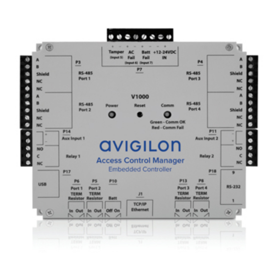
Introduction The Access Control Manager (ACM) Embedded Controller from Avigilon is an all-in-one security management application and controller. The ACM Embedded Controller is a controller embedded with the ACM Embedded Controller application to provide a flexible and scalable platform for an economic and high performance access control system. - Page 6 Installation Before you install the ACM Embedded Controller, read through this entire document. Refer to the checklist at the end of this document and gather the required information before proceeding with these instructions. The controllers and interface panels are sensitive to Electrostatic Discharges (ESD). Observe precautions while handling the circuit board assembly by using proper grounding straps and handling precautions at all times.
- Page 7 Mounting the Control Panel Case Follow the steps below to mount the control panel case. 1. At the installation site, remove the control panel case from the LifeSafety Power FlexPower box. 2. Find two studs in the wall where the enclosure should be installed. In a finished setup, the enclosure and contents together weighs 11.8kg (26lb).
- Page 8 7. Setup the high voltage junction box (or equivalent), as required. Attach an appropriate cable gland to the junction box and feed the three AC wires through. Do not connect to the main power supply yet. 8. Remove knockout(s) for low voltage input/output wires, as necessary. 9.
-
Page 9: Setup The Fpo75 Power Supply Board
Power Supply Board Overview Shown below is an overview of the power supply board. FPO75 B100 Setup the FPO75 Power Supply Board Follow the steps below to setup the FPO75 power supply board: 1. Either: For 120V input, leave JP1 intact. For 230V input, cut JP1. - Page 10 2. Ensure the DC output jumper is set to 24V (as circled below). Failure to set the FPO75’s DC output jumper to 24V will likely result in damage to the system and will void the warranty. 3. Connect the inputs on the FAI (Fire Alarm Input) to the building’s fire alarm system, as required. See the FPO Quick Start Manual (page 3 –...
-
Page 11: Setup The B100 Power Supply Board
Setup the B100 Power Supply Board On the B100 board, ensure Output Voltage Selection jumper (JP3) is set to position 1 for 12VDC out, as shown below. See the B100 Quick Start Manual or B100 Installation Manual for more detail (available at http://www.lifesafetypower.com/docs/im_b100.pdf) . -
Page 12: Setup The C4 Power Supply Board
Setup the C4 Power Supply Board Set the jumpers properly for your installation as outlined below: Either: Red - 1A to 4A (Zone FAI enabled) 1. FAI enabled 2. FAI disabled Either: Blue - 1B to 4B (Input Invert) 1. Fail Safe (NC contact input) 2. - Page 13 V100 Install the ACM Embedded Controller and V100 subpanels as shown below: 1. Unbox the Avigilon ACM Embedded Controller and V100 subpanels. 2. Locate 12 screws from the accessory bag in the FlexPower box. 3. Verify battery jumper (Batt) on the ACM Embedded Controller has been set to ON position.
-
Page 14: Configure And Wire Data
6. Mount the ACM Embedded Controller as shown below (the arrows show screws). Embedded Controller V100 Address 0 V100 Address 1 7. Mount the V100 subpanels as shown in step 4. 8. Using a small slotted screwdriver gently turn the V100 addresses as follows: Set the top V100 to Address 0 (as shown in step 4). - Page 15 2. Using 18 AWG wires (red for + and black for -), wire the 12-24VDC input to +Out1- on the D8P board’s terminal block. Tamper Batt +12-24VDC (Input 5) Fail Fail (Input 6) (Input 7) Embedded Controller 3. On the FPO75’s SYSFLT terminal block: Wire C to Batt Fail + (22 AWG).
- Page 16 5. Starting from the ACM Embedded Controller's P3\RS-485 Port1 terminal block, connect the A, B, and Shield inputs to the V100 Subpanels as shown below (22 AWG). RS-485 Shield Port 1 Embedded Controller V100 (Addr 0) RS-485 In A B Shield V100 (Addr 1) RS-485 In...
-
Page 17: Configure And Wire Power
Configure and Wire Power Do the following for each V100 in order for the ACM Embedded Controller application to not show an alarm: 1. Place a jumper across Tamper + and - (22AWG). 2. Place a jumper across AC Fail + and - (22AWG). 3. - Page 18 6. If request-to-exit inputs from the door are available, connect them appropriately to the P2\REX and P5\REX. (Refer to the appropriate Request-to-Exit device manual.) 7. Connect cabling from the R10 readers at the door to the appropriate P1/P4 reader connection on the V100.
- Page 19 Power On Follow the steps below to power on and verify the installation: : Once connected, the card readers may beep – this will go away once the ACM Embedded Controller has been configured. 1. Connect the High Voltage AC input to the main power supply. Take necessary precautions when handling high voltage wiring.
-
Page 20: By Virtual Port
Accessing ACM Embedded Controller Application for the First Time After the controller has been installed, you need to access the ACM Embedded Controller application to complete the system configuration. You can access the application by using the controller hostname or virtual port. By Virtual Port By default, every controller can be accessed from this IP address: 169.254.242.121 To perform this procedure, you must use a Windows computer with a web browser and a network port. -
Page 21: Tools Checklist
The following equipment is provided: One AC-LSP-4DR-HID-LCK LifeSafety Power four door □ HID dual voltage integrated power system (supplied in Required a separate shipping box) One Avigilon AC-HID-ACMEC V1000 ACM Embedded □ Required Controller □ Two AC-HID-VERTX-V100 reader interface modules Required □... - Page 22 The following equipment is also required: One Plywood board 4’ x 4’ (½” to ¾” thick). Fire rated □ Required recommended. □ Four Wood screws (sizing as required) Required □ Four Drywall anchors (sizing as required) Required □ High voltage wiring (sizing as required) Required □...
Need help?
Do you have a question about the AC-HID-LSP-ACMEC-KIT4 and is the answer not in the manual?
Questions and answers