Table of Contents
Advertisement
Quick Links
Advertisement
Table of Contents

Subscribe to Our Youtube Channel
Summary of Contents for ATX MAXNET MNRS
- Page 1 D3.1/CCAP ™ ® ® Compliant Pat. #s U.S. 6,842,348; 7,043,236; Pat. #s U.S. 6,842,348; 7,043,236; Cdn. 2,404,840; 2,404,844 Cdn. 2,404,840; 2,404,844 MNRS Redundant RF Detector/Switch Module INSTALLATION & OPERATION MANUAL www.atx.com www.atxnetworks.com ATX Confi dential & Proprietary...
- Page 2 ® service mark of ATX in the United States and/or other countries. Products or features contained herein may be covered by one or more U.S. or foreign patents. Other non-ATX product and company names in this manual are the property of their respective companies.
-
Page 3: Table Of Contents
4.1. Redundant Amplifier Configurations ....................4-1 4.2. RF Detector A/B Switch Configurations ..................... 4-1 SERVICE & SUPPORT ..........................5-1 5.1. Contact ATX Networks ........................5-1 5.2. Warranty Information ......................... 5-1 MAXNET – MNRS Redundant RF Detector/Switch Module – Installation & Operation Manual ®... - Page 4 Figures #1 MNRS Functional Schematic Diagram ............1-1 #2 MNRS Wiring Configuration.................2-1 #3 MNRS Wiring Configuration.................2-2 #4 MNRS Front Panel Bar Graph Display ............3-1 MAXNET – MNRS Redundant RF Detector/Switch Module – Installation & Operation Manual ® ATX Confidential & Proprietary...
-
Page 5: Operation
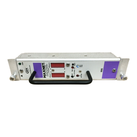
Operational Details The MAXNET MNRS RF switch provides redundancy in an RF amplifier system. When a failure occurs in the primary amplifier (A) control transfers to a secondary backup amplifier (B). The failure of the amplifier is determined by measuring the total composite RF power at the output of the primary (A) amplifier and comparing it to the set RF power threshold level. - Page 6 CHAPTER 1: OPERATION This page left intentionally blank. MAXNET – MNRS Redundant RF Detector/Switch Module – Installation & Operation Manual ® ATX Confi dential & Proprietary...
-
Page 7: Set-Up
Once the MAXNET chassis is powered, the amplifiers are connected to the MNRS (see Figure #2 below), review Section 3 for procedures on how to set the threshold level. Figure #2: MNRS Wiring Configuration MAXNET – MNRS Redundant RF Detector/Switch Module – Installation & Operation Manual ® ATX Confidential & Proprietary... -
Page 8: Rf Detector A/B Switch Applications
Once the MAXNET chassis is powered and the MNRS is configured as shown in Figure #3, review Section 3 for procedures on how to set the threshold level. Figure #3: MNRS Wiring Configuration MAXNET – MNRS Redundant RF Detector/Switch Module – Installation & Operation Manual ® ATX Confidential & Proprietary... -
Page 9: Threshold Level Settings
DVM of -150 mV (-3 dB) NOTE: Voltage scaling for RF and THD test points is 50 mV/dB MAXNET – MNRS Redundant RF Detector/Switch Module – Installation & Operation Manual ® ATX Confidential & Proprietary... - Page 10 CHAPTER 3: THRESHOLD LEVEL SETTINGS This page left intentionally blank. MAXNET – MNRS Redundant RF Detector/Switch Module – Installation & Operation Manual ® ATX Confi dential & Proprietary...
-
Page 11: Device Reset
4.2. RF Detector A/B Switch Configurations No reset required. Device returns to primary mode when signal source A returns to a power level above the threshold level. MAXNET – MNRS Redundant RF Detector/Switch Module – Installation & Operation Manual ® ATX Confidential & Proprietary... - Page 12 CHAPTER 4: DEVICE RESET This page left intentionally blank. MAXNET – MNRS Redundant RF Detector/Switch Module – Installation & Operation Manual ® ATX Confi dential & Proprietary...
-
Page 13: Service & Support
Please contact ATX Technical Support for assistance with any ATX products. Please contact ATX to obtain a valid RMA number for any ATX products that require service and are in or out-of-warranty before returning a failed module to ATX. TECHNICAL SUPPORT Tel: 289.204.7800 –... - Page 14 9001:15 REGISTERED ATX Networks © 2019 by ATX Networks Corp. and its affiliates (collectively “ATX Networks Corp.”). Tel: 289.204.7800 | Toll-Free: 866.YOUR.ATX (866.968.7289) | support@atx.com All rights reserved. This material may not be published, broadcast, rewritten, or redistributed. Information in this document is subject to change without notice.

Need help?
Do you have a question about the MAXNET MNRS and is the answer not in the manual?
Questions and answers