Advertisement
Quick Links
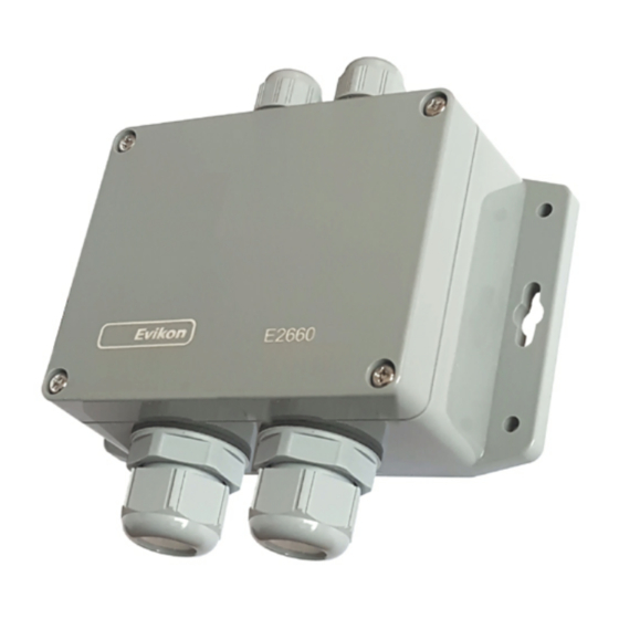
Dual Gas Transmitter E2660-CO-CO2 belongs to the PluraSens® family of
multifunctional measurement instruments.
The device is intended for simultaneous detection of carbon dioxide and carbon
monoxide. It is a convenient solution for underground parkings
The instrument utilizes electrochemical gas sensors with excellent repeatability,
stability and long lifetime
Two analog outputs and RS485 digital interface with industry standard Modbus
RTU protocol can be used to connect the transmitter to safety or building
automation systems.
Safety requirements
Always adhere to the safety provisions applicable in the country of use.
Do not perform any maintenance operation with the power on. Do not let water or
foreign objects inside the device.
Operating conditions
The device should be used in explosion-safe (non ATEX rated) indoor areas, at the
pressure 0,9...1,1 atm and relative humidity in the range 15...90% without
condensation. (See also Specifications table.)
Avoid strong vibrations, mechanical shock, and the sources of strong
electromagnetic interference.
For best stability the gas detector should be powered permanently.
Installation guidelines
There are no precise rules to follow when installing the gas detectors. The
geometry of the room, detected gases, environment condition should be taken into
account. The device should be mounted on a wall at a place where it is available
for maintenance and repair. Place the transmitter (or remote sensor probes) not
more than 5 m from a possible leakage source and not very close to ventilation
openings or strong air currents. Avoid the areas without air circulation (corners,
niches) as well. Recommended sensor position is vertical pointing downwards.
Carbon monoxide has practically the same density as air. Carbon dioxide is ca. 1.5
times heavier than air.
Mounting and connection
1. Unscrew four lid screws and detach the lid from the device.
2. Attach the device to the wall using four round holes or two key slots. The
mounting dimensions of the device are shown below. (This step may be done after
the step 3, consider your convenience).
3. Use two M16 cable glands to let in the cables of the power supply and of the
external devices. Attach the power cable to the device without turning it on. Using
the connection diagram below, connect the analog outputs and/or digital interface
terminals to the relevant devices according to your tasks.
145
130
115
30
M16
M25
38
OUT1
OUT2
J3
0V
Control LED
A
B
+U
L
SENSORS
90...265 VAC
N
not in use
J1 J2
J1: OUT1 type (open: 4-20 mA; closed: 0-10 V)
J : OUT type
2
2
(open: 4-20 mA; closed: 0-10 V)
J : 3 return to factory settings
The screwless quick connect spring terminals on the E2660 series devices are
suitable for a wide range of wires with cross-section 0,2...1,5 mm
to strip the wire end by 8...9 mm and tin it, or to use the wire end sleeves.
To connect the wire, insert the wire end into terminal hole. To disconnect, push the
spring loaded terminal lever, pull the wire out, and release the lever.
Use twisted pair cable, e.g. LiYY TP 2×2×0,5 mm
to RS485 network. Use one pair for A and B wires and the second pair for common
0 V and power +U wires to connect the transmitter to Fieldbus network. Respect
polarity. Overall length of all connections via RS485 interface should not exceed
1200 m.
The type of each analog output can be independently changed between 4-20 mA
and 0-10 V with jumpers J1 (OUT1) and J2 (OUT2).
With closed jumper the output is 0-10 V, with open jumper the output is 4-20 mA.
By default both outputs OUT1 and OUT2 are assigned to CO and NO
concentration respectively.
The output assignments and scales can be changed by Modbus commands (see
Annex 1 for more details).
We recommend to set the difference between the upper and bottom limits of the
output scale not narrower than 20% of detection range (for CO detectors the
scales down to 5% of range are allowed). In any case, do not set the output scale
below the tenfold resolution of the device
Note The outputs are not galvanically isolated from 24 V power supply and share
common 0V. Allowed load resistance limits are stated in Specifications table. To
power the instrument from an external 24 VDC source, connect terminals 0V and +U to
the source. If the integrated mains power supply module is used, connect terminals L
and N to the mains.
3. Turn on the power. The sensor heating up takes ca. 60 seconds after switching
on. A LED placed on the PCB of the device allows to control the connection
process. The LED response to different processes is presented in the table below.
Process
55
Sensor absence or malfunction
Modbus response
Normal operating
4. Make sure that the transmitter is properly fixed, the external devices connected,
power on and control LED is constantly lit. Make certain that the cable glands are
properly tightened to ensure the conformity to IP65 protection class. Place the lid
back and fix it with the screws. The device is ready to use.
It is recommended to keep the transmitter powered constantly, except for periods
of maintenance and calibration, deplacement etc.
Input 1 4-20 mA / 0-10 V
Controller
Input 4-20 mA / 0-10 V
2
0V / GND
0V
Fieldbus
Power
+24V
Supply
Power s upply unit
90...265 VAC
2
. We recommend
2
or CAT 5, to connect the device
LED mode
Blinking 0.5 Hz (90% off, 10% on)
The signal is modulated with short
on/off pulses, even single Modbus
cycle is traceable
Continuous light
Sensor probe handling
The transmitter is available with remote probe (see drawing for dimensions).
36
The remote probe is connected to the main unit with shielded cable. Default cable
length is 3 m.
The sensor probes are equipped with a hydrophobic microporous PTFE filter to
protect the sensor from dust, dirt and water drops. The filter may be replaced if it
gets strongly contaminated.
To replace the PTFE filter, unscrew the M25 nut and remove the old filter. Place a
new filter into the nut and tighten it again.
NB! Never stab or press the filter near its center where the sensor is located since
this may damage the sensor.
The recommended orientation of sensor probe is vertical with the sensor tip
pointing downwards. This prevents possible accumulation of condensed water on
2
the sensor protection filter. The horizontal orientation is also suitable. Avoid upward
position of the sensor tip.
Return to default settings
To reset the device's Slave ID, baudrate and sbit number to factory settings,
proceed as follows:
1. De-energize the device
2. Connect the J3 jumper
3. Turn on the device
4. De-energize the device
5. Disconnect the J3 jumper
6. Turn on the device
Maintenance
Do not perform any maintenance operation with the power on.
Clean the device with soft damp cloth. Do not use any abrasive cleaning agents.
Do not immerse the device into water or any cleaning media.
Calibration
E2660 series transmitters have been calibrated by Manufacturer with standard gas
mixtures before delivery. Electrochemical gas sensors require field recalibration
every 6 months. Optical sensor may be calibrated every five years, if used under
moderate conditions without strong temperature fluctuations. Please contact your
dealer for more information.
Delivery set
– Transmitter E2660-CO-CO2
– Mounting accessories:
- 4 screws with plastic dowels
- fixing clamp for remote probe versions
Ø34 max
120°
Ø35...36
Ø50
Hole
Advertisement

Related Manuals for Evikon E2660-CO-CO2


Summary of Contents for Evikon E2660-CO-CO2
- Page 1 Dual Gas Transmitter E2660-CO-CO2 belongs to the PluraSens® family of Sensor probe handling Input 1 4-20 mA / 0-10 V multifunctional measurement instruments. OUT1 Controller Input 4-20 mA / 0-10 V OUT2 The transmitter is available with remote probe (see drawing for dimensions).
- Page 2 Exposure limits 40 mg/m /35 ppm (NIOSH) IDLH 1380 mg/m /1200 ppm Evikon MCI OÜ Teaduspargi 7/9, Tartu info@evikon.eu * Calculated for 25°C and 1 atm. Tel.: +372 733 6310 50411 Estonia www.evikon.eu...
- Page 3 E2660_UM_EN Annex 1 E2660 series Modbus RTU Communication Reference Modbus holding registers Register addresses are shown 0-based, Addr in hexadecimal, Reg in decimal format. RS485 communication interface Modbus holding register numbers MHR are shown in decimal 1-based format, and may be addressed either from 00001 or 40001 base. Databits: 8 Supported Modbus functions: Addr...
- Page 4 E2660 series Modbus holding registers (part 2) Register addresses are shown 0-based, Addr in hexadecimal, Reg in decimal format. Modbus holding register numbers MHR are shown in decimal 1-based format, and may be addressed either from 00001 or 40001 base. Addr Reg / MHR RW Description Supported values (dec)
Need help?
Do you have a question about the E2660-CO-CO2 and is the answer not in the manual?
Questions and answers