Table of Contents
Advertisement
Quick Links
Advertisement
Table of Contents

Related Manuals for Cansec SmartLock UltraLite Plus


Summary of Contents for Cansec SmartLock UltraLite Plus
- Page 1 SmartLock UltraLite Plus ® INSTALLATION MANUAL October 2015...
-
Page 2: Table Of Contents
DC Electric Strikes (more than 250mA) ............11 AC Electric Strikes ................... 12 AC Maglocks ....................13 TROUBLESHOOTING ..........................14 SMARTLOCK ULTRALITE PLUS COMPLIANCE STATEMENT ............... 15 Copyright 2012 - 2015 Cansec Systems, Ltd. All rights reserved. ® SmartLock UltraLite Plus... -
Page 3: Introduction
UltraLite Plus system becomes one of the most cost-effective stand-alone, expandable systems on the market. The SmartLock UltraLite Plus controller features a form "C" relay output for lock control as well as inputs for a request-to-exit button and a door contact. If a door contact input is connected, the controller will automatically relock the door once it re- closes. -
Page 4: Specifications
Specifications Power Requirements UltraLite Plus controller ................ 12 VDC, 40 mA NOTE: When determining power supply current requirements, add lock and reader current draw. IMPORTANT: In some jurisdictions the use of a UL-approved power supply and connection to the fire alarm system for emergency release may be required. -
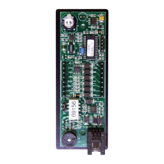
Page 5: Board Layout
Board Layout NOTE: 1. Only connect a power source to the indicated power pins or product damage will result. 2. The door contact input must be bypassed if not used. To bypass, connect a jumper wire between the door contact input and Ground. 3. -
Page 6: Wiring
Wiring CONNECTOR INSTALLATION NOTE ATTACH CONNECTORS AS SHOWN CONNECT WIRES ONTO THE PLUGGABLE CONNECTORS IN THIS ORIENTATION IMPORTANT: Wires face into the center of the PCB for installation into housing. ® SmartLock UltraLite Plus Page 6 of 16 Installation Manual Oct 2013 •... -
Page 7: Wiegand Reader
WIEGAND READER 6 CONDUCTOR, 20 AWG NON-TWISTED PAIR SHIELDED CABLE MAX. DISTANCE IS 500 FT. IMPORTANT: Before applying power to the controller, verify that the reader is connected correctly as per the manufacturer’s specifications. ® SmartLock UltraLite Plus Page 7 of 16 Installation Manual Oct 2013 •... -
Page 8: Ibutton Reader
IBUTTON READER 6 CONDUCTOR, 22 AWG TWISTED OR NON-TWISTED PAIR SHIELDED CABLE MAX. DISTANCE IS 50 FT. ® SmartLock UltraLite Plus Page 8 of 16 Installation Manual Oct 2013 • Rev. 1.6... -
Page 9: Exit Button And Door Contact
EXIT BUTTON AND DOOR CONTACT NOTE: 1. Do not apply power or attempt to switch any current through these inputs as this will result in damage to the controller. 2. The door contact input is used for forced entry and door-held-open annunciation. -
Page 10: Lock Relay Wiring
Lock Relay Wiring DC ELECTRIC STRIKES (UP TO 250MA) NOTE: Use a 1N400x series diode at the lock device as shown to prevent “back EMF” from damaging the controller. ® SmartLock UltraLite Plus Page 10 of 16 Installation Manual Oct 2013 • Rev. 1.6... -
Page 11: Dc Electric Strikes (More Than 250Ma)
DC ELECTRIC STRIKES (MORE THAN 250MA) NOTE: Place a 1N400x series diode at the external relay coil as shown to prevent “back EMF” from damaging the controller. ® SmartLock UltraLite Plus Page 11 of 16 Installation Manual Oct 2013 • Rev. 1.6... -
Page 12: Ac Electric Strikes
AC ELECTRIC STRIKES NOTE: Place a 1N400x series diode at the external relay coil as shown to prevent “back EMF” from damaging the controller. ® SmartLock UltraLite Plus Page 12 of 16 Installation Manual Oct 2013 • Rev. 1.6... -
Page 13: Ac Maglocks
AC MAGLOCKS IMPORTANT: In some jurisdictions the use of a UL-approved power supply and connection to the fire alarm system for emergency release may be required. Installers should contact the fire marshal office or local authority having jurisdiction to verify the specific requirements. A building permit may be required in some jurisdictions for the installation of maglocks. -
Page 14: Troubleshooting
Troubleshooting The SmartLock UltraLite Plus uses a series of ON/OFF tones (beeps) to indicate operational status to the user. These beeps can be used for troubleshooting. NOTE: The UltraLite Plus controller emits two types of beeps: high (2,300 Hz) and low (675 Hz). -
Page 15: Smartlock Ultralite Plus Compliance Statement
Compliance statements for : Federal Communications Commission (FCC) Statement Note: This equipment has been tested and found to comply with the limits for a class B digital devices, pursuant to Part 15 of the FCC Rules. These limits are designed to provide reasonable protection against harmful interference in a residential installation. - Page 16 Industry Canada Compliance Statement This Class B digital apparatus meets the requirements of the Canadian Interference-Causing Equipment Regulations. Avis de conformité à la réglementation d'Industrie Canada Cet appareil numérique de la classe B respecte toutes les exigences du Réglement sur le matériel brouilleur du Canada.
Need help?
Do you have a question about the SmartLock UltraLite Plus and is the answer not in the manual?
Questions and answers