Table of Contents
Advertisement
Quick Links
Advertisement
Table of Contents

Subscribe to Our Youtube Channel
Related Manuals for Eletta EMF Series


Summary of Contents for Eletta EMF Series
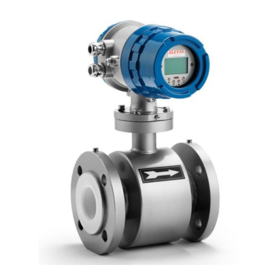
- Page 1 Manual EMF Series Electromagnetic Flow Meters EMFA2E21...
-
Page 2: Table Of Contents
Content Page 1. General Information 1.1. Product Description 1.2. Unpacking and Inspection 1.3. Transport and Handling 2. Technical Data 2.1. Measuring system 2.2. Design 2.3. Measuring Accuracy 2.4. Operating conditions 2.5. Installation conditions 2.6. Materials 3. Models and Selection 4. Cautions for Installation 4.1 Mounting Positions 4.2. -
Page 3: General Information
1. General Information This manual will assist you in installing, using and maintaining the Eletta flow meter. lt is your responsibility to make sure that all operators have access to adequate instructions about safe operating and maintenance procedure. For your safety, review the major warnings and cautions below before using your equipment. -
Page 4: Technical Data
Warning: NEVER insert the forklift`s fork, chains, wire slings or any other sharp object inside the flow tube for lifting or handling purpose. This could permanently damage the isolating liner and could render the meter inoperable. lf using a forklift, do not lift the detector on its body between the flanges. The housing could be accidentally dented and permanent damage could be caused to the internal coil assemblies. -
Page 5: Operating Conditions
2.4. Operating conditions Process temperature Hard rubber liner: -5 ... +60°C Polypropylene liner: -5 ... +90°C PTFE liner: -5 ... +120°C Ambient temperature -20 ... +60°C (Protect electronics against self-heating with ambient temperatures >55°C) Storage ternperature -20 ... +70°C Pressure PN16 Pressure drop negligible... -
Page 6: Models And Selection
3. Models and Selection... -
Page 7: Cautions For Installation
4. Cautions for Installation 4.1 Mounting Positions Pipes must be fully filled with liquids. It is essential that pipes remain fully filled at all times, otherwise flow rate indications may affected, and measurement errors may be caused. Avoid Air Bubbles. If air bubbles enter a measurement pipe, flow rate indications may be affected and measurement errors may be caused. -
Page 8: Required Lengths Of The Straight Runs
4.2. Required Lengths of the Straight Runs For optimum accuracy, it is required to provide sufficient inlet and outlet straight pipe runs. An equivalent to 5 diameters of straight pipe is required on the inlet side, and 2 diameters on the outlet side. There are no special requirements for standard concentric pipe reducers. -
Page 9: Connections
4.4 Connections Use a gasket between the meter flange and mating flange Determine the material of the gasket based on the operating conditions and type of fluid. Do not overtighten the flange bolts. This may cause the gaskets to be compressed into the flow stream and may decrease the accuracy of the meter. -
Page 10: Electrical Wiring
5. Electrical Wiring 5.1. Safety Instructions All work on electrical connections may only carried out when the power disconnected. Observe the national regulations for electrical installations! Observe the local health and safety regulations. Any work done on the electrical components of the measuring device may only be carried out by properly trained specialists. -
Page 11: Remote Converter Terminal Configuration
5.2.2. Remote Converter Terminal Configuration Pulse Output POUT Frequency Pulse Output for Bi-Directional Flow PCOM Pulse Output Ground Alarm Output ALMH Alarm Upper Limit ACOM Alarm Output Ground RS485 (optional) TRX+ Communication RS485+ TRX- Communication RS485- Analog Current Output VDIN 24VDC Power Supply for 2-Wire 4-20mA Output IOUT Analog Current Output... -
Page 12: Digital Pulse Output
6.1.2. Digital Pulse Output 6.1.3. Alarm Output 6.2. Output Connection 6.2.1. Current Output... -
Page 13: Digital Voltage Output
6.2.2. Digital Voltage Output 6.2.3. Digital Voltage Output to Photoelectric Coupling Generally, photoelectrical coupling current is 10mA. When E/R=10mA, E= 5-24VDC 6.2.4. Digital Output to Relay Generally, E (Vollage) of lhe relay is 12V or 24V; D is exlended diode, rnost midd le relays have this diode inside. -
Page 14: Operation And Setup
7.0 Operation and Setup 7.1. Display and Keys 7.1.1. Compact Version 7.1.2. Remote Type... -
Page 15: Function Selection Menu
7.2. Function Selection Menu 7.3. Parameters Setting Press > and Enter, this leads to functions election menu and the first menu is “Parameters Set”, press Enter to confirm this menu. Enter the password and press > + Enter. There are 54 menus totally in “Parameters Set” and users can access and modify these menus depending on the input password grade. - Page 16 Specific Menu – Parameters Set Menu Parameter Name Setting Method Grades Range Language Select Parameter English Comm Address Input Value 0-99 Baud Rate Select Parameter 600-14400 SNSR Size Select Parameter 3-3000 Flow Unit Select Parameter l/h, l/min, l/s, m³/h, m³/min, m³/s Flow Range Input Value 0-99999...
-
Page 17: Parameter Function Table
7.4. Parameter Function Table Menu Function Settings/Description Language English/Chinese Language selection Comm Address RS485 Value: Integer 01-++ Device Address for RS485 (if present) Baud Rate Select: 600, 1200, 2400 ,4800 ,9600, 19200 SNSR Size Selsnor Size, select according to Nameplate Flow Unit Selectable flow unit Flow Range... - Page 18 Menu Function Settings/Description M31 Linearity CRC1 Correction Point 1: the velocity of point1 M32 Linearity Fact 1 The correction factor for point 1 M33 Linearity CRC2 Correction Point 1: the velocity of point2 M34 Linearity Fact 2 The correction factor for point 2 M35 Linearity CRC3 Correction Point 1: the velocity of point3 M36 Linearity Fact 3 The correction factor for point 3...
-
Page 19: Alarm Information
8. Alarm information The converter has a self-diagnose function. This signal shows at the left of the LCD display: Alarm messages: Upper Flow Limit Alarm Low Flow Limit Alarm Empty Pipe Alarm System Alarm 9. Troubleshooting... -
Page 20: Contact
Eletta Messtechnik GmbH Grosbeerenstrase 169 DE-12277 Berlin, Deutschland Tel: +49 30 757 66 566 Fax: +49 30 2025 3333 info@eletta.de, www.eletta.de Eletta Instrumentation India Private LImited #175, Tower-A, The Corenthum A-41, Sector-62 Noida (U.P.) - 201301 E-Mail india@eletta.com www.eletta.com Telefon +91 120 4292444...
Need help?
Do you have a question about the EMF Series and is the answer not in the manual?
Questions and answers