Sign In
Upload
Download
Table of Contents
Contents
Add to my manuals
Delete from my manuals
Share
URL of this page:
HTML Link:
Bookmark this page
Add
Manual will be automatically added to "My Manuals"
Print this page
×
Bookmark added
×
Added to my manuals
Manuals
Brands
LG Manuals
Air Conditioner
B30AWYN7G5A
Manual
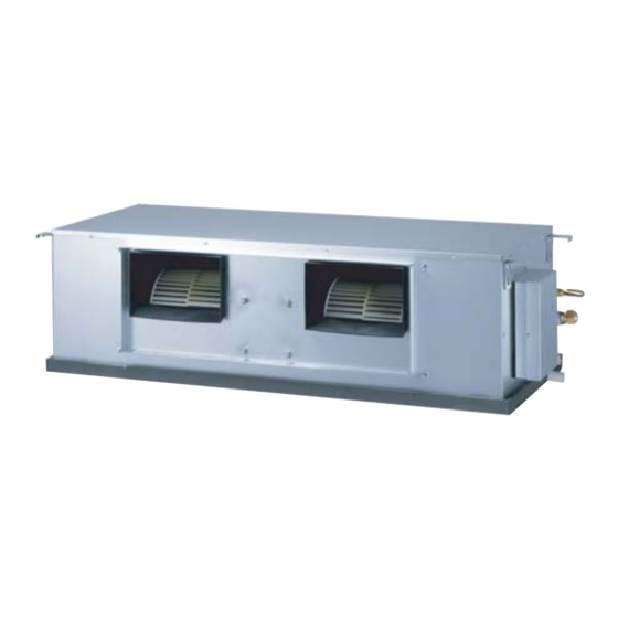
LG B30AWYN7G5A Manual
Ceiling concealed duct. inverter 50hz/r410a 5csb0-02b(replace: 5csb0-02a)
Hide thumbs
1
2
3
4
5
6
7
8
9
10
11
12
13
14
15
16
17
18
19
20
21
22
23
24
25
26
27
28
29
30
31
32
33
34
35
36
37
38
39
40
41
42
43
44
45
46
47
48
49
50
51
52
53
54
55
56
57
58
59
60
61
62
63
64
65
66
67
68
69
70
71
72
73
74
75
76
77
78
79
80
81
82
83
84
85
Table Of Contents
86
page
of
86
Go
/
86
Contents
Table of Contents
Bookmarks
Table of Contents
Ceiling Concealed Duct
Part 1 General Information
Indoor Units
Outdoor Units
Part 2 Product Data
Operation Range
Indoor Unit
List of Functions
Outdoor Unit
Specifications
Dimensional Drawings
Wiring Diagrams
Inverter Pcb
Refrigerant Cycle Diagrams
Performance Data
Cooling Capacity
Heating Capacity
The Coefficient of Capacity Change
External Static Pressure & Air Flow
Fan Performance Curve
Deluxe Wired Remote Controller
Sound Levels
Outdoor Unit
Sound Power Level
Select the Best Location
Settlement of Outdoor Unit
Indoor Unit Installation
Clamping of Cables
Electrical Wiring
Indoor Unit Drain Piping
Optional Operation
Zone Control
Two Wired Remote Controller
Selecting the Location(Outdoor Unit)
Advertisement
Quick Links
1
Ceiling Concealed Duct
2
Part 1 General Information
3
Indoor Units
4
Outdoor Units
5
List of Functions
6
Deluxe Wired Remote Controller
7
Optional Operation
8
Zone Control
Download this manual
Ceiling Concealed Duct
Inverter 50Hz/R410A
5CSB0-02B(Replace: 5CSB0-02A)
P/No. : MFL49500009
Table of
Contents
Previous
Page
Next
Page
1
2
3
4
5
Advertisement
Table of Contents
Need help?
Do you have a question about the B30AWYN7G5A and is the answer not in the manual?
Ask a question
Questions and answers
Related Manuals for LG B30AWYN7G5A
Air Conditioner LG B30AWYN762 Installation Manual
(35 pages)
Air Conditioner LG B36AWYU4G5A Manual
Ceiling concealed duct. inverter 50hz/r410a 5csb0-02b(replace: 5csb0-02a) (86 pages)
Air Conditioner LG B42AWYN7G6 Owner's Manual
(16 pages)
Air Conditioner LG B30AWYN7G5 Installation Manual
(43 pages)
Air Conditioner LG B36AWYU4G5 Installation Manual
(43 pages)
Air Conditioner LG BG5200ER Owner's Manual
Window-type room air conditioner (47 pages)
Air Conditioner LG HBLG5200E Service Manual
Room air conditioner (31 pages)
Air Conditioner LG LG-BKE 9300 D Owner's Manual
Floor standing-type air conditioner (27 pages)
Air Conditioner LG BNU-BAC Installation & Owner's Manual
(109 pages)
Air Conditioner LG B62AWYN9L6 Owner's Manual
(16 pages)
Air Conditioner LG B62AWYN9L6 Installation Manual
(57 pages)
Air Conditioner LG B55AWYU3G5A Manual
Ceiling concealed duct. inverter 50hz/r410a 5csb0-02b(replace: 5csb0-02a) (86 pages)
Air Conditioner LG B12TS Owner's Manual
Wall mounted (233 pages)
Air Conditioner LG S4-W12JA1ZD Manual
Room air conditioner (9 pages)
Air Conditioner LG BS-W096WEA0 Owner's Manual
Wall mounted (120 pages)
Air Conditioner LG BS24DHL Service Manual
Ceiling duct type air conditioner (41 pages)
This manual is also suitable for:
B36awyn7g5a
B42awyn7g5a
B55awyn7g5a
B30awyu4g5a
B36awyu4g5a
B42awyu4g5a
...
Show all
B55awyu3g5a
Table of Contents
Print
Rename the bookmark
Delete bookmark?
Delete from my manuals?
Login
Sign In
OR
Sign in with Facebook
Sign in with Google
Upload manual
Upload from disk
Upload from URL


Need help?
Do you have a question about the B30AWYN7G5A and is the answer not in the manual?
Questions and answers