Table of Contents
Advertisement
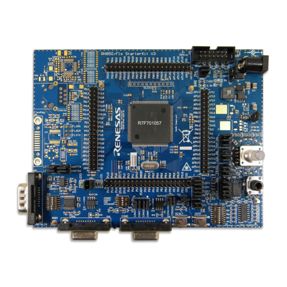
RH850/F1x StarterKit V3
32
RENESAS MCU
RH850 F1x Series
All information contained in these materials, including products and product specifications,
represents information on the product at the time of publication and is subject to change by
Renesas Electronics Corp. without notice. Please review the latest information published by
Renesas Electronics Corp. through various means, including the Renesas Electronics Corp.
website (http://www.renesas.com).
For updates of the StarterKit software and documentation please check:
http://www.renesas.com/ASK-RH850F1X
User Manual: Hardware
Y-ASK-RH850F1L-V3
Y-ASK-RH850F1K-V3
Y-ASK-RH850F1H-V3
Y-ASK-RH850F1KM-S4-V3
Y-ASK-RH850F1KH-D8-V3
Advertisement
Table of Contents

Related Manuals for Renesas RH850 F1 Series


Summary of Contents for Renesas RH850 F1 Series
- Page 1 All information contained in these materials, including products and product specifications, represents information on the product at the time of publication and is subject to change by Renesas Electronics Corp. without notice. Please review the latest information published by Renesas Electronics Corp. through various means, including the Renesas Electronics Corp.
- Page 2 Renesas Electronics. Renesas Electronics shall not be in any way liable for any damages or losses incurred by you or third parties arising from the use of any Renesas Electronics product for an application categorized as “Specific”...
-
Page 3: Table Of Contents
RH850/F1x StarterKit V3 User Manual Table of Contents Introduction ..........................4 Cautions ..........................5 Quick Start Information ......................6 Connector and jumper overview ....................6 Board Overview RH850/F1L Version [Y-ASK-RH850F1L-V3] ..........10 Board Overview RH850/F1K Version [Y-ASK-RH850F1K-V3] ..........11 Board Overview RH850/F1H Version [Y-ASK-RH850F1H-V3] ..........12 Board Overview RH850/F1KM-S4 Version [Y-ASK-RH850F1KM-S4-V3] ...... -
Page 4: Introduction
1x FlexRay (RH850/F1H, F1KM-S4 and F1KH-D8 version only) − 1x Ethernet 100Base-T (RH850/F1H, F1KM-S4 and F1KH-D8 version only) • Power supply by RENESAS E1 On-Chip debugger or externally (12V DC input) • Support of different RH850/F1x family members − RH850/F1L −... -
Page 5: Cautions
RH850/F1x StarterKit V3 User Manual 2. Cautions 1. Do not look into the LED beam! Special care must be taken with the high power LEDs 2. When power supply of E1 On-Chip debugger is used please note that the maximum current provided by the debugger is limited to 200mA. -
Page 6: Quick Start Information
RH850/F1x StarterKit V3 User Manual 3. Quick Start Information 3.1 Connector and jumper overview Function Function P12_5 P11_0 P11_1 P11_2 P12_3 P12_4 P11_3 P11_4 P12_1 P12_2 P11_5 P11_6 P10_15 P12_0 P11_7 P11_8 P10_13 P10_14 P11_9 P11_10 P10_11 P10_12 P11_11 P11_12 P11_13 P11_14 P10_9... - Page 7 RH850/F1x StarterKit V3 User Manual Function Function AP1_0 AP1_1 P1_14 P1_13 P1_12 P1_11 AP1_2 AP1_3 P1_10 P1_9 AP1_4 AP1_5 P1_7 P1_8 AP1_6 AP1_7 (not for F1Kx) P1_6 P20_5 AP1_8 P1_5 (not for F1Kx) P20_3 P20_4 P1_4 P1_3 P20_1 P20_2 P1_2 P1_1 P9_6 IP0_0...
- Page 8 RH850/F1x StarterKit V3 User Manual Jumper Description Setting Note 1 – 2 REG0VCC supply MCU power distribution (Note: setting 7-8 for further 3 – 4 EVCC/AVREF supply expansion) 5 – 6 BVCC supply 7 – 8 REG1VCC CAN0NSIL ↔ P1_1 CAN0/1 transceiver NSIL 1 –...
- Page 9 RH850/F1x StarterKit V3 User Manual LED1 ↔ P0_11 1 – 2 Indication LED to MCU Connector LED2 ↔ P8_5 3 – 4 Button ↔ P0_9 1 – 2 Interrupt Button to MCU connector LIN RX ↔ P0_7 LIN Transceiver to MCU 1 –...
-
Page 10: Board Overview Rh850/F1L Version [Y-Ask-Rh850F1L-V3]
RH850/F1x StarterKit V3 User Manual 3.2 Board Overview RH850/F1L Version [Y-ASK-RH850F1L-V3] The RH850/F1L Version of the V3 StarterKit is available in two versions: • RH850-F1X-Starter-Kit-F1L V3 Release Version EEAS-0401-002-01 • RH850-F1X-Starter-Kit-F1L V3 Release Version EEAS-0401-003-01 The difference is only related to the power supply circuit (see detailed description in chapter ‘4.2.1 Power Supply’... -
Page 11: Board Overview Rh850/F1K Version [Y-Ask-Rh850F1K-V3]
RH850/F1x StarterKit V3 User Manual 3.3 Board Overview RH850/F1K Version [Y-ASK-RH850F1K-V3] The RH850/F1K Version of the V3 Starterkit is available in two versions: • RH850-F1X-Starter-Kit-F1K V3 Release Version EEAS-0401-002-01 • RH850-F1X-Starter-Kit-F1K V3 Release Version EEAS-0401-003-01 The difference is only related to the power supply circuit (see detailed description in chapters ‘4.2.1 Power Supply’). -
Page 12: Board Overview Rh850/F1H Version [Y-Ask-Rh850F1H-V3]
RH850/F1x StarterKit V3 User Manual 3.4 Board Overview RH850/F1H Version [Y-ASK-RH850F1H-V3] The RH850/F1H Version of the V3 Starterkit is shown in the figure below. R7F701527 StarterKit V3 top view RH850/F1H R01UH0724ED0120 Page 12 January 2018... -
Page 13: Board Overview Rh850/F1Km-S4 Version [Y-Ask-Rh850F1Km-S4-V3]
RH850/F1x StarterKit V3 User Manual 3.5 Board Overview RH850/F1KM-S4 Version [Y-ASK-RH850F1KM-S4-V3] The RH850/F1KM-S4 Version of the V3 StarterKit is shown in the figure below. R7F701649 StarterKit V3 top view RH850/F1KM-S4 R01UH0724ED0120 Page 13 January 2018... -
Page 14: Board Overview Rh850/F1Kh-D8 Version [Y-Ask-Rh850F1Kh-D8-V3]
RH850/F1x StarterKit V3 User Manual 3.6 Board Overview RH850/F1KH-D8 Version [Y-ASK-RH850F1KH-D8-V3] The RH850/F1KH-D8 Version of the V3 StarterKit is shown in the figure below. R7F701709 StarterKit V3 top view RH850/F1KH-D8 R01UH0724ED0120 Page 14 January 2018... -
Page 15: Starterkit Hardware
RH850/F1x StarterKit V3 User Manual 4. StarterKit Hardware 4.1 StarterKit functions Functional Overview Note: RH850/F1L version of the Starter Kit does not support CAN-FD function. Only High Speed Can is supported. FlexRay and Ethernet function is available on RH850/F1H, F1KM-S4 and F1KH-D8 version only. R01UH0724ED0120 Page 15 January 2018... -
Page 16: Functional Areas
RH850/F1x StarterKit V3 User Manual 4.2 Functional Areas The functional areas provide various circuits and components useful for interacting with the microcontroller’s I/O: Ethernet Area FlexRay Area (Only (Only Mikrocontroller Area Power Supply Area Debug Connector available for RH850/F1H, available for RH850/F1H, F1KM-S4 and F1KH-D8) F1KM-S4 and F1KH-D8 ) Indicator LEDs... -
Page 17: Power Supply
RH850/F1x StarterKit V3 User Manual 4.2.1 Power Supply 4.2.1.1 Power supply configuration The StarterKit provides two options for powering the board’s integrated circuits. It is possible to supply the StarterKit by using the E1 Debugger or it is possible to supply the StarterKit by using an external 12 Volt power supply. - Page 18 RH850/F1x StarterKit V3 User Manual 4.2.1.2 Power supply measurement The current which is consumed by MCU can be measured by using J5. The appearance of J5 is different on the two Release Version. Please find below a description of the different versions. RH850/F1L and RH850/F1K: Jumper Description...
-
Page 19: Microcontroller Area And Port Pin Interfaces
RH850/F1x StarterKit V3 User Manual 4.2.2 Microcontroller Area and Port Pin Interfaces On the different versions of the RH850/F1x StarterKit the following device are assembled: Y-ASK-RH850F1L-V3: R7F701057 Y-ASK-RH850F1K-V3: R7F701587 Y-ASK-RH850F1H-V3: R7F701527 Y-ASK-RH850F1KM-S4-V3: R7F701649 Y-ASK-RH850F1KH-D8-V3: R7F701709 As external clock supply of the microcontroller, a 16MHz crystal oscillator and a 32.768kHz sub- oscillator is mounted. -
Page 20: Leds
RH850/F1x StarterKit V3 User Manual Power Supply of Pin Groups Port power supply groups F1KM-S4 F1KH-D8 3,3V 3,3V 3,3V BVCC (P10,P11,P12,P18) All other power supplies expect BVCC Port power supply groups Table 11. In the RH850/F1H, F1KM-S4 and F1KH-D8 versions of the board a 3.3V regulator is supplied to provide the required voltage for the Ethernet transceiver. - Page 21 RH850/F1x StarterKit V3 User Manual connected to the A/D converter of the microcontroller to evaluate the LED drive state. The LED PWM signals are active high. Please use the following jumper configuration to activate the full RGB LED functionality: Jumper Description Setting Note...
-
Page 22: Digital Inputs For Low Power Sampler (Lps)
RH850/F1x StarterKit V3 User Manual Jumper Setting Signal Device Port P1_14 BLNK P1_15 MCLK P0_14 MOSI P0_13 9-10 MISO P0_12 Table 15. Blue LED Circle Signals 4.2.4 Digital inputs for Low Power Sampler (LPS) Eight digital input signals, which are generated by a DIP switch array (S3), are provided to trigger the microcontroller’s Low Power Sampler. -
Page 23: Analog Input - Potentiometer
RH850/F1x StarterKit V3 User Manual Additionally a pushbutton is provided with the Rotary Encoder. For details please refer to Rotary Encoder with Pushbutton. 4.2.6 Analog Input - Potentiometer A potentiometer (POT1) is provided to generate an analog voltage, which can provided to the microcontroller’s analog input pins. -
Page 24: Serial Communication Interfaces
RH850/F1x StarterKit V3 User Manual 4.2.8 Serial Communication Interfaces 4.2.8.1 RS232 and LIN RS232 transceiver (IC5) is supplied to provide a serial interface. The transceiver can be connected to the microcontroller’s UART macro (RLIN30). Please close the following jumpers to connect the RS232 transceiver to the microcontroller: Jumper Description Setting... - Page 25 RH850/F1x StarterKit V3 User Manual Switch Configuration Signal DB9 pin (CN14) Ground VBAT (12V DC) Ground Table 25. Switch S10 configuration for LIN Caution: Please ensure that only one interface is configured for operation at the same time (either RS232 or LIN) by using DIP switch S10. 4.2.8.2 CAN Interfaces Controller Area Network (CAN) transceivers (IC1 and IC3) are supplied to provide two CAN bus interfaces.
- Page 26 RH850/F1x StarterKit V3 User Manual Jumper Description Setting Note CANNSIL0 ↔ P1_1 CAN0 and CAN1 transceiver NSIL to 1 – 2 MCU connector CANNSIL0 ↔ P2_6 3 – 4 Table 27. CAN Transceiver NSIL Jumper Configuration The on-board CAN bus and the terminal resistors of each CAN channel can be activated by DIP switch S4.
- Page 27 RH850/F1x StarterKit V3 User Manual 4.2.8.4 Ethernet Interface RH850/F1H, F1KM-S4 and F1KH/D8 version only) Ethernet PHY (IC6) is supplied to provide an external T100Base-TX Ethernet bus interface. The transceiver can be connected to the microcontroller’s Ethernet interface ETNB via the DIP switches ETH1 –...
-
Page 28: On-Chip Debug And Flash Programming Connector
Connector CN3 is provided to allow the connection of microcontroller debug and flash programming tools. Connector CN3 is a 14 pin, 0.1” pin pitch connector. The pinout of this connector supports the Renesas E1 On-chip debug emulator. For more information about E1, please see Chapter 5.1 E1 On-Chip Debug Emulator [R0E000010KCE00]. -
Page 29: Development Tools
5.1 E1 On-Chip Debug Emulator [R0E000010KCE00] The E1 On-Chip Debug Emulator is a powerful debugging tool with flash programming functions which supports various Renesas microcontrollers. Updates and User Manuals for this tool can be found on the Renesas website: http://www.renesas.com/e1 5.2 Development Software The following development software tools are included in the StarterKit package: •... -
Page 30: Rh850/F1X Starterkit Example Software
RH850/F1x StarterKit V3 User Manual 6. RH850/F1x StarterKit Example Software The included demo software provides the following functions: • Basic MCU Initialization • PWM Generation for user LEDs and RGB LEDs • PWM Diagnostic Function for RGB LEDs • A/D-Converter for PWM-Diagnostics and Potentiometers •... -
Page 31: Startup Test
RH850/F1x StarterKit V3 User Manual Device Reset Startup Test Mode 1 Mode 2 DeepStop Software flow The software contains a test function executed at the start and two run modes. For live documentation of the RH850 actions connect your computer via the COM-Port to the UART connector “CN4”... -
Page 32: Mode 2
RH850/F1x StarterKit V3 User Manual signal into digital values and applying conversion result upper / lower limit check function of ADC (PWM diagnostic function). In case the measured current is either too high or too low, a fault is assumed and in turn the PWM of the corresponding LED is switched OFF. By switching to Mode 2 the PWM output and diagnostic is started again. -
Page 33: Standby
RH850/F1x StarterKit V3 User Manual 6.4 StandBy Entering standby mode will turn off all unnecessary functions and switch the controller into DeepSTOP for low power consumption. This is indicated by a 2s interval of LED2 generated by the Timer Array Unit J. A wake-up can be performed by a short push the pushbutton S1, the Rotary Encoder Pushbutton , changing the configuration of the DIP switch S3 or turning potentiometer POT1 more than 25% of the actual state. -
Page 34: Component Placement And Schematics
RH850/F1x StarterKit V3 User Manual 7. Component Placement and Schematics 7.1 Component placement 7.1.1 Release Version EEAS-0401-002-01 R01UH0724ED0120 Page 34 January 2018... -
Page 35: Release Version Eeas-0401-003-01
RH850/F1x StarterKit V3 User Manual 7.1.2 Release Version EEAS-0401-003-01 R01UH0724ED0120 Page 35 January 2018... -
Page 36: Schematics
M_SELDP0 DIN_A M_SELDP1 DIN_B M_SELDP2 DIN_C VDD_12V VDD_5V GND1 GND2 GND3 GND4 M_DPO Company Title Starter Kit For RH850/F1X Renesas Electronics Variant Europ e GmbH Size Number Revision Arcadiastrasse 10 F1L-002-01 40472 Düsseldorf Date: 22.06.2016 Time: 08:35:39 Sheet Germany Author... - Page 37 M_SELDP0 DIN_A M_SELDP1 DIN_B M_SELDP2 DIN_C VDD_12V VDD_5V GND1 GND2 GND3 GND4 M_DPO Company Title Starter Kit For RH850/F1X Renesas Electronics Variant F1L/F1K Europ e GmbH Number Revision Size Arcadiastrasse 10 F1L-003-01 40472 Düsseldorf Date: 07.02.2017 Time: 15:05:07 Sheet Germany...
-
Page 38: Y-Ask-Rh850F1H-V3 Schematics
M_SELDP0 DIN_A M_SELDP1 DIN_B M_SELDP2 DIN_C VDD_12V VDD_5V GND1 GND2 GND3 GND4 M_DPO Company Title Starter Kit For RH850/F1X Renesas Electronics Variant Europ e GmbH Number Revision Size F1H-003-01 Arcadiastrasse 10 40472 Düsseldorf Date: 07.02.2017 Time: 15:05:14 Sheet Germany Author... -
Page 39: Y-Ask-Rh850F1Km-S4-V3 Schematics
M_SELDP0 DIN_A M_SELDP1 DIN_B M_SELDP2 DIN_C VDD_12V VDD_5V GND1 GND2 GND3 GND4 M_DPO Company Title Starter Kit For RH850/F1X Renesas Electronics Variant F1KM-S4 Europ e GmbH Number Revision Size Arcadiastrasse 10 F1KM-S4-003-01 40472 Düsseldorf Date: 07.02.2017 Time: 15:05:21 Sheet Germany... -
Page 40: Y-Ask-Rh850F1Kh-D8-V3 Schematics
M_SELDP0 DIN_A M_SELDP1 DIN_B M_SELDP2 DIN_C VDD_12V VDD_5V GND1 GND2 GND3 GND4 M_DPO Company Title Starter Kit For RH850/F1X Renesas Electronics Variant F1KM-D8 Europ e GmbH Number Revision Size Arcadiastrasse 10 F1KH-D8-003-03 40472 Düsseldorf Date: 06.09.2017 Time: 10:43:50 Sheet Germany... -
Page 41: Revision History
RH850/F1x StarterKit V3 User Manual 8. Revision History RH850/F1x StarterKit V3 User Manual: Hardware Rev. Date Description Summary 1.00 January 2017 First edition issued 1.10 May 2017 Information for RH850/F1KM-S4 and RH850/F1H added 1.20 January 2018 Information for RH850/F1KH-D8 added R01UH0724ED0120 Page 41 January 2018... - Page 42 RH850/F1x StarterKit V3 User Manual: Hardware Publication Date: Rev. 1.20 January 2018 Published by: Renesas Electronics Europe...
- Page 43 SALES OFFICES Refer to "http://www.renesas.com/" for the latest and detailed information. Renesas Electronics America Inc. 2880 Scott Boulevard Santa Clara, CA 95050-2554, U.S.A. Tel: +1-408-588-6000, Fax: +1-408-588-6130 Renesas Electronics Canada Limited 1101 Nicholson Road, Newmarket, Ontario L3Y 9C3, Canada...
- Page 44 RH850/F1x StarterKit V3 RH850...
Need help?
Do you have a question about the RH850 F1 Series and is the answer not in the manual?
Questions and answers