Advertisement
Quick Links
GB
TRANSMITTER
TRANSMITTER
7
6
4
5
3
2
1
1
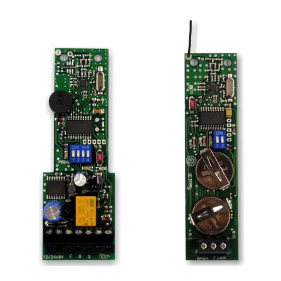
1- Terminals
2- Battery1 CR2032
3- Battery 2 CR2032
4- LED
5- DIP - Switch
6- Push button
7- Antenna
TECHNICAL SPECIFICATIONS
Receiver suply voltatge
12/24 AC/DC
Transmitter suply voltatge
2x lithium battery 3V DC type CR2032
Receiver memory
14 transmitters
Receiver Output
Relay,micro disconnection 1B
Receiver Power consumption
0.5 W - 12 V / 1,2 W - 24 V
Ball pressure test (IEC 695-10-2)
PCB (125ºC) WRAP (75ºC)
Pollution degree
2
Protection class (IEC 60529)
Ip67
Frecuency Channels
868.95MHz & 869.85MHz
Range
100m
Working temperature
-35ºC to +55ºC
Software
Class A
Rated transient over voltage
330V
Transmitter power consumption
Transmitting 17mA / stand by 16uA
EN 13849-2:2008 PL-C Category 2
Machine Security Normative
Instruction Manual
GENERAL (TRANSMITTER)
RECEIVER
Radio transmission system for resistive safety edges. The system consists of a transmitter unit and a receiver unit.
7
Important:
- Insert battery 1 first and then battery 2! Unless this order is observed, correct function is not guaranteed. The batteries must be suitable for use at
temperatures of -20°C and above
- The system has no fuse protection. It is advisable to include a fuse protection of minimum 100mA and maximum 250mA into the external Power.
6
4
5
3
START-UP
2
WirelessBand transmitter and receiver must be mounted on separate surfaces.
1.- Insert the enclosed batteries into the transmitter (type CR2032). Important: insert battery 1 first and then battery 2! Unless this order is observed,
correct function is not guaranteed.
2.- Connect receiver to supply voltage. (Note correct polarity for DC.)
3.- Check switch settings.
4.- Carry out programming steps. Transmitter and receiver are now matched to one another.
5.- Install transmitter on gate.
6.- Wire safety edge to transmitter.
7.- Install receiver at designated location.
1- Terminals
8.- Wire supply voltage, test input and output to control unit.
2- LED 1
9.- Switch on voltage.
3- Push button
10.- Carry out test by actuating the connected safety edge in different gate positions, particularly the open and closed positions.
4- DIP - Switch
11.- We recommend carrying out steps 1 to 4 prior to installing the device. A minimum distance of 1m must be observed between the transmitter and
5- LED 2
Receiver.
6- Buzzer
7- Antenna
TRANSMITTER OPTION SELECTOR
OPTION 1 - SAFETY EDGE TYPE
ON
OFF
OPTION 2 - TRANSMITTER FRECUENCY
ON
OFF
( WIRELESSBAND 1.0 )
Resistive safety edge
Contact safety edge
Frequency 869,85 MHz, setting MUST match that of receiver
Frequency 868,95 MHz, setting MUST match that of receiver
Advertisement

Related Manuals for AERF WIRELESSBAND 1.0


Summary of Contents for AERF WIRELESSBAND 1.0
- Page 1 Instruction Manual ( WIRELESSBAND 1.0 ) GENERAL (TRANSMITTER) TRANSMITTER TRANSMITTER RECEIVER Radio transmission system for resistive safety edges. The system consists of a transmitter unit and a receiver unit. Important: - Insert battery 1 first and then battery 2! Unless this order is observed, correct function is not guaranteed. The batteries must be suitable for use at temperatures of -20°C and above...
- Page 2 Instruction Manual ( WIRELESSBAND 1.0 ) GENERAL (RECEIVER) RECEIVER OPTION SELECTOR Important: OPTION 1 - CLASS 2 - To replace transmitter battery and safety of the power supply insert battery 1 first and then battery 2! Unless this order is observed, correct Class 2 enabled.
Need help?
Do you have a question about the WIRELESSBAND 1.0 and is the answer not in the manual?
Questions and answers