
Subscribe to Our Youtube Channel
Related Manuals for Amcrest AMPS5E4P-AT-65


Summary of Contents for Amcrest AMPS5E4P-AT-65
- Page 1 Simple. Reliable. Secure. AMPS5E4P-AT-65 AMPS9E8P-AT-96 4/8-Port PoE Switch User’s Manual Version 1.0.3...
- Page 2 This manual is for reference only. All the designs and software here are subject to change without prior written notice. All trademarks and registered trademarks are the properties of Amcrest Technologies LLC. Applicable Models: The manual can be applied to the following models:...
-
Page 3: Table Of Contents
Table of Contents Product Overview Features Typical Application Device Structure 4-Port PoE Switch 2.1.1 Front Panel 2.1.2 Back Panel 2.1.3 PoE Power Output 8-Port PoE Switch 2.2.1 Front Panel 2.2.2 Back Panel 2.2.3 PoE Power Output Appendix 1 Technical Specification... -
Page 4: Product Overview
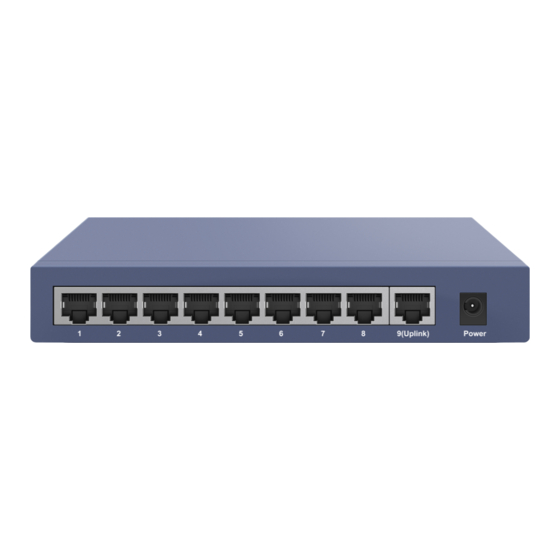
8-port PoE switch supports 1 10/100M self-adaptive RJ45 UpLink port and 8 10/100M self-adaptive PoE RJ45 ports. 8-port PoE switch with max 96W total power consumption. Typical Application The typical application of the device is shown in Figure 1- 1 Camera RJ45 Cable Camera Amcrest 4/8 Port PoE Switch Switch Camera Wi-Fi AP Figure 1.1... -
Page 5: Device Structure
Device Structure 4-Port PoE Switch 2.1.1 Front Panel The front panel is shown in Figure 2-1. Figure 2.1 Name Note Ethernet Ports 4 10/100M self-adaptive RJ45 PoE ports. 1 UpLink Port. Sheet 2-1 2.1.2 Back Panel The back panel is shown in Figure 2-2. Figure 2.2... -
Page 6: Poe Power Output
Name Note Power/PoE Max Indicates the switch is powered on and if the maximum PoE power available is used. Ground Used as grounding option for the switch. Power connection port. Supports 52V 1.25A Sheet 2-2 2.1.3 PoE Power Output 10/100M RJ45 PoE Ports support IEEE802.3af and IEEE802.3at power standards. Supports simultaneous power to 2 ports using IEEE802.3t and 4 ports using IEEE802.3af. -
Page 7: Back Panel
2.2.2 Back Panel The back panel is shown in Figure 2-4. Figure 2.4 Name Note Indicates the switch is powered on. 9(Uplink) Port Status LED. Blinking – data transmitting. Solid – link established. Off – no connection. 1, 2, 3, 4, 5, 6, 7, 8 Port Status LEDs. -
Page 8: Appendix 1 Technical Specification
Appendix 1 Technical Specification TECHNICAL PARAMETERS AMPS5E4P-AT-65 AMPS9E8P-AT-96 Physical Port Network Ports 1*10/100 Base-T (UpLink) 1*10/100 Base-T (UpLink) 4*10/100 Base-T (POE powered) 8*10/100 Base-T (POE powered) Technical Index Exchange Capacity 1.0Gbps 1.8Gbps Packet Forwarding Rate 0.74Mpps 1.34Mpps Exchange Mode Store & forward... - Page 9 Learn more at www.amcrest.com 2019 © Amcrest Technologies . All rights reserved. 16727 Park Row Houston, TX 77084-5020 Phone: +1 888 212 7538...
Need help?
Do you have a question about the AMPS5E4P-AT-65 and is the answer not in the manual?
Questions and answers