Advertisement
Quick Links
INSTALLAZIONE – INSTALLATION – MONTAGE – EINBAU
MISCELATORE TERMOSTATICO INCASSO CON DEVIATORE DA 2 A 6 VIE
CONCEALED THERMOSTATIC MIXER WITH FROM 2 TO 6 WAYS DIVERTER
MELANGEUR THERMOSTATIQUE A ENCASTRER AVEC DEVIATEUR DE 2 A 6 VOIES
TEIL BUILT THERMOSTAT-MISCHER MIT VON 2 BIS 6 WEGE-UMSTELLUNG
Advertisement

Related Manuals for Calflex Carimali 21820-CR


Summary of Contents for Calflex Carimali 21820-CR
- Page 1 INSTALLAZIONE – INSTALLATION – MONTAGE – EINBAU MISCELATORE TERMOSTATICO INCASSO CON DEVIATORE DA 2 A 6 VIE CONCEALED THERMOSTATIC MIXER WITH FROM 2 TO 6 WAYS DIVERTER MELANGEUR THERMOSTATIQUE A ENCASTRER AVEC DEVIATEUR DE 2 A 6 VOIES TEIL BUILT THERMOSTAT-MISCHER MIT VON 2 BIS 6 WEGE-UMSTELLUNG...
- Page 2 TERMOSTATICO ORIZZONTALE CON DEVIATORE A TERMOSTATICO ORIZZONTALE CON DEVIATORE A 4 O 5 O 6 2 O 3 VIE E SUPPORTO DOCCIA VIE E SUPPORTO DOCCIA HORIZONTAL THERMOSTATIC WITH 2 OR 3 WAYS HORIZONTAL THERMOSTATIC WITH 4 OR 5 OR 6 WAYS DIVERTER AND SHOWER HOLDER DIVERTER AND SHOWER HOLDER THERMOSTATIQUE HORIZONTAL AVEC DEVIATEUR...
-
Page 3: Informazioni Preliminari
INFORMAZIONI PRELIMINARI I miscelatori termostatici della linea CARIMALI sono idonei al funzionamento con acqua calda fornita da accumulatori in pressione. Per il funzionamento con scalda acqua istantanei elettrici o a gas verificare che questi abbiano una potenza non inferiore a 18 KW o 250 Kcal/min;... -
Page 4: Informations Preliminaires
INFORMATIONS PRELIMINAIRES Les mixers thermostatiques de la ligne CARIMALI adaptés à fonctionner avec l’eau chaude fournie par accumulateurs en pression. Pour le fonctionnement avec chauffe-eau instantanés électriques ou à gaz, vérifier que ceux-ci aient une puissance non inférieure à 18 KW ou 250 Kcal/min. ; pour le type à gaz il est recommandé l’usage d’appareillage avec réglage de la flamme en fonction du volume d’eau prélevé. - Page 5 2-3 vie / 2-3 ways / 2-3 voies / 2-3 Wege 4-5-6 vie / 4-5-6 ways / 4-5-6 voies / 4-5-6 Wege quadro / square / carré / platz quadro / square / carré / platz senza supporto doccia con supporto doccia con supporto doccia senza supporto doccia without shower holder...
- Page 6 2-3 vie / 2-3 ways / 2-3 voies / 2-3 Wege 4-5-6 vie / 4-5-6 ways / 4-5-6 voies / 4-5-6 Wege tondo / round / rond / runden tondo / round / rond / runden senza supporto con supporto doccia doccia con supporto doccia senza supporto doccia...
- Page 7 2-3 vie / 2-3 ways / 2-3 voies / 2-3 Wege 4-5-6 vie / 4-5-6 ways / 4-5-6 voies / 4-5-6 Wege Colonial / Colonial / Colonial / Colonial Colonial / Colonial / Colonial / Colonial senza supporto doccia senza supporto doccia without shower holder without shower holder sans support de douche...
- Page 8 Art. 21820-CR; Art. 21830-CR Art. 21840-CR; Art. 21850-CR; Art. 21860-CR Art. 21829/A-CR; Art. 21839/A-CR Art. 21849/A-CR; Art. 21859/A-CR; Art. 21869/A-CR Preparare un foro adeguato nella parete: le quote di installazione sono riportate nella figura (la profondità di incasso ammissibile è intesa a parete finita compreso il rivestimento). Make an appropriate hole in the wall: installation rates are indicated in the picture (allowed built-in depth means at finished wall level surface including coating).
- Page 9 Art. 21221/O-CR; Art. 21231/O-CR; Art. 21241/O-CR; Art. 21251/O-CR; Art. 21261/O-CR; Art. 21221-CR; Art. 21231-CR Art. 21241-CR; Art. 21251-CR; Art. 21261-CR Art. 21225/O-CR; Art. 21235/O-CR; Art. 21245/O-CR; Art. 21255/O-CR; Art. 21265/O-CR; Art. 21225-CR; Art. 21235-CR Art. 21245-CR; Art. 21255-CR; Art. 21265-CR Art.
- Page 10 TERMOSTATICO ORIZZONTALE CON DOCCIA INCORPORATA HORIZONTAL THERMOSTATIC MIXER WITH INTEGRATED HAND SHOWER MÉLANGEUR THERMOSTATIQUE HORIZONTAL AVEC DOUCHETTE INTÉGRÉE ORIZONTAL THERMOSTAT-MISCHER MIT INTEGRIERTER HANDDUSCHE Inserire nel foro sulla parete il gruppo incasso (A) con le protezioni montate, collegare le mandate delle acque (acqua fredda a destra, acqua calda a sinistra) ed eseguire l’impianto idraulico.
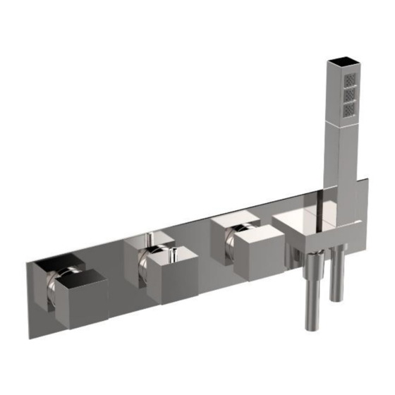
- Page 11 2 VIE CON SUPPORTO Art. 21820-CR Art. 21829/A-CR 2 WAYS W/ SHOWER HOLDER 3 VIE CON SUPPORTO Art. 21830-CR Art. 21839/A-CR 3 WAYS W/ SHOWER HOLDER 4 VIE CON SUPPORTO Art. 21840-CR Art. 21849/A-CR 4 WAYS W/ SHOWER HOLDER 5 VIE CON SUPPORTO Art.
- Page 12 TERMOSTATICO ORIZZONTALE SENZA DOCCIA INCORPORATA HORIZONTAL THERMOSTATIC MIXER WITHOUT INTEGRATED HAND SHOWER MÉLANGEUR THERMOSTATIQUE HORIZONTAL SANS DOUCHETTE INTÉGRÉE ORIZONTAL THERMOSTAT-MISCHER OHNE INTEGRIERTER HANDDUSCHE Inserire nel foro sulla parete il gruppo incasso (A) con le protezioni montate, collegare le mandate delle acque (acqua fredda a destra, acqua calda a sinistra) ed eseguire l’impianto idraulico.
- Page 13 Art. 21221O-CR 2 VIE ORIZZONTALE Art. 21225O-CR 2 WAYS HORIZONTAL Art. 21228/AO-CR Art. 21231O-CR 3 VIE ORIZZONTALE Art. 21235O-CR 3 WAYS HORIZONTAL Art. 21238/AO-CR Art. 21241O-CR 4 VIE ORIZZONTALE Art. 21245O-CR 4 WAYS HORIZONTAL Art. 21248/AO-CR Art. 21251O-CR 5 VIE ORIZZONTALE Art.
- Page 14 TERMOSTATICO VERTICALE SENZA DOCCIA INCORPORATA Inserire nel foro sulla parete il gruppo incasso (A) con le protezioni montate, collegare le mandate delle acque (acqua fredda a destra, acqua calda a sinistra) ed eseguire l’impianto idraulico. ATTENZIONE: collegare le utenze seguendo la numerazione dello schema (il tubo “1” deve essere la mandata dell’acqua dell’utenza indicata dal punto “1”...
- Page 15 Art. 21221-CR Art. 21251-CR 2 VIE VERTICALE 5 VIE VERTICALE Art. 21225-CR Art. 21255-CR 2 WAYS VERTICAL 5 WAYS VERTICAL Art. 21228/A-CR Art. 21258/A-CR Art. 21231-CR Art. 21261-CR 3 VIE VERTICALE 6 VIE VERTICALE Art. 21235-CR Art. 21265-CR 3 WAYS VERTICAL 6 WAYS VERTICAL Art.
- Page 16 Dopo avere effettuato tutti i collegamenti mettere in bolla il gruppo incasso (A). After operating all connections, put the built-in group (A) in the correct bubble position with a level. Après avoir fait tous les raccords mettre le groupe encastré (A) à niveau à l’aide d’un niveau à bulle. Setzen der eingebauten Gruppe (A) in der richtigen blasen Lage.
- Page 17 Inserire la manopola (R) per il collaudo dell’impianto con la leva rivolta verso l’indicatore a freccia (CLOSE), come mostrato in figura. Insert the handle (R) to test the plumbing system with the rod facing the indicator with the arrow (CLOSE) as shown in the pirctures here above.
- Page 18 Collaudare l’impianto (pressione massima di prova 16 bar) nel modo indicato di seguito, in base al tipo di deviatore. Eseguire il collaudo in base alla sequenza numerata indicata. Test the system (16 bar maximum test pressure) as shown here below according to the diverter type. Test the system according to the numeric sequence as indicated.
- Page 21 Rifinire l’intonaco e applicare il rivestimento. IMPORTANTE: La profondità di incasso ammissibile è indicata anche sulle protezioni. Finish the plaster and put the coating. IMPORTANT: The allowed built-in depth is also indicated on the protections. Refinir le plâtrage et appliquer le revêtement. IMPORTANT : La profondeur d’encastrement admise est indiquée aussi sur les protections.
- Page 22 A rivestimento ultimato rimuovere le piastre di fissaggio svitando i dadi con chiave inglese da 7 mm e i tiranti filettati. When the coating is over, remove the fixing plates by unscrewing the nuts with a 7 mm wrench and by removing threaded tie rods.
- Page 23 SOLO PER VERSIONE CON SUPPORTO ONLY FOR VERSION WITH SHOWER HOLDER UNIQUEMENT POUR VERSION AVEC SUPPORT DE DOUCHE NUR FÜR VERSION MIT DUSCHHALTER Avvitare il raccordo (B) al corpo incasso (A) con chiave a brugola da 6 mm, utilizzando canapa o similari per realizzare la tenuta idraulica.
- Page 24 ATTENZIONE: prima di procedere con l’installazione verificare che la ghiera di limitazione della temperatura abbia l’indicatore (I) rivolto verso l’alto. WARNING: before proceeding with the installation, verify that the adjusting temperature ring has the indicator (l) facing up. ATTENTION : avant de procéder à l’installation, vérifier que la bague de limitation de température a l’indicateur (l) tourné...
- Page 25 Avvitare ed inserire a mano le ghiere (C) e (D). Inserire la piastra (E) aggiungendo del silicone sul retro in modo da farla aderire alle piastrelle per evitare infiltrazioni di acqua all’ interno del muro. Insert and hand-tighten the nuts (C) and (D). Insert the plate (E) by siliconizing the back of it to make the plate stick and avoid water infiltrations in the wall.
- Page 26 Versioni quadre e tonde Round and square versions Versions rondes et carrées Rund- und Quadrat-Versionen Montare le prolunghe (F) e (G) sulle aste delle cartucce e bloccarle tramite le viti (H) e (I) con chiave a brugola da 2,5 mm. Inserire le manopole (L) e (M) e bloccarle serrando i grani (N) con chiave a brugola da 2,5 mm.
- Page 27 Versioni antiche Traditional versions Versions traditionnelles Traditionellen Versionen Montare le prolunghe (F) sulle aste delle cartucce. Inserire le maniglie (L), (M) e (N) e bloccarle serrando le viti (H) e (I) con chiave a brugola da 3 mm, interponendo la rondella (O). Avvitare le placchette (P). ATTENZIONE: per la posizione corretta delle maniglie (L) e (M) verificare tabella seguente.
- Page 28 Art. 21820-CR Art. 21829/A-CR Art. 21221O-CR 2 VIE Art. 21225O-CR 2 WAYS 2 VOIES Art. 21228/AO-CR 2 WEGE Art. 21221-CR Art. 21225-CR Art. 21228/A-CR Art. 21830-CR Art. 21839/A-CR Art. 21231O-CR 3 VIE Art. 21235O-CR 3 WAYS 3 VOIES Art. 21238/AO-CR 3 WEGE Art.
- Page 29 USO E MANUTENZIONE: Funzionamento USE AND MAINTENANCE: Functioning 4 VIE / 4 WAYS / 4 VOIES / 4 WEGE UTILISATION ET ENTRETIEN: Fonctionnement VERWENDUNG UND WARTUNG: Lauf 2 VIE / 2 WAYS / 2 VOIES / 2 WEGE 5 VIE / 5 WAYS / 5 VOIES / 5 WEGE 3 VIE / 3 WAYS / 3 VOIES / 3 WEGE 6 VIE / 6 WAYS / 6 VOIES / 6 WEGE La manopola [1] regola la temperatura dell’acqua miscelata (senso antiorario=calda / senso orario=fredda).
- Page 30 USO E MANUTENZIONE: Smontaggio valvole di non ritorno USE AND MAINTENANCE: Non-return valves disassembly UTILISATION ET ENTRETIEN: Démontage des clapets anti-retour VERWENDUNG UND WARTUNG: Ausbau nicht-Rücklauf Ventil Versioni quadre e tonde Round and square versions Versions rondes et carrées Rund- und Quadrat-Versionen Rimuovere le placchette (O).
- Page 31 Versioni antiche Traditional versions Versions traditionnelles Traditionellen Versionen Montare le prolunghe (F) e (G) sulle aste delle cartucce. Inserire le maniglie (L), (M) e (N) e bloccarle serrando le viti (H) e (I) con chiave a brugola da 3 mm. Avvitare le placchette (O). ATTENZIONE: per la posizione corretta delle maniglie (L) e (M) verificare tabella di pagina 28.
- Page 32 Chiudere gli ingressi dell’acqua fredda e dell’acqua calda. Svitare la valvola utilizzando una chiave a brugola da 12 mm. Pulire o sostituire la valvola (WRAC0178). Riavvitare la valvola sul termostatico utilizzando una chiave a brugola da 12 mm fino in battuta. Close both the inlets of cold and hot water.
- Page 33 ATTENZIONE: prima di procedere con l’installazione verificare che la ghiera di limitazione della temperatura abbia l’indicatore (I) rivolto verso l’alto. WARNING: before proceeding with the installation, verify that the adjusting temperature ring has the indicator (l) facing up. ATTENTION : avant de procéder à l’installation, vérifier que la bague de limitation de température a l’indicateur (l) tourné...
- Page 34 Inserire la piastra (E) aggiungendo del silicone sul retro in modo da farla aderire alle piastrelle per evitare infiltrazioni di acqua all’ interno del muro. Insert the plate (E) by siliconizing the back of it to make the plate stick and avoid water infiltrations in the wall. Insérer la plaque (E) en mettant du silicone sur la face arrière pour la coller et éviter infiltrations d’eau dans la paroi.
- Page 35 Versioni quadre e tonde Round and square versions Versions rondes et carrées Rund- und Quadrat-Versionen Inserire le manopole (L) e (M) e bloccarle serrando i grani (N) con chiave a brugola da 2,5 mm. Inserire le placchette (O). ATTENZIONE: per la posizione corretta delle manopole (L) e (M) verificare tabella di pagina 28. Insert the handles (L) and (M) and block them by tightening the nuts (N) with a 2.5 mm Allen wrench.
- Page 36 Versioni antiche Traditional versions Versions traditionnelles Traditionellen Versionen Montare le prolunghe (F) e (G) sulle aste delle cartucce. Inserire le maniglie (L), (M) e (N) e bloccarle serrando le viti (H) e (I) con chiave a brugola da 3 mm, interponendo la rondella (O). Avvitare le placchette (O). ATTENZIONE: per la posizione corretta delle maniglie (L) e (M) verificare tabella di pagina 28.
- Page 37 USO E MANUTENZIONE: Smontaggio cartuccia termostatica e/o deviatrice per pulizia o sostituzione USE AND MAINTENANCE: Removal of the thermostatic and/or deviator cartridge for cleaning or replacement UTILISATION ET ENTRETIEN: Démontage de la cartouche thermostatique et/ou d’inversion pour le nettoyage ou le remplacement VERWENDUNG UND WARTUNG: Ausbau Thermostatische oder Mischer-Kartusche zum Reinigen oder Austauschen Versioni quadre...
- Page 38 Versioni antiche Traditional versions Versions traditionnelles Traditionellen Versionen Svitare le placchette (O). Svitare le viti (H) e (I) con chiave a brugola da 3 mm e sfilare le manopole (L), (M) e (N) e le prolunghe (F) e (G). Sfilare la piastra (E). Remove the small plates (O).
- Page 39 SMONTAGGIO CARTUCCIA TERMOSTATICA Chiudere gli ingressi dell’acqua fredda e dell’acqua calda. Sfilare la ghiera di limitazione della temperatura (3). Svitare la ghiera (2) con chiave da 32 mm. Sfilare la cartuccia termostatica (1). Pulire o sostituire la cartuccia. In caso di sostituzione svitare la vite (5) con chiave a brugola da 2,5 mm, sfilare la prolunga (4) dalla cartuccia vecchia.
- Page 40 Per una politica di continuo miglioramento, CALFLEX S.r.l. si riserva la possibilità di applicare modifiche tecniche sui suoi articoli senza nessun preavviso. For a continuous improvement policy, CALFLEX S.r.l. reserves the right to modify the technical features of its articles at any time without notice.
Need help?
Do you have a question about the Carimali 21820-CR and is the answer not in the manual?
Questions and answers