Table of Contents
Advertisement
Quick Links
Advertisement
Table of Contents

Related Manuals for Perfect Prime TC2100


Summary of Contents for Perfect Prime TC2100
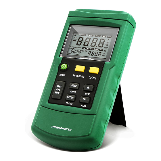
- Page 1 Digital Thermometer TC2100 Instruction Manual...
-
Page 2: Table Of Contents
CONTENTS 1. Safety Information ..............2 - 3 2. Product Overview ..............4 3. Meter Description ..............5 - 8 3.1 Component ....................5 3.2 Display ......................6 3.3 Keys Description ................7 - 8 4. Setting Meter ..............9 - 12 4.1 SETUP Option .................. -
Page 3: Safety Information
1.SAFETY INFORMATION In order to use the thermometer safely and correctly, please read this manual carefully rst, especially the “Safety Information” part. It is recommended to keep the manual at hand so that one can refer to it at any time. Warning Warning indicates a situation/action which may cause danger to users. - Page 4 1.SAFETY INFORMATION Caution Situations/actions which may cause damage to the meter are listed below. To prevent damage, use the meter carefully. Select appropriate thermocouple probes, function grade and measuring range before using. Ensure there is no di erence between two lines when using dual-line measurement.
-
Page 5: Product Overview
2. PRODUCT OVERVIEW This product includes thermocouple probes with microprocessor as the temperature sensor. It has the following features: • Suitable for various thermocouples probes: K, J, T,E, R, S, N • Di erent temperature units: °C, °F and K (Kelvin) •... -
Page 6: Meter Description
3. METER DESCRIPTION 3.1 Components OFFSE T SETUP RE AD HOLD T1 T2 °F T1-T2 °C TYPE KJTER SN INTERV AL hour:min °F T1 T2 °C min:sec POWER - T1 + - T2 + HOLD SETUP THERMOMETER USB port Measure under normal temperature Thermocouple probe T1 input Display Thermocouple probe T2 input... -
Page 7: Display
3. METER DESCRIPTION 3.2 Display Automatic power-off indicator MAX, MIN, AVGt Low battery indicator: Battery Indicator to save data should be replaced. Auxiliary display unit Thermocouple measurements Auxiliary display include deviation value USB port Status setup indicator with flashing display Time display Indicator to display saved data Indicate time display min: sec... -
Page 8: Keys Description
3. METER DESCRIPTION 3.3 Keys Description POWER Power on/o thermometer Select to display T1, T2 and T1-T2 T1/T2/ (temperature di erence measurement) on T1-T2 main/auxiliary screen Unit selection: Celsius (°C), ˚C/˚F/K Fahrenheit (°F), Kelvin (K) View maximum, minimum and average MAX/MIN value. - Page 9 3. METER DESCRIPTION POWER Power on/o thermometer Press and hold to open USB, press and hold PC-Link again to turn o To change setting options/add ▲ functions, see speci c operation for details To change setting options/reduce ▼ functions, see speci c operation for details Read saved data READ Save current data...
-
Page 10: Setting Meter
4. SETTING METER 4.1 SETUP Option Press the SETUP key to enter setup mode. → “ SETUP ” symbol will ash on the screen. Press again to switch setting states. Save all previous settings before exiting. → If the meter is turned o in the process of saving settings, changes will not be saved. - Page 11 4. SETTING METER OFFSET (T1) setting: Users can adjust the thermometer displayed value to compensate for the thermocouple probe error. See “Adjust the temperature sensor error with deviation value” section. Allowable adjustment range is ±6°C. After entering OFFSET (T1) setting state, the o set value setting can be changed with ▲...
- Page 12 4. SETTING METER Automatic power-o time setting (P): Enter the automatic power-o time setting mode. → “P-” will show on the screen Set automatic power-o time (5 to 60 minutes) with ▲ ▼. Set the sleep time <5 minutes to show “OFF”. →...
- Page 13 4. SETTING METER Normal temperature compensation (NTC): Enter normal temperature compensation (NTC) switch setting mode. → “NTC” will show on the screen. ON/OFF can be set for normal temperature compensation with ▲▼. Meter automatically restores to ON state after reboot. Auto-calibration switch setting (CAL): Enter the ON/OFF setting of auto-calibration (CAL).
-
Page 14: Using The Meter
5. USING THE METER 5.1 Connecting Thermocouple probe Insert the thermocouple probe to input jack. Press the power key to turn on the meter. Set the thermocouple probe type to be consistent with the inserted thermocouple probe type. Note: If the thermocouple probe is not connected to the selected input end/the thermocouple probe is “open”/ exceeds measuring range, “OL”... -
Page 15: Use O Set Value To Adjust
5. USING THE METER 5.5 Use o set Value ToAdjust Temperature Probe Error Use OFFSET (T1) & (T2) in the Setup to adjust the meter readings to compensate for thermocouple probe error. Put the thermocouple probe in a known and stable temperature environment (such as in ice bath or dry well calibrator). - Page 16 5. USING THE METER Press “ENTER” to save current calibration value. Press “T1/T2/T1-T2” / “TC TYPE” key to switch to T1 measurement channel. Input 0 V in T1 measurement channel. After stabilizing, press “ENTER” to save current calibration value. Input 40.000mV in T1 measurement channel. After stabilizing, press “ENTER”...
-
Page 17: Data Storage
6. DATA STORAGE 6.1 Data Storage Manual storage is in the normal measurement mode and data storage interval (INTERVAL) is set to 00:00. Press the “MEM” key to store an item of data. Storage location will be the smallest no. in the unused storage space. If storage space is full of data, “FULL”... -
Page 18: Clearing Stored Data
6. DATA STORAGE 6.3 Clearing Stored Data Please refer to Data clearing (CLr) in 4.2 SETUP Option Setting. Data Transmission Connect the thermometer to PC with data line. Hold “PCLink” key. → “ USB ” symbol will show on screen. →... -
Page 19: Meter Maintenance
7. METER MAINTENANCE 7.1 Replace Battery • Turn o the power. • Unscrew the screw and remove the cover. • Replace with 9V battery. • Put battery cover back and tighten the screw. 7.2 Clean Use a soft cloth/sponge to wipe the product surface gently with a little soap water or detergent. -
Page 20: Technique Data
8.TECHNICAL DATA The indicator is accurate within the temp. range (18°C-28°C) and relative humidity is <80%. Warranty period is one year (thermocouple probe error not included). Function The meter K, J, T, E, R, S, N Thermocouple probe type T1/T2 Measurement channel K: -200.0°C to +1372°C... - Page 21 8.TECHNICAL DATA Function The meter <-10°C: within +0.5°C ; <-200°C: within +1°C T-type < -200°C for reference only Relative time Time Data record 0~999, 1000 groups in total ITS-90 Temperature scale Applicable NIST-175 standard Setting Recording interval setting*, functions thermocouple type setting, thermocouple probe o set setting, automatic power-o time setting, system time setting, power frequency...
- Page 22 CUSTOMER SERVICE INQUIRIES Your emails are important to us so we strive to reply all hours. In exceptional cases, inquiries and emails within we may require more time to respond. Thank you for your understanding. For more information about our products and services, please send us an email: cs@perfectprime.com For B2B or project-based application, please send an email:...
- Page 23 HORMES LIMITED Retailer cs@perfectprime.com Email G/F UNIT 3, 61 GLENTHORNE ROAD, Address LONDON W6 0LJ UNITED KINGDOM +44 203 7695377 Telephone...
Need help?
Do you have a question about the TC2100 and is the answer not in the manual?
Questions and answers