Sign In
Upload
Download
Table of Contents
Contents
Add to my manuals
Delete from my manuals
Share
URL of this page:
HTML Link:
Bookmark this page
Add
Manual will be automatically added to "My Manuals"
Print this page
×
Bookmark added
×
Added to my manuals
Manuals
Brands
Vacon Manuals
Computer Hardware
optc3
User manual
Vacon OPTC3 User Manual
Profibus dp option board
Hide thumbs
Also See for OPTC3
:
User manual
(47 pages)
1
Table Of Contents
2
3
4
5
6
7
8
9
10
11
12
13
14
15
16
17
18
19
20
21
22
23
24
25
26
27
28
29
30
31
32
33
34
35
36
37
38
39
40
41
42
page
of
42
Go
/
42
Contents
Table of Contents
Bookmarks
Table of Contents
Table of Contents
1 General
2 Profibus Dp Option Board Technical Data
General
Profibus Cable
3 Profibus Dp
Introduction
Profiles
Variable Speed Drive Profile (3.071)
4 Profibus Fieldbus Board Layout and Connections
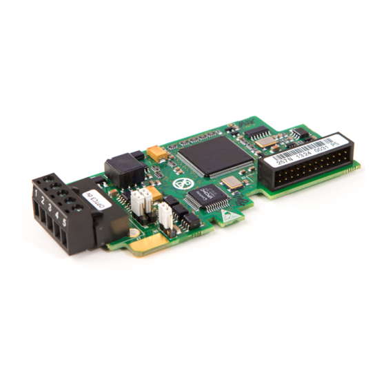
Profibus OPT-C3 Option Board
Grounding of Bus Cable Shield in OPT-C3
Profibus OPT-C5 Option Board
Grounding of a D-Connector
Bus Terminal Resistors
LED Indications
5 Installation of Vacon Nx Profibus Board
6 Commissioning
Fieldbus Board Parameters
Start-Up Test
7 Profibus-Vacon Nx Interface
General
Operation Mode
PPO Types
Process Data
Control Word
Status Word
State Machine
Reference 1
Actual Value 1
Pd1
Parameter Data
Parameter Field
Example Messages
8 Fault Tracking
9 Type Files
GSD-File ("Profibus Support Disk" Files: Vac29500.Gsd, Vac29500.Gse)
10 Appendix
Advertisement
Quick Links
1
Profibus Dp Option Board Technical Data
2
Profibus Opt-C3 Option Board
3
Profibus Opt-C5 Option Board
4
Gsd-File ("Profibus Support Disk" Files: Vac29500.Gsd, Vac29500.Gse)
Download this manual
vacon nx
ac drives
optc3/c5
profibus dp option board
user manual
Table of
Contents
Previous
Page
Next
Page
1
2
3
4
5
Advertisement
Table of Contents
Need help?
Do you have a question about the OPTC3 and is the answer not in the manual?
Ask a question
Questions and answers
Related Manuals for Vacon OPTC3
Controller Vacon optc3 User Manual
Profibus dp option board (47 pages)
Computer Hardware Vacon CANopen OPTE6 User Manual
Option board (103 pages)
Computer Hardware Vacon OPTC5 User Manual
Profibus dp option board (42 pages)
Computer Hardware Vacon NX OPTC3 User Manual
Profibus dp option board (46 pages)
Computer Hardware Vacon CX Installation Manual
Frequency converters i/o-expander board (17 pages)
This manual is also suitable for:
Optc5
Table of Contents
Print
Rename the bookmark
Delete bookmark?
Delete from my manuals?
Login
Sign In
OR
Sign in with Facebook
Sign in with Google
Upload manual
Upload from disk
Upload from URL


Need help?
Do you have a question about the OPTC3 and is the answer not in the manual?
Questions and answers