
Related Manuals for Shire Command post


Summary of Contents for Shire Command post
- Page 1 © Command post Complies with EN71 These instructions are for your safety. Please read through them thoroughly before use . PLEASE KEEP THIS LEAFLET FOR FUTURE REFERENCE...
-
Page 2: Table Of Contents
Let’s get started... Important information... Safety Base and positioning Warranty Care maintenance & Recycling In more detail... Hardware Chart & Fascia bag 06-07 Stacked Parts List Detailed Technical Drawings 10-13 Before you start Assembly instructions 15-32 For a copy of the instructions or a copy in another language please send an email or write to the address below. -
Page 3: Safety
Safety Check that you have noted all the following instructions We advise the use of non slip protective gloves throughout the assembly process. We advise the use of steel capped protective footwear throughout the assembly process We advise the use of protective headwear and safety goggles throughout the assembly process Where a ladder is in use another person must hold the ladder. -
Page 4: Base And Positioning
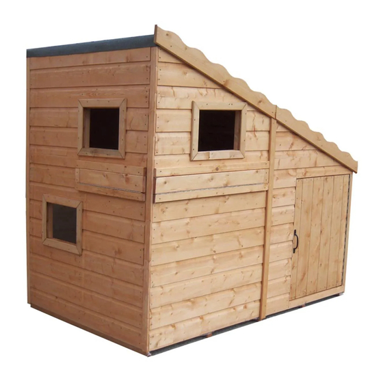
Base and Warranty Preparation of base... We recommend that the base onto which your building will stand should be at least 75mm larger in each direction than the total floor size of the building. Actual floor area of the building: 1790mm x 1190mm Total height clearance: 1680mm See drawing on front cover The chosen position in your garden for your building should be excavated to a depth of 75mm to allow a base of sand, on to which paving slabs can be evenly laid. -
Page 5: Care Maintenance & Recycling
Care, Maintenance and Recycling The 5 golden rules of care Ensure your base is level and firm Ensure the building is not sitting directly on the ground using damp proof membrane or the optional timber base. Ensure every piece of timber and surface, especially that is hidden upon assembly is treated with a top quality wood preservative at least twice (see note on pressure treated buildings in warranty section). -
Page 6: Hardware Chart & Fascia Bag
Fascia & nail bag contents Hardware Chart Scale 1:1 8mmFelt Nail (A0266) x 98 40mmRound head nail (A0025) x 66 Note 12mm Flat head These 12mm screws Posi-drive screw With roller catch (A0027) x 12 Black 12mm Posi-drive screw (A0029) x 08 25mm Posi-drive screw (A0032) x 90 Black 25mm... - Page 7 Fascia & nail bag contents Safety vent Roller catch Black D handle 32mm continuous 32mm continuous Hinge 535mm Hinge 810mm( ( A0476 ) x02 (A0090) x03 (A0089) x03 (A0101) x01 A0102) x01 32mm 32mm 75mm continuous Sm view port surround View port spacer Fascia SM view port shutter...
-
Page 8: Stacked Parts List
Stacked parts list Description (part No ) qty Floor End panel Lg angle panel (A0085)x01 (A0556) x01 (A0565) x01 1790mm 1120mm 895mm Sm end panel Sm angle panel Door panel Door (A0566)x01 (A0564) x01 (A0086) x01 (A0087)x01 1120mm 586mm 895mm 895mm 1.4 Felt strips Lg front panel... - Page 9 Description (part No ) qty...
-
Page 10: Detailed Technical Drawings
Detailed Technical drawing Door & Lg front panels A0086 A0091 A0090 A0089 A0087 A0088 A0100 A0562 A0098 A0099 A0099 A0090 A0098 A0089 A0096 A0096 A0095 A0102 A0097... - Page 11 Building Photographs It will be greatly appreciated if you could forward images of your completed building to - sales@shiregb.co.uk.
- Page 12 Detailed Technical drawing End Panel A0100 A0099 A0556 A0098 A0098 A0099 A0094 A0089 A0093 A0090 A101 A0095 A0094 A0099 A0099 A0098 A0098 A0100...
- Page 13 Detailed Technical drawing Building A0577 A0576 A0576 A0576 A0576 A0577 A0567 A0567 A0577 A0476 A0569 A0569 A0566 A0568 A0567 A0570 A0570 A0565 A0564 A0562 A0086 A0571 A0571 A0556 A0566 A0085 A0476...
-
Page 14: Before You Start
Before you start Things to check before you start Ensure your base is ready– See page 3 Check all parts as listed in the parts lists Read the instructions fully before starting work Follow all the health and safety guidelines When you see the drill icon Only ever drill through the first piece of framework which will be a... -
Page 15: Assembly Instructions
Assembly These instr uctions are for your safety. Please read through them thoroughly before use . Treat all the parts before assembly –see page 5 GB-IE Attach the hinge on the outside long edge of the door using 6 screws into the door and 6 into the door panel Door panel (A0086) x01 Door... - Page 16 Fix the Door block "A0091" on top and flush with the edge of the door frame. Attach the receiving clip GB-IE to the door and then clip the roller catch to the receiver and screw the receiver to the door block. Step 08 34mm` Door block...
- Page 17 There are two view port assemblies one is bigger that the other. The biggest one goes on panel GB-IE “A0562” It is best to lay all the parts out (on the panels if you wish) before you start. SEE PAGES 10-12.
- Page 18 Match the continuous hinges to the view port shutters. Fix the shorter hinge with 10 screws and the longer one with 14 screws. 20mm LG view port shutter (A0096)x01 20mm SM view port shutter (A0093)x01 32mm x 535mm Continuous hinge (A0101)x01 32mm x 810mm Continuous hinge...
- Page 19 Align the view port surround level with the edge of the aperture. GB-IE Attach the long pieces with 3 screws each and 1 screw for the short piece 44mm Sm view port surround (A0094)x02 44mm view port spacer (A0095)x02 44mm view port surround (A0097)x02 End panel...
- Page 20 The view port shutters fit inside the surrounds fitted in step 05 and open outwards and downwards. Align the view port shutter level with the edge of the aperture so the loose edge of the hinge is against GB-IE the edge of the surround below then fix with 14 screws for the long hinge and 10 for the short one. Attach a “D”...
- Page 21 Fix the roller catch “A0090” receiving clip to the shutter then clip the roller catch to the receiver and GB-IE screw to the aperture framework Roller catch (A0090)X02 12mmScrew (A0027) x08 Step 13 Step 13...
- Page 22 Drill 3 holes through the thicker part (not where the step for the glazing to go is) of each of the “A0098” and 2 holes in each of the “A0099” window frame parts. GB-IE Remove the protective film from both sides of the plastic glazing. Align the plastic glazing and the window frame over the apertures and attach with 25mm screws.
- Page 23 Do not drill the small angled panels “A0086 &A0564” GB-IE Only drill 2 holes through the side of the framework on the back of the panels as shown below. Step 15 Step 15 Lg angle panel (A0565) x01 Sm end panel (A0566)x01...
- Page 24 Place the panels with the cladding overhanging the floor .Panel “A0565” is positioned into the corner GB-IE of the floor and push the “A0556” up to it, Attach using the holes just drilled. Step 16 (A0556)x01 Lg angle panel (A0565) x01 60mm Screws (A0035)x02...
- Page 25 continue adding the walls GB-IE sm angle panel (A0564) x01 Sm end panel (A0566)x01 60mm Screws (A0035)x04...
- Page 26 continue adding the walls GB-IE sm door panel (A0086) x01 Lg front panel (A0562)x01 60mm Screws (A0035)x04...
- Page 27 Align the roof panel “A0567” with the lower edge and the cladding and fix with 3 nails into each wall. GB-IE Position the roof bearer “A0568” half way under the edge of the roof panel that you have fitted , Drill a hole through the side panels at either end of the roof bearer and fix with 2x 80mm screws.
- Page 28 Continue adding the roof panels and another roof bearer as in the previous step. GB-IE Also nail 3x40mm into the roof bearer through the roof panel fitted previously, Roof panels (A0567) x02 34mm Roof bearers (A0568)x01 40mm Nails (A0025)x27 80mmScrew (A0036) x02...
- Page 29 It fit corner strips only not the coverstrios over the joins, GB-IE Hold in position level with the bottom of the cladding and mark and trim the top to suit. If necessary . Attach the cover strips to each corner with 3x 40mm nails each, A0569 A0569 44mm...
- Page 30 Start at the bottom overhanging the felt approximately 40mm down the 3 walls. Nail into the end wall at 100mm centres. Then gently tighten the felt and fix with 2 nails at the top. Overlap the next piece of felt by about 400mm and nail just above the overlap as before. Again tighten and fix at the top with 2 nails.
- Page 31 I Nail the fascia boards into position and carefully trim the excess felt . Position the cover strips “A0570” over the panel join and mark and trim to fit under the fascia boards. GB-IE Attach with 3x 40mm nails each. Fascia (A0576) x02 44mm...
- Page 32 GB-IE Fix the walls to the floor with 1x60mm screw per panel 60mmScrew (A0035) x06 Push the vents “A0476” into the holes. 1 in the back panel and 1 in the end panel GB-IE Safety vent (A0476) x02 customerservice@shiregb.co.uk Brigstock Road Wisbech Cambridgeshire PE13 3JJ...
Need help?
Do you have a question about the Command post and is the answer not in the manual?
Questions and answers