Advertisement
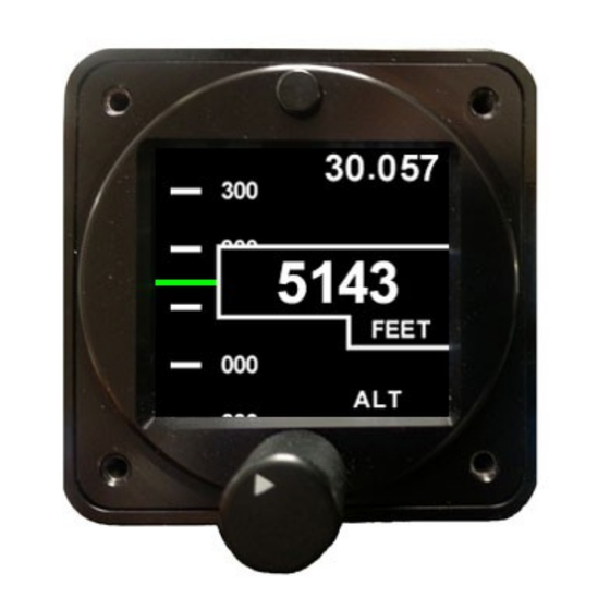
ALT200 Pressure Sensitive Altimeter
THIS IS A TRANSPORT CANADA APPROVED MANUAL
The following checklist outlines the required articles for the ALT200 altimeter.
Documentation
Introduction (this document)
Authorized Release Certificate
Components
ALT200 Instrument
4 X Mounting Screws
Aerospace Logic Inc.
Tel. 416-628-0725
www.aerospacelogic.com
Document Number
S200-ALT200-001
S200-AWS
S200-ALT200-INST
S200-ALT200-004
S200-ALT200-005
S200-ALT200-006
S200-ALT200-007
TCCA FORM ONE
Document # S200-ALT200-001
Rev 1.2 09/06/2018
Page 1 of 2
Advertisement
Table of Contents

Subscribe to Our Youtube Channel
Related Manuals for Aerospace Logic ALT200


Summary of Contents for Aerospace Logic ALT200
- Page 1 ALT200 Pressure Sensitive Altimeter THIS IS A TRANSPORT CANADA APPROVED MANUAL The following checklist outlines the required articles for the ALT200 altimeter. Documentation Document Number Introduction (this document) S200-ALT200-001 Warranty Statement S200-AWS Wiring and Installation Schematic S200-ALT200-INST Setup Guide S200-ALT200-004...
- Page 2 2. Certified Aircraft Note: ALT200 is TSO’d to C10b with additional testing as an electronic altimeter. As such, it may replace any existing TSO C10b altimeter that does not exceed 35,000’...
- Page 3 FULL refund LESS shipping costs. ALL RETURNS REQUIRE RETURN MATERIAL AUHORIZATIONS (RMA). WE DO NOT ACCEPT RETURNS WITHOUT RMA NUMBERS. CALL 416-628-0725 FOR AUTHORIZATION. Aerospace Logic Inc. Document # S200-AWS Tel. 416-6268-0725 Rev 1.6 22-DEC-2014 www.aerospacelogic.com...
- Page 4 Rev 02 Bus voltage for daylight operations. or later If the panel rheostat does not function as above then use Aerospace Logic Aircraft ground potentiometer Part # A200-POT and connect per TABLE 2 THERE ARE NO INSTRUCTIONS FOR CONTINUED AIRWORTHINESS APPLICABLE TO THIS PRODUCT...
- Page 5 All flight operations are to be performed in accordance with the specific instructions pertaining to your aircraft, including those provided by the aircraft manufacturer. The ALT200 altimeter is certified as a primary replacement or for secondary use as appropriate. Aerospace Logic Inc.
- Page 6 All flight operations are to be performed in accordance with the specific instructions pertaining to your aircraft, including those provided by the aircraft manufacturer. The ALT200 altimeter is certified as primary replacement or secondary use. Aerospace Logic Inc. Document # S200-ALT200-005 Tel.
- Page 7 ALT200 Product Specifications Certification / Compliance C10b AS392C, AS8009B Environmental DO-160E C1CAASXXXXXXYBXXBBBCSBA1C11XXAX Software DO-178B, Level C DC Power Source Input voltage 6 to 36 VDC Power consumption 125mA Load dump tolerance +60V Direct spike tolerance +/- 60V Cable spike tolerance >...
- Page 8 Instrument Setup (S200-ALT200-004). 3. Installation Location and Visibility The ALT200 is to be installed in existing panel holes and to replace existing instrumentation. As primary and secondary replacement products they must be placed in the same panel location as the original equipment. Their visibility and placement relative to other instruments are the same or similar to the existing instruments.
Need help?
Do you have a question about the ALT200 and is the answer not in the manual?
Questions and answers