Table of Contents
Advertisement
Quick Links
Advertisement
Table of Contents

Related Manuals for CAS Corporation PD-II Series


Summary of Contents for CAS Corporation PD-II Series
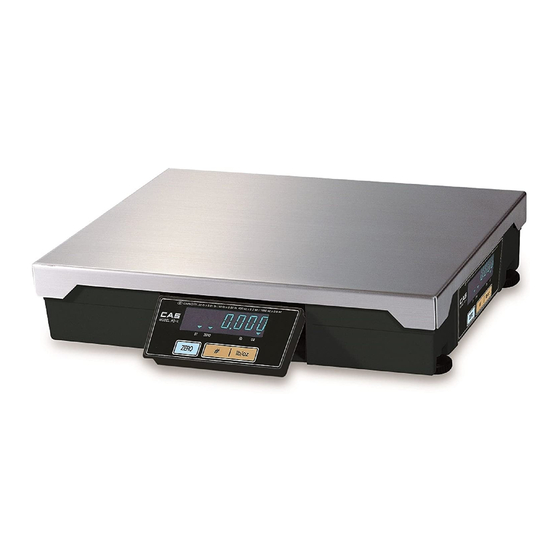
- Page 1 PD-II MANUAL...
-
Page 2: Table Of Contents
< Table of Contents > 1. Introductions ........................4 1.1. The Preface ..................... 4 1.2. Precautions ..................... 4 1.3. Specifications (CE) ..................5 1.4. Sealing Method....................8 2. Calibration Mode ......................9 2.1. How to Go to Normal mode (C – 0) ............... 10 How to Confirm Span Calibrated A/D Value(C –... - Page 3 3.2.1. TYPE-0 and1 INTERFACE ............... 23 3.2.2. COMMUNICATIONS BY USING UNIVERSAL 4-BIT PARALLEL .... 26 4. The Schematics and Diagram ..................31 4.1. System Block Diagram .................. 31 4.2. Circuit Diagram ....................32 4.2.1. Main ......................32 4.2.2. Power ....................... 33 4.2.3.
-
Page 4: Introductions
We believe that your needs will be satisfied and you will have proper reliability with in variable weight. This manual will help you with proper operations and care of the PD-II series. Please keep it handy for the future references. -
Page 5: Specifications (Ce)
1.3. Specifications (CE) MODEL PDII – 6kg PDII – 15kg PDII – 30kg PDII-60kg Single Interval Single Interval Single Interval Single Interval CAPACITY 6 kg 15 kg 30 kg 60 kg INTERNAL 1 / 90,000 1 / 90,000 1 / 90,000 1 / 90,000 RESOLUTION EXTERNAL... - Page 6 Pound(lb) Version (UL) MODEL PD2 – 15LB PD2 – 30LB PD2 – 60LB PD2-150LB Single Interval Single Interval Single Interval Single Interval 15 lb / 0.005 lb 30 lb/ 0.01 lb 60 lb/ 0.02 lb 150 lb / 0.05 lb Capacity Dual Interval Dual Interval...
- Page 7 Ounce (oz) Version (UL) MODEL PD2 – 300oz PD2 – 600oz PD2 – 1000oz PD2-2000oz Single Interval Single Interval Single Interval Single Interval 300 oz / 0.1 oz 600 oz / 0.2 oz 1000 oz / 0.5 oz 2000 oz / 1 oz Capacity Dual Interval Dual Interval...
-
Page 8: Sealing Method
1.4. Sealing Method... -
Page 9: Calibration Mode
2. Calibration Mode To go to calibration mode, turn on the power while pressing the calibration switch. The display shows “CAL” three times, and then “C-0”. Mode Selection : [#]key or [*] key Enter : [ZERO] key MODE DESCRIPTION C – 0 Normal Mode C –... -
Page 10: How To Go To Normal Mode (C - 0)
2.1. How to Go to Normal Mode (C – 0) To go to calibration mode, turn on the power while pressing the calibration switch. The display shows “CAL” three times, and then “C-0”. To go to Normal mode, press the [ZERO] key. How to Confirm Span Calibrated A/D Value(C –... -
Page 11: Capacity Display And Option Setting(C - 4)
2.4 Capacity Display and Option Setting(C – 4) For pariculars please inquire at CAS . Key operation : ◆ Press the ZERO key to enter setting value. ◆ Press the [#] key to change digit position. ◆ Press the [* ] key to have number Up. 2.4.1 UNIT, TARE Setting(C–4–1) Calibration Initial... -
Page 12: Comma Setting (C-4-3)
2.4.3 Comma Setting (C–4–3) Comma Decimal point Dislplay Display 0 : Down to two decimal point 1: Possible 1 : Down to three 0: Impossible decimal point 2.4.4 Save Setting(C–4–4) UNIT CHANGE 1: Possible 0: Impossible If NTEP(C-4-1 3 bit) is set, please do not care of “C-4-4”... -
Page 13: Real A/D Value(C - 6)
Real A/D Value(C – 6) (1) To go to calibration mode, turn on the power while pressing the calibration switch. The display shows “CAL” three times, and then “C-0”. (2) Press the [#] key until the display shows “C – 6”. (3) Press the [ZERO] key, the display shows real A/D value. -
Page 14: Gravity Constant (C - 9)
Gravity Constant (C – 9) (1) To go to calibration mode, turn on the power while pressing the calibration switch. The display shows “CAL” three times, and then “C-0”. (2) Press the [#] key until the display shows “C – 9”. (3) Press the [ZERO] key the display shows ”C91 “... - Page 15 Table 1 Description MENU RS-232 Serial ECR-TYPE 0 Most P.O.S, ECRs and Some TEC P.O.S System ECR-TYPE 1 ECR-TYPE 2 SHARP ER-Axxx, ER-A450T, New SANYO ECRs using RS-232 and others ECR-TYPE 3 Most P.O.S System ECR-TYPE 4 CRS, NCR2170, SAMAUNG ER-5100, ER5115 and Many other ECRs NCI General.
-
Page 16: Interface With External Device
3 INTERFACE WITH EXTERNAL DEVICE INTERFACE with RS-232C ECR(삼성), PC PD-II D-SUB Connector (9-PIN SUB CONNECTOR) 7-BIT ASCII code Even parity 1 stop bit 9600 baud rate 3.1.1 TYPE-2 INTERFACE : Discontinual RS-232C Interface SHARP ER-AXXX, ER-A450T, New SANYO ECRs using RS-232,TOLEDO 3213 etc. 1) PROTOCOL SCALE(PD-II) Command ------------... -
Page 17: Type-3 Interface
W : 57H (ASCII code) STX : 02H (ASCII code) CR : ODH (ASCII code) Weight : 12.34 lb SCALE W<57H> ------ ------ <02H><30H><31H><32H><33H><34H><0DH> : ASCII code 3.1.2 TYPE-3 INTERFACE : Continual RS-232C Interface SHARP ER-AXXX, New SANYO ECRs using RS-232,TOLEDO 3213 etc 1) PROTOCOL SCALE(PD-II) Command ------------... -
Page 18: Type-0 And Type-1 Interface
TRANSMISSION PROCEDURE (1) PD-II sends data to External Device whenever weight is changed after receiving <W> signal from the External Device. (2) PD-II stops sending data when receives <CR> signal from the External Device. External Device <W> ------ ----- DATA (If weight is changed) ------ DATA (If weight is changed) <CR>... -
Page 19: Type-4 Interface
41H = 15 kg 44H = 30 lb 43H = 6 kg 46H = 15 lb NA = 3 kg NA = 6 lb 42H = 25 kg 45H = 50 lb ii> Block Check Character : <BCC> has all data bytes except <STX> and <ETX> through exclusive OR(XOR). * Parity Bit : Even - Data Byte : <STX><ID><W5><W4><W3><W2><W1><BCC><ETX>... -
Page 20: Type-5 Interface
Bit6 Bit5 1 (Always 1) 1 (Always 1) Bit4 1 (Always 1) 1 (Always 1) Bit3 Bit2 1 = Scale at Zero 1 = Over Capacity Bit1 0 = Not at Zero 0 = Not Over Capacity 1 = Scale in Motion 1 = Under Capacity Bit0 0 = Stable... - Page 21 XX.XXX = Weight value LB = The Characters L and B KG = The Characters K and G OZ = The Characters O and Z b1b2 = Two status Characters i> Status Bytes Bit7 Parity Bit Parity Bit Bit6 Bit5 1 (Always 1) 1 (Always 1) Bit4...
-
Page 22: Type-6 Interface
3.1.6 TYPE-6 INTERFACE 8 Data bit Noneparity 1 stop bit 9600 baud ate SAMSUNG ECR (ER-670) 1> PROTOCOl EXTERNAL DEVICE SCALE(PD-II) <ENQ> ------------ Initiate communication ------------ <ACK> : Acknowledge the request of weight data <DC1> or <DC2> ------------ DC1 : For Weight Data DC2 : For All Data ( PD-II NOT USE) ------------ Send Data Block... -
Page 23: Type-7 Interface
3.1.7 TYPE-7 INTERFACE : RS-232C Interface 8 Data bit None parity 1 stop bit 9600 baud rate SAMSUNG ECR (SPAIN) 1) PROTOCOL SCALE(PD-II) Command ------------ <$> ------------ Response XXX.XXX <CR> $ : 24H (ASCII code) “.”... -
Page 24: The Schematics And Diagram
The Schematics and Diagram System Block Diagram 6-Digit VFD Display 부는 본체 및 Post 에 사용자가 간편하게 설치 하여 사용. VFD Driver (PT6311) Wire 길이는 1.5 m 이내로 함 Load ADC Circuit Cell (Dual Sloop type) C P U AC 220V Transformer (Z ERO ,TARE,Kg /Lb , POW ER ON/O FF KEY) -
Page 25: Circuit Diagram
Circuit Diagram 4.2.1 Main R3~5,14~16 uPD789177 0.5% Vddo Vdd1 To U14 IC(74HC670) Pin#15 AVdd To U14 IC(74HC670) Pin#1 To U14 IC(74HC670) Pin#2 To U14 IC(74HC670) Pin#3 Display Con 2 100u To U15 IC(74HC670) Pin#15 0.1u To U15 IC(74HC670) Pin#1 Vsso To U15 IC(74HC670) Pin#2 CON 5 Vss1... -
Page 26: Power
4.2.2 Power SW50 TRANSFORMER50 FUSE 16.5V/100mA KA7912 -12v AC MALE(220V) RB153 470uF 100uF CON1 8.8V/100mA AC220V Noise Filter (CA5-V32) CON7 To Digital Power(5V) FERITE KA7805 VDD(+5v) 29V/50mA 100uF 3.3u(tantal) RB153 1000uF 0.01u 4.7uF 1.65V/700mA 1.65V/700mA VEE(-30V) 1N4004 To VFD Driver 1N4004 No artwork 330uF/50V... -
Page 27: Display
4.2.3 Display U100 Key4 Grid8 Key3 Grid7 Key2 Grid6 Key1 Grid5 Grid4 Grid3 Grid2 Grid1 VDD1 U102 PT6311 VDD2 0.1u DOUT VDD3 10 k R 3,4,5 L1,2,3 TDK221 X 3 VDD(+5V) VEE (-30V) VEE(-30V) 10 k R 6,7,8 6110-PPD-2000-A Title PD-II DISPLAY PART (MAIN) Size Document Number... -
Page 28: Communication (Serial And Parallel)
4.2.4 Communication (Serial and Parallel) data 1 data 2 data 3 (Pin #38) D0 data 4 D0~D7 : Data0~Data7 (Pin #37) D1 DATA1 (Pin#1) From CPU (Pin #36) D2 FROM MAX232 PIN#14 Port 4 (Pin #35) D3 TO MAX232 PIN#13 R32 3K CLK 10 DATA2 (Pin #2) -
Page 29: Wiring Diagram
Wiring Diagram (Serial and Parallel Interface) POWER TRANS Power Serial Interface Device Trans SERIAL COMMUNICATION PARALLEL COMUNICATION CON8 CON5 INTERFACE CABLE ANALOG M/D MAIN LoadCell FL-PR3 (Flash Rom Write) DISPLAY... -
Page 30: Parts Location
Parts Location 4.4.1 Main and Power Part 4.4.1.1 4.4.1.2 Bottom... -
Page 31: Display Part
4.4.2 Display Part 4.4.2.1 4.4.2.2 Bottom... -
Page 33: Exploded View
5 EXPLODED VIEW... -
Page 35: Parts List
6 PARTS LIST PD-II Parts List PARTS NAME : PD-II [PPP-PD0-153G-PPPP-P1] Parts Code Parts Name Size Unit Q'ty Remark 140-AD3-EAMP-PA01-02 ANALOG MODULE ASS'Y AD-20H 140-PD2-EDIP-UN01-02 DISPLAY PCB ASS'Y PD-II 140-PD2-EMAP-UN01-02 MAIN PCB ASS'Y PD-II 140-PD2-EPWP-UN01-02 POWER PCB ASS'Y PD-II 140-PD2-MBOD-UN01-02 BODY ASS'Y PD-II 140-PD2-MCTB-UN01-02... - Page 36 PARTS NAME : DISPLAY ASS'Y [PPP-PD0-EDIS-PPPP-P1] Parts Code Parts Name Size Unit Q'ty Remark 2631-A00-0008-0 VFD CUSHION 43*8*1T(DB-1S) 43*8*1T (DB-1S) 6110-PPD-2000-A PCB-DISPLAY 6110-PPD-2000-0 (PD-II) 6110-PPD-2000-0(PD-II) 6224-IS0-6311-0 IC(FIP-DRIVER) PT6311 QFP 6527-ID3-0100-0 RESISTOR-CHIP 1/10W RR1220P-103D(10K) R2,3,4,5,6,7,8 6527-ID3-0560-0 RESISTOR-CHIP 1/10W RR1220P-563D(56K) RR1220P-563D(56K) 6712-CHP-0104-0 CHIP CONDENSER CL21F 104 KBNC CL21F 104 KBNC...
- Page 37 6527-ID0-0510-0 CHIP RESISTOR 1/10W RR1220P-510D(51Ω) R8,12,L17,19 6527-ID3-0100-0 RESISTOR-CHIP 1/10W RR1220P-103D(10K) R13,14,15,16,3,4,5,9,10 6527-ID3-1000-0 RESISTOR-CHIP 1/10W RR1220P-104D(100K) R6,R11 6670-T00-0470-0 INDUCTANCE 470μH L7,8 6704-C25-0330-0 ELECTRIC-CONDENSER 330UF/25V EC6,7,8,9 6712-CAP-0180-0 CHIP CAPACITOR 18PF/50V(CL21C180J) C16,17 6712-CHP-0104-0 CHIP CONDENSER CL21F 104 KBNC C5,14,19,18,32,33,? 6712-CHP-0471-0 CHIP CONDENSER CL21F 471 KBNC C35,36,37,38,39,40 6712-CHP-0472-0 CHIP CONDENSER...
- Page 38 PARTS NAME : POWER PCB ASS'Y [PPP-PD0-EPOW-PPPP-P1] Parts Code Parts Name Size Unit Q'ty Remark 6140-PPD-2000-A PCB-POWER 6140-PPD-2000-0 (PD-II 6140-PPD-2000-0 (PD-II) 6220-I00-7805-0 IC(REGULATOR) TA7805S 6220-I00-7912-0 IC(REGULATOR) LM7912CT 6236-IS0-0014-0 IC(C-MOS) 74HC14 6236-IS0-0032-0 IC(C-MOS) 74HC32D 6236-IS0-0074-0 IC(CMOS) 74HC74 U10,12 6236-IS0-0670-0 IC(C-MOS) 74HC670 U14,15 6236-IS0-7403-0 IC(C-MOS)
- Page 39 6704-C25-1000-0 ELECTRIC-CONDENSER 1000UF/25V 6704-C50-0004-0 ELECTRIC-CONDENSER 4.7uF/50V 6704-C50-0330-0 ELECTRIC-CONDENSER 330UF/50V 6710-CAP-0104-0 CERAMIC-CONDENSER 0.1UF/25V(50V) C1,2,3,4 6712-CHP-0103-0 CHIP CONDENSER CL21F 103 KBNC C7,8,9,10,22,23,24,25,26, 6712-CHP-0104-0 CHIP CONDENSER CL21F 104 KBNC 27,28,42 6712-CHP-0222-0 CHIP CONDENSER CL21F 222KBNC C20,21 6800-F00-3565-A EMI BEAD FILTER BFD-3565 R2 L1,2 NFB-103S(삼일부품) NFB-103S(삼일) 6830-F00-0040-0...
- Page 40 PARTS NAME : BODY ASS'Y [PPP-PD0-MBOD-PPPP-P1] Parts Code Parts Name Size Unit Q'ty Remark 1000-A00-0134-0 TRAY PD-II 1030-A00-0208-0 BODY COVER PD-II 1030-A00-0210-0 SIDE BRACKET PD-II 1050-A00-0002-0 SELECT S/W COVER 30*13*0.5T(AL) 1100-A00-0056-0 BODY PD-II 1261-A00-0009-0 LIMIT BOLT M5*0.8*9.2(BSBM 6Kg) 1502-A00-0306-0 SCREW-MACHINE(PH) M3*6 SELECT SWITCH COVER BODY COVER ,...
- Page 41 PARTS NAME : C/T BOX ASS'Y [PPP-PD0-MCTB-PPPP-P1] Parts Code Parts Name Size Unit Q'ty Remark 1260-A00-0015-0 SEALING BOLT M3*9(CI-3000A,CASTON) 7560-PAC-0001-0 AC CORD(ND공용) (내수.폴란드.필리핀) 무지(PD-II) 9100-PD2-0130-0 C/T BOX 9102-PD2-4640-0 460*405 (PD-II) 9204-AS0-0013-0 STYROFOAM BOX PD-II(400*160*100) 9301-A00-0003-0 POLY BAG(MANUAL) 170*250*0.05T 9303-A00-0004-0 POLY BAG(HEAD) 350*450*0.05T TRAY 9304-A00-0005-A...
- Page 42 PARTS NAME : DISPLAY ASS'Y [PPP-PD0-MDIS-PPPP-P1] Parts Code Parts Name Size Unit Q'ty Remark 1512-A00-0306-0 SCREW-TAPPING(PH)-2 M3*6 DISPLAY PCB 1512-A00-0308-0 SCREW-TAPPING(PH)-2 M3*8 FRONT CASE φ3*φ6*0.5 1550-A00-0305-0 WASHER (FLAT) FRONT CASE 2004-A00-0043-0 FRONT CASE PD-II 2004-A00-0044-0 BOTTOM CASE PD-II 2010-A00-0024-0 DISPLAY FILTER 104.9*34.4*1t (SMOG) PD-II(15kg) 영공...
- Page 43 PARTS NAME : POWER ASS'Y [PPP-PD0-MPOW-PPPP-P1] Parts Code Parts Name Size Unit Q'ty Remark 1030-A00-0211-0 TRANS BRACKET PD-II 1502-A00-0305-0 SCREW-MACHINE(PH) M3*5 NOISE FILTER 1502-A00-0306-0 SCREW-MACHINE(PH) M3*6 POWER PCB 1503-A00-0406-0 MACHINE SCREW (WPH) M4*6 TRANS φ3*φ6*0.5 1550-A00-0305-0 WASHER (FLAT) NOISE FILTER φ3 1552-A00-0300-0 WASHER (OTO)
Need help?
Do you have a question about the PD-II Series and is the answer not in the manual?
Questions and answers