Table of Contents
Advertisement
Quick Links
Advertisement
Table of Contents

Subscribe to Our Youtube Channel
Related Manuals for WONDOM ICP1


Summary of Contents for WONDOM ICP1
- Page 1 How to Program APM2 with WONDOM In-Circuit Programmer? VIDEO TUTORIAL...
- Page 2 JAB3 - 250 PC UI Control ICP5 Miumax (PC UI) How to Realize PC UI Control with WONDOM ICP Video Note: The products and documentation in red are processing and will be released soon. Open Source Files for PROGRAMMING Products...
- Page 3 Note: In this document, we will use WONDOM ICP3 as the example to show you how to program JAB3. The operation of WONDOM ICP1 is the same.
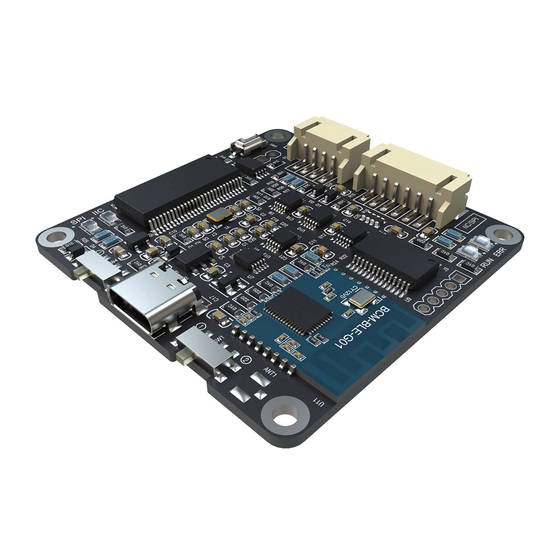
- Page 4 In-circuit Programmer For ADAU1701 Digital Signal - ICP1 WONDOM provides our own programming board named In-circuit Programmer For ADAU1701 Digital Signal - ICP1. It can be connected directly with JAB3 Board by a 6-pin cable without a pinboard to achieve programming the DSP integrated in JAB3.
- Page 5 Function: Programming + APP Control In-circuit Programmer with BLE Bluetooth for APP control - ICP3 WONDOM provides our own programming board named In-circuit Programmer with BLE Bluetooth for APP control - ICP3. It can be connected directly to JAB3 Board by a 6-pin cable without a pinboard to achieve programming the DSP integrated in JAB3.
-
Page 6: Quick Start
Quick Start To quickly get started with the Digital Signal Processor APM2, Extension Kit APM3 and In- Circuit Programmer, do the following steps: install the SigmaStuido software, plug in the ICP3, connect with APM2, power up the board, connect the audio cables, and program as follows: Click HERE to watch video. - Page 7 APM2 Interfaces POT4 POT2 POT1 POT3 Programming Reset Switch Port J11 6Pin Control Port Control Port J4 20Pin J3 20Pin Extension Port J1 10Pin Power Jack...
-
Page 8: Pin Definition
PIN Definition Description Description Analog Audio Input 0 Ground Pin Analog Audio Input 1 Ground Pin C Clock EEPROM Write Back Trigger C Data Self-Boot EEPROM Write Protect Active Low Reset Input DAC0 Digital to Analog Converter 0 Serial Input Port Data 2 DAC1 Digital to Analog Converter 1 Serial Input Port Data 3... - Page 9 PIN Definition 48 47 46 45 44 43 42 41 40 39 38 37 AGND AVDD PIN 1 ADC0 INDICATOR PLL_LF ADC_RES PVDD ADC1 PGND ADAU1701 RESET MCLKI TOP VIEW SELFBOOT he corresponence between four potentiometers and for POT4 OSCO (Not to Scale) ADDR0 RSVD...
-
Page 10: Frequency Range
Frequency Range he preset adjustable range of cut-off frequency of APM2 is as follows*. he adjustable range of the cut-off frequency of the he adjustable range of the upper frequency of the bass treble is 250Hz-2kHz. is 60Hz-120Hz; the adjustable range of the lower frequency of the bass is 200Hz-400Hz. - Page 11 Tips Input The interface extension kit (AP3) provides three sound channels of audio input but it could not be used at the same time. Potentiometer The cut-off frequency and gain could be modified through the potentiometer. POT1: Gain of bass POT2: Cut-off frequency of bass POT3: Cut-off frequency of treble POT4: Gain of treble...
-
Page 12: How To Programme
How to programme POWERING UP THE BOARD SETTING UP THE ICP3 CONNECTING ICP3 WITH APM2 INSTALLING SIGMASTUDIO SOFTWARE PROGRAMMING CONNECTING THE AUDIO CABLES... - Page 13 Installing Sigmastudio software 1.Open the provided zip file and extract the files to your computer. Alternately, insert the SigmaStudio CD into the PC optical drive and select the SigmaStudio folder. 2.Install Microsoft . NET Framework version 2.0, if it has not been previously installed. To do so, double-click “dotnetfx.exe”.
-
Page 14: Setting Up The Hardware
Setting up the hardware 1. Compile the needed program in advance. 2. Set the SW of ICP3 at (PROGRAM)* and connect the ICP3 to the computer with a USB cable. 3. Select “USBi” from the list on the left and drag it to the blank area on the right. -
Page 15: Connecting Audio Cables
Connecting Audio Cables This interface extension (APM3) provides three methods of audio input: ✓ RCA ✓ 3.5mm Aux 3.5mm PH-4PIN- ✓ PH-4PIN-2MM Headphone Output Connection This interface extension Use the 10 pin to 10 pin cornoid (APM3) provides three channels to connect APM2 with interface of audio output: extension kit (APM3) for playing... -
Page 16: Powering Up The Board
The Extension Kit (APM3) is powered by the Kernel Board (APM2) 3. Power of IC Programmer: WONDOM IC Programmer could be powered by: 1) 5V micro USB through micro USB charging port (J1) 2) External 5V DC Supply from DSP Kernel Board (APM2) - Page 17 Programming 1.Click the “Link Compile Connect” (see figure 2) 2.Click the “Link Compile Download” (see figure 3) and and you will find “Ready: Compiled” in the you will find “Active: Compiled” in the lower right lower right corner of your computer. corner of your computer.
-
Page 18: Power Up The System
SET SW ON ICP3 AT CONNECT APM2 WITH ICP3 CONTROL SYSTEM AFTER CONNECTED POWER UP THE SYSTEM DOWNLOAD APP “Miumax” AND PLAY MUSIC “Miumax” APP Note: Please take reference to <How to realize APP control with WONDOM ICP3.pdf> Android... -
Page 19: Troubleshooting
TROUBLE SHOOTING TROUBLE HOW TO SOLVE ➢ Make sure the ICP3 be recognized by PC Cannot writing the program into DSP successfully ➢ Make sure the SW of ICP3 is at (PROGRAM) and the SW1 on APM2 is set at (RUN) ➢... - Page 20 3F, Building F6, No. 9, Weidi Road, Xianlin, Qixia Dist., Nanjing, China Tel: +86-025-85260045 Web: store.sure-electronics.com Email: store@sure-electronics.com Skype: sureelectronics Online Shop YouTube...
Need help?
Do you have a question about the ICP1 and is the answer not in the manual?
Questions and answers