
Related Manuals for Leuze electronic MSI-S/R


Summary of Contents for Leuze electronic MSI-S/R
- Page 1 MSI-s/R Modular Safety Interface C O N N E C T I N G A N D O P E R A T I N G I N S T R U C T I O N S O r i g i n a l I n s t r u c t i o n s...
- Page 2 These connecting and operating instructions must be stored carefully. It must be available for the entire operating time of the MSI Safety Interfaces. The Leuze electronic GmbH + Co. KG is not liable for damages caused by improper use. Acquaintance with these instructions is an element of the knowledge required for proper use.
-
Page 3: Table Of Contents
Nomenclature MSI-s/R ........ -
Page 4: System Overview And Range Of Applications
System Overview and Range of Applications General Information The Modular Safety Interface (MSI) serves as a link Leuze electronic offers a range of additional MSI safety between one or more active optoelectronic protective interfaces with standard and special function, e.g. muting devices (AOPD), Type 2, Type 3 or Type 4, and the or cyclical operation (single break, double break). -
Page 5: Terms Used
Terms used AOPD Active Optoelectronic Protective Device RS 232 Interface RS 232 Diagn. Diagnosis Function S1, S2 Safety input 1, 2 External Device Monitoring S1 & S2 Indication Protected fields free/interrupted ESPE Electro-sensitive Protecting Equipment Select Selection of Cyclical Operation Fault Relay Fault Secondary Switching Device (switches to ON... -
Page 6: Nomenclature Msi-S/R
Nomenclature MSI-s/R MSI Modular Safety Interface standard: This version offers the following standard functions for eit- her 1 AOPD, Type 4, or up to 2 AOPDs, Type 2: – Start/restart interlock – External device monitoring – Diagnosis function Relay output: –... -
Page 7: Safety
• Use of Work Equipment Directive 89/655/EEC supple- (see table in chapter 2.1.1). For mounting, operating and mented by Directive 95/63 EC testing, document "MSI-s/R Modular Safety Interface Device" as well as all applicable national and internatio- • OSHA 1910 Subpart 0 nal standards, regulations, rules and directives must be observed. -
Page 8: Proper Use
The following table shows the safety-related characteri- person. stic parameters of the MSI-s/R modular Safety Interface Devices. Type in accordance with IEC/EN 61496 Type 4... - Page 9 • The Safety Interface Device is used in combination • In the event of changes to the MSI-s, all warranty with one or more Multiple Light Beam Safety Devices claims against the manufacturer of the Safety Interface or Safety Light Curtains to safeguard danger or hazard Device are rendered void.
-
Page 10: Foreseeable Misuse
2.1.2 Foreseeable misuse Any use other than that defined under the "intended use" Attention! or which goes beyond that use is considered improper Such instances can jeopardize the health and lives of the use! personnel operating the machinery and/or may cause damage to property. -
Page 11: Exemption Of Liability
(see • maintaining the safe operation of the machine chapter 2.2 and 2) Exemption of liability Leuze electronic GmbH + Co. KG is not liable in the • mounting and electrical connection are not properly following cases: performed • Safety Interface Device is not used as intended •... -
Page 12: System Configuration And Functions
System Configuration and Functions System Configuration Two microprocessors handle the redundant processing the OFF state until the reset button has been pressed of the signal sequences within the intelligent Modular and released (with start/restart interlock = standard ope- Safety Interface MSI. The results of the two processors rating mode). -
Page 13: Operating Modes And Functions
down Functions only in conjunction with external wiring, see Chapter 3.3: DIP Switch Function None Locking External Device Monitoring None restart interlock only static•- none•• – Down start/restart interlock* - none** dynamic – Factory setting: all switches down See Chapter 3.3.1.1 – 3.3.1.3 •... -
Page 14: Operating Mode: With Start/Restart Interlock - With Dynamic External Device Monitoring
The MSI safety interface is factory-set for the operating 3.3.1.1 Operating Mode: With Start/Restart Interlock – With Dynamic External Device Monitoring mode ”with start/restart interlock and dynamic external device monitoring”. If this setting is changed, these External wiring requirements: +24 V functions (i.e. -
Page 15: Operating Mode: With Start/Restart Interlock - With Static External Device Monitoring
3.3.1.2 Operating Mode: With Start/Restart Interlock 3.3.1.3 Operating Mode: With Start/Restart Interlock – With Static External Device Monitoring – Without External Device Monitoring External wiring requirements: External wiring requirements: +24 V +24 V Terminal 13 connected to Terminal 13 connected to ”Reset”... -
Page 16: Operating Mode: Without Start/Restart Interlock - Without External Device Monitoring
3.3.1.4 Operating Mode: Without Start/Restart Inter- 3.3.1.5 Operating Mode: With Start/Without Restart lock – Without External Device Monitoring Interlock – Without External Device Monito- ring External wiring requirements: +24 V External wiring requirements: +24 V Terminal 13 connected to 0 V Terminal 13 connected to 0 V ”Reset”... -
Page 17: Displays
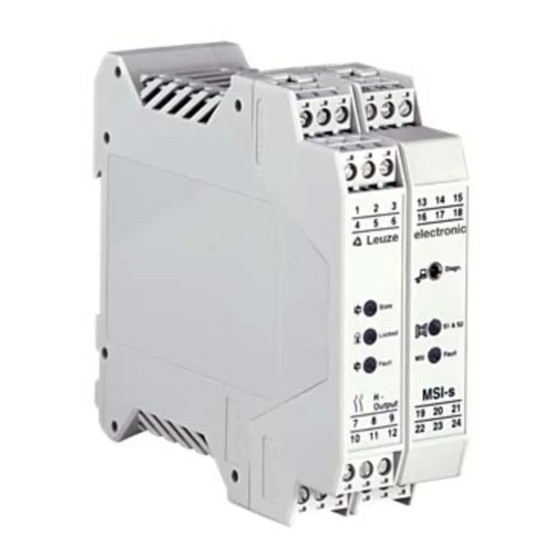
Displays A number of LEDs of various colors indicate the opera- using the integrated RS 232 interface and diagnosis ting status of the MSI modular safety interface. It is also connector. possible to show the LED displays on the PC monitor 13 14 15 16 17 18 Leuze... -
Page 18: Status Outputs
MSI Fault fault no fault Status Outputs Status outputs are not allowed to be used as safety- (see also Chapter Safety. Operating Conditions and related signals in release circuits Proper Use). AOPDs Test Leuze electronic R-Output MSI-s/R Diagn. State MSI-s... -
Page 19: Diagnosis System
Output /R Terminal Message Function Symbol Status Status Output Start/restart interlock lock locked active high not locked active low Safety-related switch status relay active high active low MSI-s Module Terminal Message Function Symbol Status Status Output Front Diagnosis, RS 232 –... - Page 20 Example: Leuze electronic Leuze electronic This enables the sequences at individual screw-type ped with on-line help and can be operated in either terminals to be tracked without the use of additional English or German. measuring instruments. The diagnosis function is equip-...
-
Page 21: Electrical Connection
Electrical Connection Installation Regulations The general safety precautions in Chapter 2 must be switched off and secured against being switched on observed. The electrical installation may be performed again. only if there is no voltage applied, and it must be performed by trained specialists. - Page 22 and vice versa (T2=>S1). The AOPD response time to a If type 2 AOPDs are connected: test request must be in a range of 2 to 18 ms. See Example 3. • when cables are laid with protection according to EN ISO 13849-1, a Performance Level up to d and All available safety inputs must be occupied! In case category 2 can be achieved...
- Page 23 Example 1 Example 2 Example 3 Example 4 1 AOPD Typ 4 with 2 safety- 1 AOPD Typ 4 with 2 nor- 2 AOPD Typ 2 with one 1 AOPD Typ 2 with one related transistor outputs mally open relay contacts. safety-related transistor out- safety-related transistor out- and internal cross connec-...
-
Page 24: Connecting Machine Controls
The safety-related parts of the controls comprise more quickly as possible. These factors, as well as the re- than the MSI-s/R described above. They also include sponse times of AOPDs and the MSI, must be taken into successive control elements and even power transmis- consideration when calculating the safety distance. -
Page 25: Connection Circuit Diagram, Examples
Connection Circuit Diagram, Examples The connection examples below show a wiring sugge- an EMERGENCY STOP button. stion for the MSI-s/R as well as a connection example for +24 V +24 V EMERGENCY STOP button 24 22 23 T1 T2 S1 S2... - Page 26 AOPD Type 4 Command device for releasing the start/restart interlock Feedback loop for external device monitoring Pin 7 Indicating output ”status safety outputs” Pin 6 Indicating output ”status start/restart interlock” Output Signal Switching Devices (OSSDs) Switching off path with two-channel control Switching off path with one-channel control Suitable spark suppression required In general, both of the contacts must be used in the subsequent...
-
Page 27: Technical Data And Ordering Information
Technical Data and Ordering Information MSI-s/R Version, Type MSI-s Modular Safety Interface Type in accordance with IEC/EN 61496 Type 4 SIL in accordance with IEC 61508 SIL 3 Performance Level (PL) in accordance PL e with ISO 13849-1: 2008 Category in accordance with ISO 13849-1 Cat. - Page 28 Control input Feedback of positive-guided contacts from downstream relays (see connection External device monitoring (EDM) diagram in Chapter 5) Safety outputs Relay outputs via /R-Output (Technical Data, see below) Supply voltage 24 V DC, ± 20%, external power supply (PELV, EN 60204-1) with safe mains separation and equalization for 20 ms voltage interruption required Current consumption approx.
-
Page 29: R-Output
/R-Output OSSD safety outputs 2 safety-related normal open contacts, switching voltage/switching current 60 V DC, 250 V AC, 5 A max. Minimum switching current 20 mA OSSD external fusing (EN 60269-1) 4A gG D-fuse Contact currents (IEC EN 60947-5-1) AC15, 3A DC13, 2A OSSD response time MSI for AOPD Type 4, transistor outputs... -
Page 30: Dimensional Drawing
10 11 12 22 23 35 * *) Stringing together without distance possible 113.6 Ordering Information Type Part No. MSI-s/R 549900 MSI diagnosis software 549930 PC cable 3 m 549953 PC cable 5 m 549955 /R output subassembly (replacement part) -
Page 31: Ec Declaration Of Conformity
EC Declaration of Conformity You can download this EC Declaration of Conformity from the Internet under: http://www.leuze.com/interfaces MSI-s...