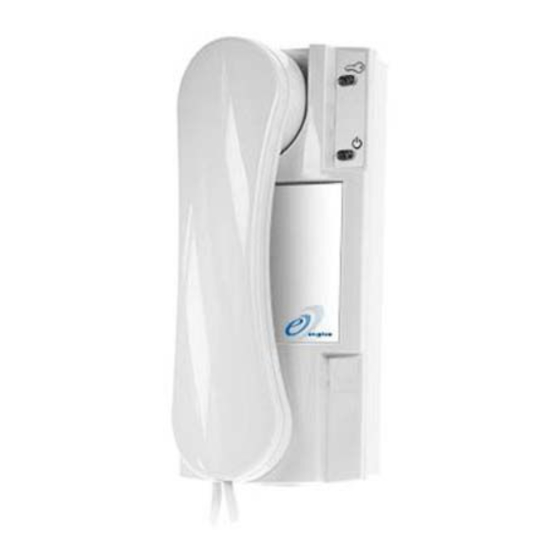
Entryphone 500 Series Schematics, Connection Diagrams And Installer's Notes
Hide thumbs
Also See for 500 Series:
Summary of Contents for Entryphone 500 Series
- Page 1 Entryphone ® DOOR ENTRY SYSTEMS 500 Series Video Schematics, connection diagrams and installer's notes For the system installed at:...
- Page 2 4 Way Splitter Power Supply Telephones Multi-button Entrance Single button Relay Unit Unit. Entrance Unit Door Release. Timeswitch Remote Camera see pages 6/7 see pages 4/5 and 12/13 DIP Switch Extension Jumper Setting Setting Sounder see pages 4/5 Entryphone ® page 2...
- Page 3 There are no individual call lines for the 500 series systems, instead each phone has a switch setting that should be set when the telephone is installed.
-
Page 4: System Description
The camera button on the phone will switch between cameras or lock view to one camera. Single button panel's call address is set to 01. J2V Link (see notes) Entryphone ® page 4... - Page 5 12vDC Max 300mA 12 0 V Key: line function 1 Video - 2 Video + 3 Data 4 24V- 5 24V+ 6 Lock Data + 7 Lock Data - GRN/ WHT/ BLU/ WHT/ ORG/ BRN/ WHT/ Entryphone ® page 5...
- Page 6 Trades time-switch allows access at preselected times via a button on the entrance panel. Note: In this example the link in the power supply is removed as the input terminals are mid-line. Entryphone ® page 6...
- Page 7 1D 2D 3D 4D 5D 6D 7D Lock Release Key: line function 1 Video - 2 Video + 3 Data 4 24V- 5 24V+ 6 Lock Data + 7 Lock Data - GRN/ WHT/ BLU/ WHT/ ORG/ BRN/ WHT/ Entryphone ® page 7...
- Page 8 Jumpers are removed in mid-line apparatus. Note: In this example the power supply is in a different location to the splitter. If they were in the same place no splitter would be required. Entryphone ® page 8...
- Page 9 OUT 2 DOOR UNIT AUX PSU Key: line function 1 Video - 2 Video + 3 Data 4 24V- 5 24V+ 6 Lock Data + 7 Lock Data - GRN/ WHT/ BLU/ WHT/ ORG/ BRN/ WHT/ Entryphone ® page 9...
- Page 10 The diagrams here show just two doors served but the DCU can be daisy-chained for additional panels. Termination links (jumpers) must be removed in mid-line apparatus. Entryphone ® page 10...
- Page 11 Lock Release ENTRANCE PANEL ENTRANCE PANEL Key: line function 1 Video - 2 Video + 3 Data 4 24V- 5 24V+ 6 Lock Data + 7 Lock Data - GRN/ WHT/ BLU/ WHT/ ORG/ BRN/ WHT/ Entryphone ® page 11...
-
Page 12: Panel Connections
Speaker (see fig.3) connector *Intercom mode (see fig.4) (Plan2) connector 2nd Camera 500 series entrance panels are inter-equipment input supplied with the 500LSV loud- connector (see fig.7) speaking amplifier assembly fitted and the call buttons are pre-wired. It is not necessary for the installer to change the button wiring. - Page 13 Panel connections Fig.2 Matrix connection numbers 1-49 Fig.4 Fig.5 Speaker Microphone Fig.1 Matrix connection to buttons 1- 11 shown Fig.6 Fig.7 Panel camera 2nd Camera Fig.3 Back-lighting Entryphone ® page 13 (note wired in series)
- Page 14 To work out the decimal value of the binary code add the decimal values of each switch together. This example shows switches 2 (binary value 2), 4 (binary value 8) & 5 (binary value 16) down. 8 4 2 1 Therefore 2+8+16 = 26. Binary Value Entryphone ® page 14...
- Page 15 Installer's notes Entryphone ® page 15...
- Page 16 The Entryphone Company Limited, 23 Granville Road, London, SW18 5SD 020 8870 8635 020 8874 0066 enquiries@entryphone.co.uk www.entryphone.co.uk ®ENTRYPHONE is a trade mark registered in Britain No. B1037141.


Need help?
Do you have a question about the 500 Series and is the answer not in the manual?
Questions and answers