
Related Manuals for miniDSP MINISHARC


Summary of Contents for miniDSP MINISHARC
- Page 1 SHARC MINI OMPACT UDIO ROCESSOR OARD WITH FIR C APABILITY User Manual miniDSP Ltd, Hong Kong / www.minidsp.com / Features and specifications subject to change without prior notice...
- Page 2 I2S master/slave clarifications added 17-03-2014 V1.5 Clarifications for SPDIF/I2S channel assignments 29-12-2014 V2.0 Revised full manual 31 July 2016 V2.1 Corrected miniDAC8 information 24 October 2016 miniDSP Ltd, Hong Kong / www.minidsp.com / Features and specifications subject to change without prior notice...
-
Page 3: Table Of Contents
I2S usage notes ............................22 S/PDIF connectivity ..........................22 Plugin installation.............................. 23 Windows ..............................23 Mac OS X ..............................24 Plugin Architecture ............................25 miniSHARC 4x8 plugins ..........................25 6.1.1 Input tab ............................25 6.1.2 Routing tab ............................26 6.1.3 Output tab ............................ - Page 4 Biquad design software ........................44 Additional information ............................45 Specifications ............................45 MCU firmware update ..........................46 Troubleshooting ............................47 Obtaining support ............................ 47 miniDSP Ltd, Hong Kong / www.minidsp.com / Features and specifications subject to change without prior notice...
-
Page 5: Important Information
YSTEM EQUIREMENTS To configure the miniDSP audio processor, you will require a Windows PC or Apple Mac OS X computer with the following minimum specification: Windows • PC with 1GHz or higher processor clock speed. Intel® Pentium®/Celeron® family, or AMD K6®/AMD Athlon®/AMD Duron®... -
Page 6: Warranty Terms
Finally, note that the miniDSP audio processor is a very flexible device, and many of the questions we receive at the tech support department are already answered in this user manual and in the online application notes the miniDSP.com website. So please take the time to carefully read this user manual and the online technical support. -
Page 7: Product Overview
The audio processing functionality of the board is implemented via the use of a software plugin. Depending on the plugin and accessory boards used, the miniSHARC currently supports up to 4 input channels and 8 output channels. For more information on the available plugins, see Choosing a plugin on page 8. -
Page 8: Choosing A Plugin
1.2 C HOOSING A PLUGIN There are three plugins that operate with the miniSHARC board. These are summarized below. Table 1. miniSHARC plugins miniSHARC 4x8 miniSHARC 4x8 OpenDRC 2x2 Internal sample rate 48 kHz 96 kHz 48 kHz Number of input channels... -
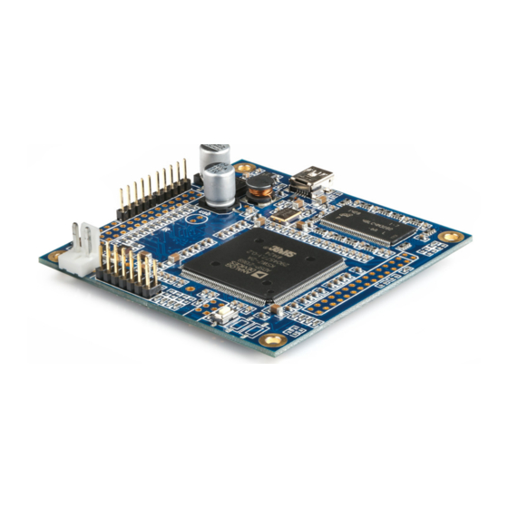
Page 9: Board Overview And Connectivity
This diagram shows the layout of the miniSHARC board. Note: the miniSHARC is delivered with two different header configurations. By default: If the miniSHARC is ordered alone, it will be delivered without the 30-pin headers for J1 and J2 soldered. •... -
Page 10: Dc Power
2.2 DC P OWER The miniSHARC accepts a regulated DC power supply on the 2-pin connector. A short cable from a 2.1 mm panel mount DC power socket is included with the kit purchase. Standalone use When the miniSHARC is not used with any of the miniDSP accessories that take power from the miniSHARC board, the miniSHARC can be powered with a DC supply in the range of 5 to 24 V. -
Page 11: Usb
2.3 USB The miniSHARC board has an onboard USB Mini-B socket. This can be connected directly to a computer with a standard Type A to Mini-B cable. For installation into a chassis, the miniSHARC kit has a 5-pin header (standard 0.1”/2.54mm pitch). This can be connected to a panel-mount USB connector via a commonly available cable assembly. -
Page 12: J1 Expansion Header
LRCLK_SPDIF (Not used in current firmware) BCLK_SPDIF (Not used in current firmware) MCLK I2S_DATA_IN1&2 I2S_DATA_IN3&4 I2S_DATA_IN5&6 I2S_DATA_IN7&8 I2S_IN_LRCLK I2S_IN_BCLK I2S_DATA_OUT1&2 I2S_DATA_OUT3&4 I2S_DATA_OUT5&6 I2S_DATA_OUT7&8 I2S_OUT_LRCLK I2S_OUT_BCLK 3.3V 3.3V miniDSP Ltd, Hong Kong / www.minidsp.com / Features and specifications subject to change without prior notice... -
Page 13: Off-The-Shelf Accessories And Connection
(applies when used together with DIGI-FP or DA-FP). After mounting in the enclosure, connect the supplied 5-pin cable between the VOL-FP board and the miniSHARC board as shown in the photograph below. Note carefully the orientation of the connectors as shown in the photograph. -
Page 14: Infrared Remote Control
3.1.2 Infrared remote control The miniSHARC plugins can “learn” the control codes of your current remote if it supports one of the following remote control codes: • Sony • • Philips RC6 To initiate the learning process, drop down the IR Remote menu and select IR learning. Click on the Learn button for an operation, and then press the desired button on the remote control. -
Page 15: Digi-Fp
The DIGI-FP contains an on-board asynchronous sample rate convertor (ASRC) that converts the input signal to the sample rate set by the miniSHARC plugin (48 or 96 kHz). In addition, it provides a USB Type B socket. The DIGI-FP requires that two cables (supplied with the DIGI- FP) be connected to the miniSHARC. -
Page 16: An-Fp And Da-Fp
Neutrik panel-mount connectors. Both boards also provide a USB Type B socket. The AN-FP and DA-FP require that three cables (supplied with the board) be connected to the miniSHARC. A 14- pin flat ribbon cable carries I2S and control signals. The AN-FP and DA-FP also require separate 5V power. To facilitate a simple wiring scheme, the AN-FP and DA-FP provide two power connectors, which can be used as shown in the photograph below. -
Page 17: Minidac8
30-pin headers installed for both J1 and J2. The USB and VOL-FP headers must be right-angle types to ensure adequate clearance between the boards. This photograph shows the key connectivity points: Note that to use the miniDAC8, the miniSHARC must be in I2S master mode (page 19). miniDSP Ltd, Hong Kong / www.minidsp.com... -
Page 18: O Interfaces
5 though 8 are not accessible in the current firmware and plugins. The I2S data line for channels 3 and 4 is used by the SPDIF input, and is accessible by the miniSHARC 4x8 plugins (both 48 kHz and 96 kHz versions). -
Page 19: I2S Clock Modes
Together, the word clock and bit clock are referred as a clock domain. The miniSHARC board has three clock domains: I2S input • • I2S output SPDIF input • Depending on the I2S clock mode, the clocks may be provided by the miniSHARC or external circuitry, and the data line may or may not be subject to sample rate conversion. -
Page 20: Input Slave Mode
(48 or 96 kHz). The connections are shown in Figure 2 below. To put the miniSHARC into input slave mode, pull pin 8 of the J1 expansion header low. This is easily accomplished by connecting pin 8 to pin 6 (GND). -
Page 21: Output Slave Mode
Figure 3. Output slave mode To put the miniSHARC into output slave mode, pull both pin 8 and pin 9 of the J1 expansion header low. This is easily accomplished by connecting them to pin 6 and/or pin 5 (GND). -
Page 22: I2S Usage Notes
I2S_DATA_IN3&4 always has asynchronous sample rate conversion applied, from the SPDIF clock domain to the miniSHARC’s clock domain, regardless of the I2S clock mode. The SPDIF input can therefore be driven at any sample rate from 32 to 192 kHz. -
Page 23: Plugin Installation
Navigate to the OpenDRC Plug-ins section of User Downloads, then download the zip file (or files) under the heading miniSHARC 4x8 48kHz, miniSHARC 4x8 96k, or OpenDRC 2x2 Double-click on it to unzip it. Then follow the installation procedure below according to your computer type. -
Page 24: Mac Os X
To install the miniDSP software, open the Mac folder of the download, and double-click on the disk image (“.dmg”) file to open it in a new window. Then double-click on the installer program, Install miniSHARC 4x8.app, Install miniSHARC 4x8 96k.app, or Install OpenDRC-2x2.app. Once installation is complete, the plugin will automatically start. -
Page 25: Plugin Architecture
MINI PLUGINS This screenshot shows the miniSHARC 4x8 plugin with the key areas highlighted: 6.1.1 Input tab The Input tab displays a row of input channel control strips: two for I2S input channels 1 and 2, and two for the SPDIF inputs (I2S channels 3 and 4). -
Page 26: Routing Tab
The Output tab displays a row of output channel control strips. All channels are identical. The output controls are described on page 29 and in Section 7. miniDSP Ltd, Hong Kong / www.minidsp.com / Features and specifications subject to change without prior notice... -
Page 27: Opendrc-2X2 Plugin
28 and 29. The FIR filter blocks are described on page 38. 6.3 C OMMON FEATURES The Mute button disables all audio output: The Master volume display shows the current volume setting: miniDSP Ltd, Hong Kong / www.minidsp.com / Features and specifications subject to change without prior notice... -
Page 28: Input Channel Strips
Each input channel has a customizable label, which is shown at the top of the channel strip. This label also appears on the Routing tab (in the miniSHARC plugins). To change the label, click on it, type a new label (up to eight characters), and press the Return key. -
Page 29: Output Channel Strips
Each output channel has a customizable label, which is shown at the top of the channel strip. This label also appears on the Routing tab (in the miniSHARC 48 plugins). To change the label, click on it, type a new label (up to eight characters), and press the Return key. -
Page 30: Synchronizing With The Processor
Communication with the processor takes place over a USB connection. Note that USB connection or to on the miniSHARC board is used for control purposes only. Audio data cannot be streamed to the processor over USB, except by using an external USB-to-I2S interface such as the miniStreamer or USBStreamer. -
Page 31: Working With Configurations
(as long as the Synchronize Config button is selected). The configuration contained in the miniDSP hardware unit cannot be uploaded back to the computer. Therefore, you must save your configuration to a file if you wish to recover from any changes you make while in offline mode. -
Page 32: Saving And Loading Configurations
Otherwise, the reset will take place in the user interface only, and the new configuration data will be downloaded to the processor next time it is synchronized. miniDSP Ltd, Hong Kong / www.minidsp.com... -
Page 33: Keyboard Shortcuts
6.8 K EYBOARD SHORTCUTS The miniSHARC 4x8 plugin supports the use of the keyboard for many operations. The Tab key moves the focus from the current user interface element to the next. A blue-grey surrounding box usually indicates the user interface element with the focus. Shift-Tab moves the focus in the opposite direction. -
Page 34: Signal Processing Blocks
Hovering the mouse over the curve brings up an overlay showing the frequency and the attenuation at that frequency. miniDSP Ltd, Hong Kong / www.minidsp.com / Features and specifications subject to change without prior notice... - Page 35 To link a channel, select the other channel from the drop-down menu at the top left of the Xover screen, and click the Link checkbox. miniDSP Ltd, Hong Kong / www.minidsp.com...
-
Page 36: Parametric Eq
To link a channel, select the other channel from the drop-down menu at the top left of the PEQ screen, and click the Link checkbox. miniDSP Ltd, Hong Kong / www.minidsp.com... - Page 37 Hz). This filter type is similar to PEAK but gives more accurate results for low frequencies. Note that activating any SUB_EQ filter reduces the number of available filters on that channel by one (from 10 to 9 for miniSHARC plugins, or from 6 to 5 for the OpenDRC plugin.) Frequency For the PEAK and SUB_EQ filter types, this is the center frequency of the peak or dip.
-
Page 38: Fir Filtering And Design
7.3 FIR FILTERING AND DESIGN FIR filtering is a powerful and advanced feature of the miniSHARC and associated plugins. It allows construction of complex arbitrary equalization and crossover filters with independent control of amplitude and phase. The parameters of each FIR filter are set in the FIR settings window: Browse Opens a filter browser to select a file containing FIR filter coefficients. -
Page 39: Fir Filtering Overview
• In the OpenDRC 2x2 plugin, each channel has a fixed number of taps (6144). • In the case of the miniSHARC 4x8 plugins, taps can be distributed across the eight output channels, with the limitation that each output channel must have 6 or more taps and can have no more than 2048 taps. The decision on how many taps to allocate to each channel up to you, and should be determined after working with an FIR filter design program (see below). -
Page 40: Invert And Mute
(0.02 ms) increments. The time delay corresponds to a distance. This distance is shown in centimeters below the entry box. miniDSP Ltd, Hong Kong / www.minidsp.com / Features and specifications subject to change without prior notice... -
Page 41: Compressor
The optimum settings may need to be tuned by ear. For more information, see the Wikipedia article Dynamic range compression. miniDSP Ltd, Hong Kong / www.minidsp.com / Features and specifications subject to change without prior notice... -
Page 42: Custom Biquad Programming
In advanced mode, the biquad coefficients can be pasted directly into the user interface. These coefficients must be calculated using a design program – see Biquad design software below for suggestions. miniDSP Ltd, Hong Kong / www.minidsp.com / Features and specifications subject to change without prior notice... - Page 43 This file can be generated by Room EQ Wizard (REW) or by other programs. The design program must be set for a 48 kHz sample rate if using the miniSHARC 4x8 plugin, and a 96 kHz sample rate if using the miniSHARC 4x8 96k plugin. The number of filters is limited to a maximum of ten.
-
Page 44: Biquad Design Software
It includes the ability to automatically generate a bank of parametric EQ biquads based on a measurement. These coefficients can be saved to a file from REW and loaded directly into a PEQ bank in a miniDSP plugin. Room EQ Wizard can be downloaded here: http://www.roomeqwizard.com/#downloads •... -
Page 45: Additional Information
Driverless USB 2.0 control interface for Windows and Mac OS X Audio resolution 24-bit input and output miniSHARC 4x8 and OpenDRC 2x2 plugins: 48 kHz internal sample rate miniSHARC 4x8 96k plugin: 48 kHz internal sample rate Audio processing Analog Devices SHARC 32-bit floating-point processor Specific processing functionality depends on loaded plugin. -
Page 46: Mcu Firmware Update
IS IN PROGRESS. DOING SO MAY “BRICK” YOUR PROCESSOR. To update the MCU firmware: Download and install the latest version of either the miniSHARC 4x8 or OpenDRC 2x2 plugin from the User Downloads section of the miniDSP website. Connect the processor to your computer via USB. -
Page 47: Troubleshooting
If you are not confident in your ability to design, debug and interface external circuitry to the miniSHARC, please consider using our of-the-shelf interface accessories (section 3) or our pre-assembled “box” units in the OpenDRC and Dirac Series.
Need help?
Do you have a question about the MINISHARC and is the answer not in the manual?
Questions and answers