Advertisement
Quick Links
Advertisement

Related Manuals for Gree Bright Series


Summary of Contents for Gree Bright Series
- Page 1 Bright Series Introduction and Features Remarks Model...
- Page 2 Remarks Model...
- Page 3 Bright Series Remarks Model...
- Page 4 Model Remarks...
-
Page 5: Specifications And Technical Parameters
Bright Series Specifications and Technical Parameters Model GWCN18B5TD1CA GWHN18B5TD1CA Function COOLING COOLING HEATING Rated Voltage 220V~ 220V~ Rated Frequency 60HZ 60HZ Total Capacity (W/Btu/h) 18000Btu/h 18000Btu/h 20000Btu/h Power Input (W) 2200 2200 2250 Rated Input (W) 3300 3375 3375 Rated Current (A) 15.34... - Page 6 Model of Outdoor Unit GWCN18B5TD1CA/O GWHN18B5TD1CA/O Compressor Model AWZ5517EXN Compressor Type rotary compressor L.R.A. (A) Compressor RLA(A) Compressor Power Input(W) 1580 Overload Protector Throttling Method Capillary Starting Method Capacitor Working Temp Range ( ℃ ) -7 ℃≤ T ≤ 43 ℃ Condenser Aluminum fin-copper tube ¢...
- Page 7 Bright Series Model GWCN24B5TD1CA GWHN24B5TD1CA Function COOLING COOLING HEATING Rated Voltage 220V~ 220V~ Rated Frequency 60HZ 60HZ Total Capacity (W/Btu/h) 24000Btu/h 24000Btu/h 26400Btu/h Power Input (W) 3050 3050 3100 Rated Input (W) 4575 4650 4650 Rated Current (A) 20.8 Air Flow Volume (m...
- Page 8 Model of Outdoor Unit GWCN24B5TD1CA/O GWHN24B5TD1CA/O Compressor Model AWZ5517EXN Compressor Type rotary compressor L.R.A. (A) Compressor RLA(A) Compressor Power Input(W) 2160 Overload Protector Throttling Method Capillary Starting Method Capacitor Working Temp Range ( ℃ ) -7 ℃≤ T ≤ 43 ℃ Condenser Aluminum fin-copper tube ¢...
- Page 9 Bright Series Model GWCN18B5TD1LA GWHN18B5TD1LA Function COOLING COOLING HEATING Rated Voltage 220V~ 220V~ Rated Frequency 60HZ 60HZ Total Capacity (W/Btu/h) 18000Btu/h 18000Btu/h 20000Btu/h Power Input (W) 2200 2200 2250 Rated Input (W) 3300 3375 3375 Rated Current (A) 15.34 15.34...
- Page 10 Model of Outdoor Unit GWCN18B5TD1LA/O GWHN18B5TD1LA/O Compressor Model AWZ5517EXN Compressor Type rotary compressor L.R.A. (A) Compressor RLA(A) Compressor Power Input(W) 1580 Overload Protector Throttling Method Capillary Starting Method Capacitor Working Temp Range ( ℃ ) -7 ℃≤ T ≤ 43 ℃ Condenser Aluminum fin-copper tube ¢...
- Page 11 Bright Series Model GWCN24B5TD1LA GWHN24B5TD1LA Function COOLING COOLING HEATING Rated Voltage 220V~ 220V~ Rated Frequency 60HZ 60HZ Total Capacity (W/Btu/h) 24000Btu/h 24000Btu/h 26400Btu/h Power Input (W) 3050 3050 3100 Rated Input (W) 4575 4650 4650 Rated Current (A) 20.8 Air Flow Volume (m...
- Page 12 Model of Outdoor Unit GWCN24B5TD1LA/O GWHN24B5TD1LA/O Compressor Model AWZ5517EXN Compressor Type rotary compressor L.R.A. (A) Compressor RLA(A) Compressor Power Input(W) 2160 Overload Protector Throttling Method Capillary Starting Method Capacitor Working Temp Range ( ℃ ) -7 ℃≤ T ≤ 43 ℃ Condenser Aluminum fin-copper tube ¢...
- Page 13 Bright Series Model GWCN24B5NE1IB GWCN24B5NE1NB Function COOLING COOLING Rated Voltage 230V~ 230V~ Rated Frequency 50HZ 50HZ Total Capacity (W/Btu/h) 24000Btu/h 24000Btu/h Power Input (W) 2450 2450 Rated Input (W) 3430 3430 Rated Current (A) 14.9 14.9 Air Flow Volume (m...
- Page 14 Model of Outdoor Unit GWCN24B5NE1IB/O GWCN24B5NE1IB/O Compressor Model Xian Qingan Xian Qingan Compressor Type Rotary Rotary L.R.A. (A) Compressor RLA(A) Compressor Power Input(W) 2130 2130 Overload Protector Throttling Method Capillary Capillary Starting Method Capacitor Capacitor Working Temp Range ( ℃ ) -5 ℃≤...
- Page 15 Bright Series Model GWHN24B5NK3FA GWHN24B5NK1NA Function COOLING HEATING COOLING HEATING Rated Voltage 220-240V~ 220-240V~ Rated Frequency 50HZ 50HZ Total Capacity (W/Btu/h) 6000W 6600W 24000Btu 26400Btu Power Input (W) 2180 2200 2500 2600 Rated Input (W) 3050 3080 3750 3900 Rated Current (A) 13.3...
- Page 16 Model of Outdoor Unit GWHN24B5NK3FA/O GWHN24B5NK1NA /O C-R191H5C Compressor Model 5VS245EAA21 Compressor Type rotary compressor rotary compressor L.R.A. (A) 45.5 Compressor RLA(A) 10.4 Compressor Power Input(W) 2125 2285 Overload Protector Throttling Method Capillary Capillary Starting Method Capacitor Capacitor Working Temp Range ( ℃ ) -7 ℃≤...
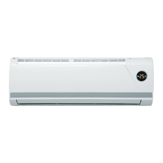
- Page 17 Bright Series C omponent Name Indoor Unit Air inlet Display Auto key Power plug panel Wrapping Tape filter Guide Louver Wall Pipe Air outlet Display window receiving Cooling Power/Run Heating Preset window temp. Outdoor Unit Air inlet Connecting pipe Drainage Pipe...
- Page 19 Bright Series Overall and Installing Dimension Overall and Installing Dimension of Indoor Unit Air inlet grill Left Tube-exit Sign Top View Right Tube-exit Sign Rear View Ceiling...
- Page 20 Air inlet grill Left Tube-exit hole Top View Right Tube-exit hole Unit: mm Rear View wall plate...
- Page 21 Bright Series Air inlet grill Left Tube-exit hole Top View Right Tube-exit hole Rear View Unit: mm Ceiling...
- Page 22 Air inlet grill Top View Left Tube-exit Sign Right Tube-exit Sign Rear View Ceiling...
- Page 23 Bright Series O verall and Installing Dimension of Outdoor Unit Unit: mm Over 600 Over 600 Over 600 Over 600 Bolt Wrench...
- Page 25 Bright Series Unit: mm Over 600 Over300 Over 600 Over 600 Bolt Wrench...
-
Page 26: Electrical Diagram
5 5 5 5 5 Electrical Diagram In case of any change in the Electrical Diagram shown above, please follow the drawing on cabinet. - Page 27 Bright Series In case of any change in the Electrical Diagram shown above, please follow the drawing on cabinet.
- Page 29 Bright Series...
- Page 30 6 6 6 6 6 Remote Controller Function Manual and Operating Instructions 6 6 6 6 Remote Controller Function Manual This function manual is for: 6.1.1 Temperature Parameters Indoor preset temperature (T preset Indoor ambient temperature (T amb. 6.1.2 Basic Functions Once energized, the compressor should in no way be restarted unless after 3-minute time interval at least.
- Page 31 Bright Series When T -2 ≤T ≤T + 2 , the unit will run under dehumidifying mode, in which case the indoor fan will keep ℃ ℃ preset amb. preset run at low speed, while the compressor and outdoor fan will run 6 minutes and stop 4 minutes so repeated in cycle.
- Page 32 Noise Silencing Protection If the unit is stopped by pressing ON/OFF,or mode switching, the reversal valve will be stopped after 2-minute lag. Overcurrent Protection the same as that under cooling mode( only indoor fan will run at low speed for 60 seconds before it is stopped).
- Page 33 Bright Series 6.1.3.4.2 Malfunction Display When the PG motor is locked, the nixie tube will display "H6 " and the Run indicator will blink at the same time.When the room temp. sensor is short/ open circuit, the nixie tube will display "F1" and the cooling indicator will blink at the same time.
- Page 34 6 6 6 6 Remote Controller Function Manual This function manual is for: 6.2.1 Temperature Parameters Indoor preset temperature (T preset Indoor ambient temperature (T amb. 6.2.2 Basic Functions Once energized, the compressor should in no way be restarted unless after 3-minute time interval at least. For the first energization, the compressor will be started without 3-minute lag.
- Page 35 Bright Series Indoor fan motor locked protection 1) When motor locked protection occurs, all loads stop (indoor fan, outer fan, compress etc, 4-way valve stop after 2 mins lag). 2) Once the motor locked protection occurs, it is need to power off the unit and then power on to resume to work.
- Page 36 heating Stop +4℃ preset Original operating status +2℃ preset heating Start 6 min. 3 min. 6 min. Compressor Outdoor fan Indoor fan 2 min. 2 min. speed speed reversal valve Stop 6.2.2.3.2 Display The display window will display run icon, heating icon and the set temperature. 6.2.2.3.3 Protection High Temp .
- Page 37 Bright Series Once energized,the up and down swing motor will rotate the guide louver anticlockwise to position 0 to close the air outlet .If swing function is not set after the unit is started,the guide louver will be turned to D position clockwise under heating status,and will be turned to L level position clockwise under other status.
- Page 38 6.2.3.9 Display 6.2.3.9.1 Display of Run Icon and Mode Icon Once eneygized, all icon will flash in dynamic. When the unit is turned on by remote controller, the RUN icon and the preset Mode icon are bright at the same time. If the light key is turned off, only the RUN Icon is bright. When the unit is switched off, all icons except the power indicator are black.
- Page 39 Bright Series 6 6 6 6 Remote Controller Function Manual This function manual is for: GWHN18B5NK1NA 6.3.1 Temperature Parameters Indoor preset temperature (T preset Indoor ambient temperature (T amb. 6.3.2 Basic Functions Once energized, the compressor should in no way be restarted unless after 3-minute time interval at least. For the first energization, the compressor will be started without 3-minute lag.
- Page 40 When T > T + 2 , the unit will run under dehumidifying and cooling mode, in which case the compressor and ℃ am b. preset outdoor fan will start to run, the indoor fan will run at low speed. When T -2 ≤T ℃...
- Page 41 Bright Series 6.3.2.3.2 Display The display window will display run icon, heating icon and the set temperature. 6.3.2.3.3 Protection High Temp . Protection If it is detected that the evaporator tube temperature is too high, the outdoor fan will be stopped. When the tube temp.
- Page 42 6.3.3.5 Buzzer When the controller is energized or receives remote control signal or the auto key be pressed, the buzzer will give out a beep. 6.3.3.6 Indicator There is a dual colour indicator on the running display section, after energized, if the unit is standby, the run indicator will be red, and if the unit is running, the run indicator will be green.
- Page 43 Bright Series 6.3.3.11 Display 6.3.3.11.1 Display of Run Icon and Mode Icon Once eneygized, all icon will flash in dynamic. When the unit is turned on by remote controller, the RUN icon and the preset Mode icon are bright at the same time. If the light key is turned off, only the RUN Icon is bright. When the unit is switched off, all icons except the power indicator are black.
-
Page 44: Disassembly And Assembly Procedures
7 7 7 7 7 Disassembly and Assembly Procedures Disassembly Process of Indoor Unit Operating Procedures / Photos Disassemble Front Panel and Electric Box Top Cover Loosen the clasps on the two side, pull open the front panel, pull out the two connection terminals of display screen, pull out the clasp on the back from the groove and take out the front panel. - Page 45 Bright Series Operating Procedures / Photos Disassemble Front Case Unclench the three screw covers,unscrew the three screws fixing the front case, loosen the fore-and-aft clasps and remove the front case. (refer to Fig. 7-4) Screw Screw Cover Fig. 7-4 Disassemble Cover of Electric Box Loosen the three clasps, and remove the cover of the electric box.
- Page 46 Operating Procedures / Photos Disassemble Electric Box tube sensor Unscrew the two screws fixing the electric box, Screw loosen the clasp, pull out the tube sensor, unscrew grounding nut, disconnect the terminal of the motor grounding nut and remove the electric box. motor terminal (refer to Fig.
- Page 47 Bright Series Disassembly Process of Indoor Unit Operating Procedures / Photos Disassemble Front Panel and Electric Box Top Cover Loosen the clasps on the two side, pull open the front panel, pull out the two connection terminals of display screen, pull out the clasp on the back from the groove and take out the front panel.
- Page 48 Operating Procedures / Photos Disassemble Front Case Unclench the three screw covers,unscrew the three screws fixing the front case, loosen the fore-and-aft clasps and remove the front case. (refer to Fig. 7-16) screw screw covers Fig.7-16 Disassemble Cover of Electric Box Loosen the three clasps, and remove the cover of the electric box.
- Page 49 Bright Series Operating Procedures / Photos Disassemble Electric Box tube sensor Unscrew the two screws fixing the electric box, Screw loosen the clasp, pull out the tube sensor, unscrew grounding nut, disconnect the terminal of the motor grounding nut and remove the electric box.
- Page 50 Disassembly Procedures for Outdoor Unit Operating Procedures / Photos Disassemble Side Panel Unscrew the screws fixing the side panel, push downward to remove the side panel. (refer to Fig. 7-25) side panel Screw Fig.7-25 Disassemble Top Cover Unscrew the screws fixing the top cover, and lift upward to remove the top cover.
- Page 51 Bright Series Operating Procedures / Photos Disassemble Cabinet Unscrew the screws fixing the cabinet to remove the cabinet . (refer to Fig. 7-28) screws Fig.7-28 Disassemble Electric Box Screw Pull out the terminal pin of fan motor and the connecting wire of the compressor ,unscrew the 2 tapping screws fixing the electric box,to take out the electric box.
- Page 52 Operating Procedures / Photos Disassemble axial-flow vane Loosen tighten nut by spanner to take off nuts, spring washer, flat washer, and take off axial-flow vane forcibly. axial-flow vane (refer to Fig. 7-31) tighten nut Disassemble Motor and Motor Support Fig.7-31 Unscrew the tapping screws fixing the motor, Motor and remove the motor.
- Page 53 Bright Series Operating Procedures / Photos Disassemble Capillary Capillary Unsolder the soldering points of the capillary subassembly subassembly and remove the capillary. Make sure that do not let any welding dregs to block the capillary. (refer to Fig. 7-34) Fig.7-34...
- Page 54 Disassembly Procedures for Outdoor Unit Operating Procedures / Photos Top Cover Disassemble Top Cover Unscrew the 6 screws around the top cover, and lift upward to remove the top cover. Screw (refer to Fig. 7-37) Fig.7-37 Disassemble Rear Grille Unscrew the four tapping screws around the Screw rear grille, and remove the rear grille.
- Page 55 Bright Series Operating Procedures / Photos Disassemble Cabinet Unscrew the tapping screws between the panel and the motor suport and side plate of condenser, then take out the panel . Screw (refer to Fig. 7-40) Cabi n et Fig.7-40 Disassemble Rear Side Plate Unscrew the 9 screws at the rear side plate and take off the rear side plate.
- Page 56 Operating Procedures / Photos Disassemble axial-flow vane axial-flow vane Loosen tighten nut by spanner to take off nuts, spring washer, flat washer, and take off axial-flow vane forcibly. tighten nut (refer to Fig. 7-43) Fig.7-43 Disassemble Motor and Motor Support Unscrew the 4 screws fixing the motor,and remove the motor.
- Page 57 Bright Series Operating Procedures / Photos Disassemble Capillary Unsolder the soldering points of the capillary subassembly and remove the capillary. Make Capillary sure that do not let any welding dregs to block subassembly the capillary. (refer to Fig. 7-46) Fig.7-46...
- Page 58 Exploded View and Components and Parts List Exploded View of Components and Parts of Indoor Unit...
- Page 59 Bright Series Components and Parts List of Indoor Unit Part Code Description GWCN18B5TD1LA/I GWHN18B5TD1LA/I Wall-Mounting Frame 01252004 01252004 Rear Case 22202329 22202329 Fan Bearing 76512210 76512210 Screw Cover 24252015 24252015 Swing Louver 10512429 10512429 Swing Link 1 10582057 10582057 Swing Link 2...
- Page 60 Part Code Description GWCN24B5TD1LA/I GWHN24B5TD1LA/I Wall-Mounting Frame 01252004 01252004 Rear Case 22202329 22202329 Fan Bearing 76512210 76512210 Screw Cover 24252015 24252015 Swing Louver 10512429 10512429 Swing Link 1 10582057 10582057 Swing Link 2 10582058 10582058 Water Tray 20182057 20182057 Guide Louver ( up ) 10512085 10512085 Guide Louver (...
- Page 61 Bright Series Exploded View of Components and Parts of Indoor Unit...
- Page 62 Components and Parts List of Indoor Unit Part Code Description GWCN18B5TD1CA/I GWHN18B5TD1CA/I Wall-Mounting Frame 01252004 01252004 Rear Case 22202329 22202329 Fan Bearing 76512210 76512210 Screw Cover 24252015 24252015 Swing Louver 10512429 10512429 Swing Link 1 10582057 10582057 Swing Link 2 10582058 10582058 Water Tray...
- Page 63 Bright Series Part Code Description GWHN24B5TD1CA/I GWCN24B5TD1CA/I Wall-Mounting Frame 01252004 01252004 Rear Case 22202329 22202329 Fan Bearing 76512210 76512210 Screw Cover 24252015 24252015 Swing Louver 10512429 10512429 Swing Link 1 10582057 10582057 Swing Link 2 10582058 10582058 Water Tray 20182057 20182057 Guide Louver (...
- Page 64 Exploded View of Components and Parts of Indoor Unit...
- Page 65 Bright Series Components and Parts List of Indoor Unit Part Code Description GWCN24B5NE1IB/I GWHN24B5NK3FA/I Wall-Mounting Frame 01252004 01252004 Rear Case 22202329 22202329 Fan Bearing 76512210 76512210 Screw Cover 24252015 24252015 Swing Louver 10512429 10512429 Swing Link 1 10582057 10582057 Swing Link 2...
- Page 66 Exploded View of Components and Parts of Indoor Unit...
- Page 67 Bright Series Components and Parts List of Indoor Unit Part Code Description GWCN24B5NE1NB/I GWHN24B5NK2NA/I GWHN18B5NK1NA/I Wall-Mounting Frame 01252004 01252004 01252004 Rear Case 22202329 22202329 22202329 Fan Bearing 76512210 76512210 76512210 Screw Cover 24252015 24252015 24252015 Swing Louver 10512429 10512429 10512429...
- Page 68 Exploded View of Components and Parts of Outdoor Unit...
- Page 69 Bright Series Components and Parts List of Indoor Unit part code Description GWCN18B5TD1LA/O GWCN24B5TD1LA/O Front Grill 22265251 22265251 Front Plate 01433031 01433031 Axial Flow Fan 10335257 10335257 Motor FW68B 15013062 15013062 Motor Support 01703027 01703027 Condenser Assy 011030694 011030691 Top Cover...
- Page 70 part code Description GWCN18B5TD1CA/O Front Grill 22265251 Front Plate 01433031 Axial Flow Fan 10335257 Motor FW68B 15013062 Motor Support 01703027 Condenser Assy 011030694 Top Cover 01255262 Rear Grill 01473024 Electric Box Cover 01413047 Electric Plate 01405215 Capacitor CBB65 33000017 Capacitor CBB61 3.5uF/450V 33010010 Terminal Board A 42011113...
- Page 71 Bright Series Exploded View of Components and Parts of Outdoor Unit...
- Page 72 Components and Parts List of Indoor Unit Part Code Des cription GWHN18B5TD1LA/O GWHN24B5TD1LA/O GWHN24B5NK3FA/O Front Grill 22265251 22265251 01473001 Front Plate 01433031 01433031 01433011 Axial Flow Fan 10335257 10335257 10335253 Motor LW68B 15013062 15013062 15013063 Motor Support 01703027 01703027 01705253 Condens er As s y 011030774 011030773...
- Page 73 Bright Series Part Code Description GWCN24B5TD1CA/O GWHN18B5TD1CA/O GWHN24B5TD1CA/O Front Grill 22265251 22265251 22265251 Front Plate 01433031 01433031 01433031 Axial Flow Fan 10335257 10335257 10335257 Motor FW68B 15013062 15013062 15013062 Motor Support 01703027 01703027 01703027 Condenser Assy 011030691 011030774 01103676 Top Cover...
- Page 74 Exploded View of Components and Parts of Outdoor Unit...
- Page 75 Bright Series Components and Parts List of Indoor Unit part code Description GWCN18B5TD1LA/O Front Grill 22415001 Nut M4 70310128 Axial Flow Fan 10335257 Front Plate 01305015 Metal Base 01203579P Compressor YZG-L66R 00103035 Nut with Washer M8 70310015 Right Side Plate Assy...
-
Page 76: Troubleshooting
Trouble-Shooting When set circuit breaker Check insulation resistance for as “ ON ” , it trips grounding; Confirm immediately air-conditioning unit electrical leakage short-circuited Trip of circuit breaker or burn-out of fuse Failure of air-conditioning unit When turning component insulation air-conditioning unit to failure, short... - Page 77 Bright Series Set temperature is not Adjust the set temperature appropriate Check if the cooling (heating) Check the forecasted cooling (heating) load load is appropriate Check leakage, carry out Leakage of refrigerant or vacuum-pumping after repairing insufficient refrigerant leakage and charge refrigerant...
- Page 78 Indoor fan motor burned out or there Replace fan motor or components is wire breakage or failure of with failure overheating protector The internal overheating protector When air supply frequently breaks as overheating is Replace fan motor mode caused by abnormity of motor selected, the fan does Correctly connect lines according...
- Page 79 Bright Series Indoor controller is damaged (IC2003, Replace controller or relay relay is damaged) or outdoor relay is damaged (if there is) When in cooling or heating mode, compressor and Line connection is wrong or loose Correct the connection according to Diagram.
Need help?
Do you have a question about the Bright Series and is the answer not in the manual?
Questions and answers