
Subscribe to Our Youtube Channel
Related Manuals for Samson 4749

Summary of Contents for Samson 4749
- Page 1 EB 4749 EN Translation of original instructions Type 4749 Position Transmitter Firmware version 1.00.02 Edition August 2020...
- Page 2 Note on these mounting and operating instructions These mounting and operating instructions assist you in mounting and operating the device safely. The instructions are binding for handling SAMSON devices. The images shown in these instructions are for illustration purposes only. The actual product may vary.
-
Page 3: Table Of Contents
5.6 Attachment to rotary actuators according to VDI/VDE 3845 ......5-10 5.6.1 Light version .....................5-10 5.6.2 Heavy-duty version ...................5-12 5.7 Establishing electrical connections ..............5-14 Mounting accessories ................5-17 Operation ....................6-1 6.1 Operator keys and menu structure ..............6-1 6.2 Locking the configuration ................6-3 Start-up .....................7-1 7.1 Determining the mounting situation ..............7-2 7.2 Determining the position at 4 mA ..............7-2 7.2.1 Determining the position at 20 mA ...............7-3 7.2.2 Issuing a test current ..................7-4 EB 4749 EN... - Page 4 Emergency action ..................9-1 Servicing....................10-1 10.1 Periodic inspection and testing of the position transmitter ......10-2 Decommissioning ..................11-1 Removal ....................12-1 Repairs ....................13-1 13.1 Servicing explosion-protected devices ............13-1 13.2 Returning devices to SAMSON ..............13-2 Disposal ....................14-1 Certificates ....................15-1 Annex......................16-1 16.1 After-sales service ..................16-1 EB 4749 EN...
-
Page 5: Safety Instructions And Measures
In case operators intend to use the posi- tion transmitter in other applications or conditions than specified, contact SAMSON. SAMSON does not assume any liability for damage resulting from the failure to use the device for its intended purpose or for damage caused by external forces or any other external factors. - Page 6 Operating personnel must read and understand these mounting and operating instructions as well as the specified hazard statements, warning and caution notes. Furthermore, the operat- ing personnel must be familiar with the applicable health, safety and accident prevention regulations and comply with them. Referenced standards and regulations Devices with a CE marking fulfill the requirements of the Directives RoHS 2011/65/EU as well as 2014/30/EU and, depending on the version, 2014/34/EU for explosion-protected applications. This EU declaration of conformity is included in the annex of this document. EB 4749 EN...
-
Page 7: Notes On Possible Severe Personal Injury
An electric spark generated by electrostatic discharge may lead to ignition of a potential- ly explosive atmosphere and cause death. Î In hazardous areas, mount the device in such a way that electrostatic charging cannot take place. Loss of the explosion protection due to damage to the cover's thread and/or the connecting thread. Î Do not open devices with flameproof enclosures while they are energized. EB 4749 EN... -
Page 8: Notes On Possible Personal Injury
The use of unapproved cable glands will render the explosion protection unsafe. Î For devices with flameproof enclosure, only use cable glands and screw plugs which are approved for type of protection Ex d and the certified temperature range. Opening the position transmitter in potentially explosive dust atmospheres will render the explosion protection unsafe. Î Do not open the enclosure cover of the position transmitter in potentially explosive dust atmospheres. EB 4749 EN... -
Page 9: Notes On Possible Property Damage
Î Perform calibration before initial start-up. Î Calibrate the position transmitter after changing the mounting position. Risk of position transmitter damage due to incorrect grounding of the electric welding equipment. Î Do not ground electric welding equipment near to the position transmitter. EB 4749 EN... - Page 10 EB 4749 EN...
-
Page 11: Markings On The Device
SAMSON AG D-60314 Frankfurt Made in Germany The first two figures of the serial number in reverse order indicate the year of manufacture (example: serial number 71xxxxx Î Year of manufacture = 2017). Type of protection code for Type 4749-18x Î Before mounting the position transmitter, check the box for the type of protection required for the ambient conditions on the nameplate (checkbox 6a for type of protection Ex i or checkbox 6c for type of protection Ex d). EB 4749 EN... -
Page 12: Article Code
II 2 D Ex tb IIIC T80 °C Db Ex ia IIC T6…T4 Gb Ex ia IIIC T85 °C Db IECEx Ex db IIC T6…T4 Gb Ex tb IIIC T80 °C Db II 2 G Ex db IIC T6...T4 Gb/ ATEX II 2 D Ex tb IIIC T80 °C Db Ex db IIC T6...T4 Gb/ IECEx Ex tb IIIC T80 °C Db Electrical threaded connection M20x1.5 ½ NPT Enclosure material Aluminum (standard) Special applications Without Additional certification Without Temperature range Standard EB 4749 EN... - Page 13 Markings on the device Position transmitter Type 4749- x Hardware version 1.00.00 Firmware version 1.00.02 EB 4749 EN...
- Page 14 EB 4749 EN...
-
Page 15: Design And Principle Of Operation
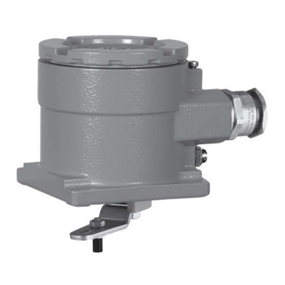
3.1 Device overview and operating controls Enclosure cover Stop screw Grounding connection (external) key key Red LED Green LED Terminal Grounding connection (internal) 10 Shaft locking Fig. 3-1: Operating controls EB 4749 EN... -
Page 16: Technical Data
Design and principle of operation 3.2 Technical data Type 4749 Position Transmitter Measuring range Measurement method Magnetoresistive measuring system Measured travel for Direct attachment to Type 3277: 3.6 to 30 mm Attachment according to IEC 60534-6 (NAMUR): 5 to 300 mm Attachment according to VDI/VDE 3847: 5 to 300 mm Attachment to rotary actuators: 24 to 100° Power supply Input voltage 12 to 36 V DC Output 4 to 20 mA · Two-wire device, reverse polarity protection... - Page 17 Complying with EN 61000-6-1, EN 61000-6-2, EN 61000-6-3, EN 61000-6-4, EN 61000-6-7, EN 61326 and NAMUR Recommen- dation NE 21 Degree of protection IP 66 Conformity Electrical connections Cable glands M20x1.5 or ½ NPT Terminals Screw terminals for 0.2 to 2.5 mm² wire cross-section Explosion protection ATEX, IECEx See ‘Summary of explosion protection approvals’ on page 3-4. Materials Enclosure and cover Die-cast aluminum EN AC-44300/EN AC-43000 according to DIN EN 1706, chromated and powder paint coated Cable glands Polyamide, nickel-plated brass Other external parts Stainless steel 1.4301/1.4310 + 1.4404/1.4409 (316 L) Weight 0.7 kg EB 4749 EN...
- Page 18 II 2 D Ex tb IIIC T80 °C Db Number IECEx KIWA 19.0022X Ex ia IIC T6…T4 Gb Ex ia IIIC T85 °C Db Date 2019-10-10 IECEx 4749-181 Ex db IIC T6…T4 Gb Ex tb IIIC T80 °C Db Number KIWA 18ATEX0036 X EC type examina- II 2 G Ex db IIC T6...T4 Gb/ 4749-210 tion certificate II 2 D Ex tb IIIC T80 °C Db Date 2018-11-11 Number IECEx KIWA 18.0017X Ex db IIC T6...T4 Gb/ IECEx 4749-211 Ex tb IIIC T80 °C Db Date 2018-11-11 EB 4749 EN...
-
Page 19: Dimensions In Mm
Design and principle of operation 3.3 Dimensions in mm EB 4749 EN... - Page 20 EB 4749 EN...
-
Page 21: Shipment And On-Site Transport
SAMSON and the forwarding agent Î Observe the storage instructions. (refer to delivery note). Î Avoid long storage times. Î Contact SAMSON in case of different 4.2 Removing the packaging storage conditions. from the position transmitter... - Page 22 If necessary, use a drying agent or heating. − Observe storage temperature depending on the permissible ambient temperature (see the 'Design and principle of opera- tion' section). − Do not place any objects on the position transmitter. EB 4749 EN...
-
Page 23: Installation
The position transmitter is suitable for the fol- The work position for the position transmitter lowing types of attachment: is the front view onto the operating controls − Direct attachment to SAMSON on the position transmitter seen from the po- Type 3277 Actuator sition of operating personnel. -
Page 24: Preparation For Installation
Fig. 5-1: Changing the pin position or quired compression of the actuator springs. exchanging the lever If a pin position other than position 35 with the standard M lever is required or a differ- ent lever size is required, proceed as follows (see Fig. 5-1): EB 4749 EN... - Page 25 Direct attachment to Type 3277-5 and Type 3277 Actuators Actuator area Rated travel Required Assigned pin lever position [cm²] [mm] 120/175/240/350 355/700/750 Attachment according to IEC 60534-6 (NAMUR rib) SAMSON valves with Type 3271 Other control Required Assigned pin Actuator valves lever position Actuator area Rated travel Max. travel [cm²]...
-
Page 26: Direct Attachment To Type 3277 And Type 3277-5 Actuators
Shaft locking with spring force. Fasten the position transmitter onto the actuator yoke using Stop screw (cover) the four fastening screws (5). 7. Mount cover (6) on the other side. Make Fig. 5-2: Shaft locking and fastening cover sure that the vent plug faces downward EB 4749 EN... - Page 27 Installation XL lever L lever M lever Mounting plate Fastening screw Fastening screw Follower clamp Fastening screw Cover Vent plug Fig. 5-3: Mounting onto Type 3277 Actuator and Type 3277-5 Actuators EB 4749 EN...
-
Page 28: Attachment According To Iec 60534-6 (Namur Rib)
6. Align the middle of the bracket to the 50 % marking on the travel indicator scale and fasten it using its screw (1) on- to the valve. EB 4749 EN... - Page 29 Installation M lever Fastening screw Bracket Bolt Follower plate XL lever L lever Follower pin Disk spring 10 Tab washer Fig. 5-4: Attachment according to IEC 60534-6 (NAMUR) EB 4749 EN...
-
Page 30: Attachment To Type 3510 Micro-Flow Valve
4. Position the bracket (3) with the position transmitter on the valve yoke and screw tight, making sure the follower pin (2) slides into the groove of the follower clamp (1). EB 4749 EN... - Page 31 Installation Follower clamp Follower pin Bracket Disk spring Lever Tab washer Fig. 5-5: Attachment to Type 3510 Micro-flow Valve EB 4749 EN...
-
Page 32: Attachment To Rotary Actuators According To Vdi/Vde 3845
90°. 6. Fasten the position transmitter onto the mounting plate (6). 7. Place the position transmitter together with the mounting plate on the top brack- 5-10 EB 4749 EN... - Page 33 Installation 1 Lever 2 Follower clamp 3 Coupling wheel 4 Bottom pair of brackets 5 Top pair of brackets 6 Mounting plate Fig. 5-6: Attachment to rotary actuators according to VDI/VDE 3845 (light version) EB 4749 EN 5-11...
-
Page 34: Heavy-Duty Version
5. Fasten coupling wheel (5) on the slotted actuator shaft or adapter (6) using screw (3) and disk spring (4). 6. Unscrew the standard follower pin from the position transmitter's M lever (1). At- tach the follower pin (Ø5 mm) included in the mounting kit to pin position 90°. 5-12 EB 4749 EN... - Page 35 Installation Lever Mounting plate Screw Disk spring Coupling wheel Adapter Enclosure Spacer Fig. 5-7: Attachment to rotary actuators according to VDI/VDE 3845 (heavy-duty version) EB 4749 EN 5-13...
-
Page 36: Establishing Electrical Connections
(U Connect the devices using suitable cable en- or I or P or C and L or L tries or conduit systems that comply with EN 60079-1 Explosive Atmospheres – Part 1: Equipment Protection by Flameproof 5-14 EB 4749 EN... - Page 37 1. Strip at least 8 mm insulation off the transmitter in the on-site equipotential signal wires and guide them through the bonding system. Use the external cable gland. grounding connection on the enclosure. 2. Connect the signal wires to the screw terminals as shown in Fig. 5-8. Î Observe the correct polarity. EB 4749 EN 5-15...
- Page 38 Installation Note The signal wires transmit the 4 to 20 mA measuring signal and the required voltage supply (U = 12 to 36 V DC) for the two-wire B transmitter. Fig. 5-8: Terminal assignment 5-16 EB 4749 EN...
-
Page 39: Mounting Accessories
Designation Order no. Attachment according to VDI/VDE 3845, level 2, heavy-duty version 1400-9974 Attachment according to VDI/VDE 3845, level 1, light version (AA1 to AA4 size) 1400-7473 Attachment according to VDI/VDE 3845, level 1, heavy-duty version (AA1 to AA4 1400-9384 size) Attachment according to VDI/VDE 3845, level 1, heavy-duty version (AA5 size) 1400-9992 Attachment for VETEC S 160/R, heavy-duty version 1400-9385 Mounting kit for Type 3277 Linear Actuators (240, 350, 700 cm²) 1400-7471 Mounting kit for Type 3271 Linear Actuators (120 cm²) 1400-7472 Mounting kit for SED diaphragm valves (both mounting kits are required) 1402-1093 1400-7472 Mounting kit for control valves with NAMUR rib or attachment to valves with rod-type 1400-7468 yokes according to IEC 60534-6 (20 to 35 mm rod diameter) Mounting kit for Type 3510 Micro-flow Valve with 60 or 120 cm² actuator area 1400-7469 EB 4749 EN 5-17... - Page 40 5-18 EB 4749 EN...
-
Page 41: Operation
Maintenance demanded Fault Selectable settings Out of specification Fig. 6-1: Operating controls of the Type 4749 Position Transmitter 6.1 Operator keys and menu structure After the power supply is connected, the green LED is illuminated constantly in the normal state (ready for operation). Press key to open the menu level. Press key once to jump to the next item within the level. - Page 42 − If no keys are pressed within five minutes, the position transmitter returns to the normal state. − When the selection level is activated, the device does not exit this level until a function or setting is made. EB 4749 EN...
-
Page 43: Locking The Configuration
The position transmitter returns to menu item 1. The green LED blinks according to the following pattern: … … Î Press key to return to the normal state. The green LED is constantly illuminated when the procedure is completed. EB 4749 EN... - Page 44 EB 4749 EN...
-
Page 45: Start-Up
Î Do not open the enclosure cover of the position transmitter in potentially explosive dust atmospheres. NOTICE Risk of malfunction due to calibration not being performed. Î Perform calibration before initial start-up. Î Calibrate the position transmitter after changing the mounting position. EB 4749 EN... -
Page 46: Determining The Mounting Situation
The green LED is constantly illuminated when the procedure is completed. 7.2 Determining the position at 4 mA The first position is assigned to the 4 mA signal. 1. Press key three times to select menu item 3. The green LED blinks according to the following pattern: … … EB 4749 EN... -
Page 47: Determining The Position At 20 Ma
The red LED illuminates for one second. The position transmitter returns to menu item 4. The green LED blinks according to the following pattern: … … 4. Press key three times to return to the normal state. The green LED is constantly illuminated when the procedure is completed. EB 4749 EN... -
Page 48: Issuing A Test Current
3. Press key to return to menu item 5. The red LED blinks according to the following pattern: … … 4. Press key twice to return to the normal state. The green LED is constantly illuminated when the procedure is completed. EB 4749 EN... -
Page 49: Operation
The position transmitter converts the linear or rotary motion of a control valve into a corresponding electric signal as soon as it is connected to the power supply. Î Put the control valve into operation by switching on the signal pressure and electrical supply. EB 4749 EN... -
Page 50: Resetting The Position Transmitter To Default Settings
3. Press key again to perform the reset function. The red LED illuminates briefly. The position transmitter returns to menu item 6. The green LED blinks according to the following pattern: … … 4. Press key to return to the normal state. The green LED is constantly illuminated when the procedure is completed. EB 4749 EN... -
Page 51: Malfunctions
WARNING Opening the position transmitter in potentially explosive dust atmospheres will render the explosion protection unsafe. Î Do not open the enclosure cover of the position transmitter in potentially explosive dust atmospheres. EB 4749 EN... - Page 52 − Defect in the electronics or memory error − The device is not running within specification Impact − Position measurement is not possible. − The residual current I ≤ 3.6 mA is issued at the output. Recommended action Î Press key to reset. Î Contact SAMSON's After-sales Service if the error message reoccurs. EB 4749 EN...
-
Page 53: Servicing
Note performed by personnel with The position transmitter was checked by qualifications according to Clause 4.5 of SAMSON before it left the factory. IEC 60079-14 who has undergone − The product warranty becomes void if special training or instructions or who is... -
Page 54: Periodic Inspection And Testing Of The Position Transmitter
Action to be taken in the event of a negative result Check the markings, labels and nameplates on Contact SAMSON when nameplates or labels are the position transmitter for their readability and damaged, missing or incorrect to renew them. completeness. -
Page 55: Decommissioning
WARNING Opening the position transmitter in potentially explosive dust atmospheres will render the explosion protection unsafe. Î Do not open the enclosure cover of the position transmitter in potentially explosive dust atmospheres. EB 4749 EN 11-1... - Page 56 11-2 EB 4749 EN...
-
Page 57: Removal
1. Put the position transmitter out of opera- tion (see the 'Decommissioning' section). 2. Disconnect the wires for the power supply from the position transmitter. 3. To remove the position transmitter, loosen the four fastening screws on the device. EB 4749 EN 12-1... - Page 58 12-2 EB 4749 EN...
-
Page 59: Repairs
Î Do not perform any repair work on your Devices that have already been operated own. outside hazardous areas and are intended Î Contact SAMSON's After-sales Service for future use inside hazardous areas must for repair work. comply with the safety requirements placed on serviced devices. Before being operated 13.1 Servicing explosion-... -
Page 60: Returning Devices To Samson
Repairs 13.2 Returning devices to SAMSON Defective position transmitters can be re- turned to SAMSON for repair. Proceed as follows to return devices to SAMSON: 1. Put the position transmitter out of opera- tion (see the 'Decommissioning' section). 2. Remove the position transmitter (see the 'Removal' section). -
Page 61: Disposal
WEEE reg. no.: DE 62194439 Î Observe local, national and internation- al refuse regulations. Î Do not dispose of components, lubricants and hazardous substances together with your other household waste. On request, we can appoint a service provider to dismantle and recycle the product. EB 4749 EN 14-1... - Page 62 14-2 EB 4749 EN...
-
Page 63: Certificates
− EU declaration of conformity for Type 4749 − EU declaration of conformity for Type 4749-111 − EU declaration of conformity for Type 4749-180 − EU declaration of conformity for Type 4749-210 − EU type examination certificate for Type 4749-110 − EU type examination certificate for Type 4749-180 − EU type examination certificate for Type 4749-210 − IECEx certificate for Type 4749-111 − IECEx certificate for Type 4749-181 − IECEx certificate for Type 4749-211 The certificates shown were up to date at the time of publishing. The latest certificates can be found on our website: u www.samsongroup.com > Products & Applications > Product selector > Valve accessories > Type 4749 EB 4749 EN 15-1... - Page 64 Management par la qualité totale Development Valve Attachments and Measurement Technologies SAMSON AKTIENGESELLSCHAFT · Weismüllerstraße 3 · D 60314 Frankfurt am Main Revision 08 Fon: +49 69 4009-0 · Fax: +49 69 4009-1507 · E-Mail: samson@samson.de · Internet: www.samson.de 15-2 EB 4749 EN...
- Page 65 Management par la qualité totale Development Valve Attachments and Measurement Technologies SAMSON AKTIENGESELLSCHAFT · Weismüllerstraße 3 · D 60314 Frankfurt am Main Revision 08 Fon: +49 69 4009-0 · Fax: +49 69 4009-1507 · E-Mail: samson@samson.de · Internet: www.samson.de EB 4749 EN 15-3...
- Page 66 Management par la qualité totale Development Valve Attachments and Measurement Technologies Revision 08 SAMSON AKTIENGESELLSCHAFT · Weismüllerstraße 3 · D 60314 Frankfurt am Main Fon: +49 69 4009-0 · Fax: +49 69 4009-1507 · E-Mail: samson@samson.de · Internet: www.samson.de 15-4 EB 4749 EN...
- Page 67 Management par la qualité totale Development Valve Attachments and Measurement Technologies SAMSON AKTIENGESELLSCHAFT · Weismüllerstraße 3 · D 60314 Frankfurt am Main Revision 08 Fon: +49 69 4009-0 · Fax: +49 69 4009-1507 · E-Mail: samson@samson.de · Internet: www.samson.de EB 4749 EN 15-5...
- Page 68 15-6 EB 4749 EN...
- Page 69 EB 4749 EN 15-7...
- Page 70 15-8 EB 4749 EN...
- Page 71 Directive 2014/34/EU KIWA 19ATEX0038 X Issue: 1 EU – Type Examination Certificate Number: Product: Position Transmitter Type 4749 Manufacturer: SAMSON AKTIENGESELLSCHAFT Weismüllerstraβe 3, 60314 Frankfurt Address: Germany This product and any acceptable variation thereto is specified in the schedule to this certificate and the documents therein referred to.
- Page 72 15.1 Description of Product The Position Transmitter Type 4749 is mounted on control valves and converts the lifting or rotating movements of the valve drive into a 4-20 mA current signal. The position transmitter enclosure is provided with a threaded cover and can be of aluminum or stainless steel.
- Page 73 Essential Health and Safety Requirements All relevant Essential Health and Safety Requirements are covered by the standards listed at section 9. Drawings and Documents As listed in ATEX Assessment Report No. 190701457. Page 3 of 3 EB 4749 EN 15-11...
- Page 74 15-12 EB 4749 EN...
- Page 75 EB 4749 EN 15-13...
- Page 76 15-14 EB 4749 EN...
- Page 77 EB 4749 EN 15-15...
- Page 78 15-16 EB 4749 EN...
- Page 79 EB 4749 EN 15-17...
- Page 80 15-18 EB 4749 EN...
- Page 81 Issue No: 0 Date of Issue: 2019-10-10 SAMSON AKTIENGESELLSCHAFT Applicant: Weismüllerstraβe 3 60314 Frankfurt Germany Position Transmitter, Type 4749 Equipment: Optional accessory: Ex i, Ex d, Ex t Type of Protection: Marking: Ex ia IIC T6…T4 Gb Ex ia IIIC T85°C Db Ex db IIC T6…T4 Gb...
- Page 82 Standards listed above. TEST & ASSESSMENT REPORTS: A sample(s) of the equipment listed has successfully met the examination and test requirements as recorded in: Test Report: NL/KIWA/ExTR19.0025/00 Quality Assessment Report: DE/TUN/QAR06.0011/08 15-20 EB 4749 EN...
- Page 83 EQUIPMENT: Equipment and systems covered by this Certificate are as follows: The Position Transmitter Type 4749 is mounted on control valves and converts the lifting or rotating movements of the valve drive into a 4-20 mA current signal. The position transmitter enclosure is provided with a threaded cover and can be of aluminium or stainless steel.
- Page 84 Supply and output circuit (terminals +31, -32): in type of protection intrinsic safety Ex ia IIC, only for connection to a certified intrinsically safe circuit, with the following maximum values: Ui = 28 V; Ii = 115 mA; Pi = 1.0 W; Ci = 19.2 nF; Li = 0 mH 15-22 EB 4749 EN...
- Page 85 EB 4749 EN 15-23...
- Page 86 15-24 EB 4749 EN...
- Page 87 EB 4749 EN 15-25...
- Page 88 15-26 EB 4749 EN...
-
Page 89: Annex
You can reach our after-sales service at aftersalesservice@samsongroup.com. Addresses of SAMSON AG and its subsid- iaries The addresses of SAMSON AG, its subsid- iaries, representatives and service facilities worldwide can be found on our website (www.samsongroup.com) or in all SAMSON product catalogs. - Page 90 16-2 EB 4749 EN...
- Page 92 EB 4749 EN SAMSON AKTIENGESELLSCHAFT Weismüllerstraße 3 · 60314 Frankfurt am Main, Germany Phone: +49 69 4009-0 · Fax: +49 69 4009-1507 samson@samsongroup.com · www.samsongroup.com...
Need help?
Do you have a question about the 4749 and is the answer not in the manual?
Questions and answers