Table of Contents
Advertisement
Quick Links
Advertisement
Table of Contents

Related Manuals for U-Prox IC L


Summary of Contents for U-Prox IC L
- Page 1 1.003 Access control panel U-Prox IC L Installation and programming manual...
- Page 2 About this document his manual covers installation, adjustment and use of U-Prox IC L (hereinafter panel) access control panel. Read this manual carefully prior to installing the system. Characteristics, Intended use and parameters of the panel are described in the section "Summary".
-
Page 3: Table Of Contents
Contents Brief description of the panel ....................4 Intended use ......................... 4 Characteristics ........................5 Terms ........................... 6 Description and operation ..................... 7 Panel ..........................7 Light emitting diodes (LED’s) ..................9 Panel operation ........................ 9 Communicator operation ....................9 Wireless lock system architecture ................ -
Page 4: Brief Description Of The Panel
Brief description of the panel U-Prox IC L control panel - a device designed to control access to residential and business premises, including time of passage and events. Panel operates U-Prox IP500 wireless battery powered escutcheons. U-Prox IC L processes the information received from the U-Prox IP500 wireless battery powered escutcheons via ISM band wireless interface. -
Page 5: Characteristics
U-Prox HE and U-Prox HW repeaters for range extention One micro USB B port for network settings configuring and firmware upgrade Isolated Ethernet port, 10BASE-T/100BASE-TX, 802.3af PoE Adjusted with U-Prox IP software. Supports automatic configuration for one-range network. Real-time clock Non-volatile memory:... -
Page 6: Terms
Terms Identifiers In access control systems each user has a unique RF ID. Identifiers can take the form of a plastic card, key FOB etc. PIN (Personal Identification Number) Some readers have built-in keypad. Keypads may be used for PIN entering. It can be both self-dependent or used as an additional code to user RF ID. -
Page 7: Description And Operation
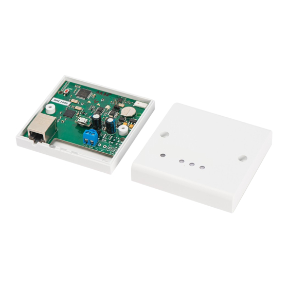
The look of the control panel is shown in Fig. 1 (a and b) The Enclosure Reset button Panel board Micro USB B port Ethernet port Connectors Figure 1a. U-Prox IC L modification 1 The Enclosure Ethernet port Micro USB B port Reset button Connectors Figure 2b. U-Prox IC L modification 2 Location of jumpers and connectors on control panel board and their function is shown in Fig. - Page 8 Figure 2a. U-Prox IC L board modification 1 Figure 2b. U-Prox IC L board modification 2 Assignment of the access control panel Contact Name Purpose +12V +12V External 12V power supply connection USB Connector For network settings configuration and...
-
Page 9: Light Emitting Diodes (Led's)
"Configurator" software and USB port or use the automatic adjustment mode. Panel goes to the “Normal” mode after uploading the configuration. To return to the factory settings use the command from the U-Prox software or with the routine described in Service Maintenance section. - Page 10 Figure 3. Mixed type (Ethernet & Wi-Fi) local network connection example...
- Page 11 Figure 4. Distributed network example It is highly recommended to use VPN technology for computer network connecting central office with sites for additional security. It is highly recommended to use routers with two different technology Internet access channels fir redundancy.
-
Page 12: Wireless Lock System Architecture
U-Prox HE and U-Prox HW repeaters. The U-Prox access control system server, U-Prox IC L, U-Prox HE and U-Prox HW communicate each other via the computer network. The U-Prox IC L, U-Prox HE and U-Prox HW communicate to the U-Prox IP500 wireless panels via the ISM band radio. - Page 13 Fig. 6. Wireless lock system deployment The algorithms for operation on each step described below Server addresses automatic configuration for U-Prox IC L Panel checks for DHCP mode ON (panel address 0.0.0.0) or static IP If DHCP mode is ON, the dynamic IP address obtain routine will start...
- Page 14 Repeater checks for DHCP mode ON (panel address 0.0.0.0) or static IP If DHCP mode is ON, the dynamic IP address obtain routine will start The panel automatic configuration mode starts if the U-Prox IC L panel IP address (IP or DNS name) is not set:...
-
Page 15: How To Work With The Device
Data packages are received with U-Prox HE repeaters and send to the U-Prox IC L control panel U-Prox IC L panel sends event message to the access control system server Access control system server warns operator about the new panel. -
Page 16: Mount Recommendations
Connect the wires Figure 8a. Fixing holes marking, modification 2 Communication U-Prox IC L uses wired computer networ for connection to the access control system server. With computer program “Configurator” the adjustment of following parameters provided: static or dynamic (DHCP) IP address assign to the panel ... -
Page 17: Wired Computer Network
Operating in the computer network U-Prox IC L control panel provides encryption protection of the data and commands with 256 bit key, unique serial number supervision and communication channel supervision with periodical test messages. Wired computer network The Ethernet interface used for device connection into the network and for device powering with PoE technology. -
Page 18: Panel Program Order
DNS server IP address, Internet gateway U-Prox IP Panel connection and enrollment in access control system software database (see U-Prox IP software instruction manual) Panel adjustment with U-Prox IP software Repeaters enrollment U-Prox IP500 wireless panels enrollment Upload panel from U-Prox IP software... -
Page 19: Service Maintenance
Service maintenance Return to factory settings To Return to factory settings: De-power control panel Press and hold FUNC button Supply power to control panel Wait for 10 seconds, until LED diode lights and release FUNC button LED diode will flash 6 times that means factory settings restored... - Page 20 Reference for device installation modification 2 --------------------------------------------------------------------------------------------------------------------...
Need help?
Do you have a question about the IC L and is the answer not in the manual?
Questions and answers