Table of Contents
Advertisement
Quick Links
Advertisement
Table of Contents

Related Manuals for technoac SUCCESS TPT-522N


Summary of Contents for technoac SUCCESS TPT-522N
-
Page 2: Table Of Contents
Table Page of Contents Introduction ......................3 1. Components and Operating Principle..............4 2. Receiver AP-027 Appearance and Controls ............5 2.1 Preparing Receiver AP-027 for operation............5 3. Acoustic sensor AD-247.................7 4. Operation sequence in liquids leak detection mode .........9 4.1 Connection of sensors and check the receiver operability ........9 4.2 Acoustic sensor AD-227 set contents ............9 4.3 Conduct fine tuning of receiver filter.............11 5. -
Page 3: Introduction
Introduction Metal and non-metal pipeline Locator with water leak detection function «Success TPT-522N»: - non-metal pipeline location underground - water leak detection from metal or non-metal pipelines underground up to 6 m depth - water leak detection inside the house - detection of cables underground up to 6 m depth - detection of any metal pipelines underground up to 6 m depth - survey the ground before the ground works ( BB mode ) -
Page 4: Components And Operating Principle
Components and Operating Principle Cable route and leak detector «Success TPT-522N» is a multi-purpose, integrated, multifunctional set. Functionally, the set joins three devices: 1. Route detector with the electromagnetic sensor; 2. Route detector with the acoustic sensor; 3. Leak detector with the acoustic sensor. -
Page 5: Receiver Ap-027 Appearance And Controls
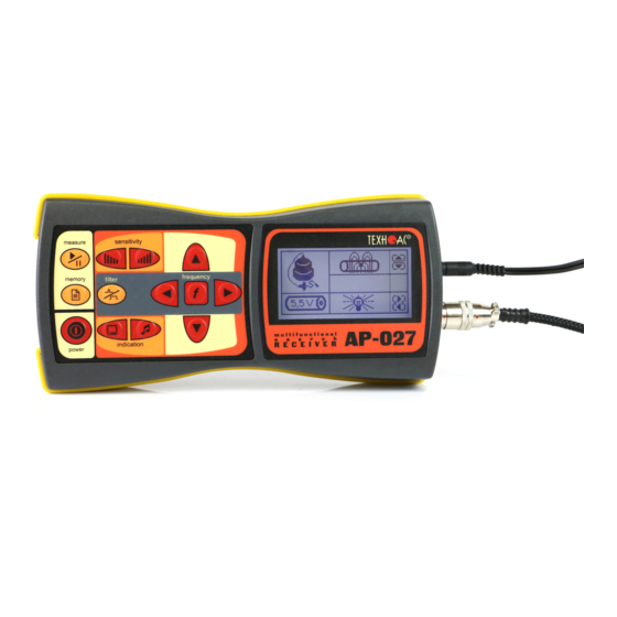
2. Receiver AP-027 Appearance and Controls Fig. 2.1 selected parameter adjustment ▲/▼ power on/off button buttons (up/down) frequency button (filter frequency visual indication type button adjustment on/off) sound indication type button LCD screen parameter selection buttons (left/ ◄/► headphones jack right) filter button (broadband on/off) sensors connector... - Page 6 2. Set the receiver on the holder 3. Put one end of the holder below protective rubber of the receiver. 4. Put other end of the holder below the second rubber 5. The receiver is ready for the operation. It is recommended to adjust the length of the neck strap for more comfort during operation.
-
Page 7: Acoustic Sensor Ad-247
3. Acoustic sensor AD-227 3.1. Set content of acoustic sensor 1 – Acoustic sensor AD-227 2 – Magnet for AD-227 3 – Contact rod for AD-227, (70 mm) 4 – Contact rod for AD-227, (150 mm) 5 – Carrying rod for AD-227 6 –... - Page 8 While working with sensor, please, make sure you are not pressing it too hard. The sensitive base may strike of vertical movement mechanical stopper. It may cause the unwanted noise in headphones and distorted signal. The distortion of signal may happen when sensitive base is placed incorrectly due to roughness of ground surface.
-
Page 9: Operation Sequence In Liquids Leak Detection Mode
4. Operation sequence in liquids leak detection mode Equipment used: Receiver Acoustic sensor Headphones Fig. 4.1 AP 027 AD-227 4.1 Connection of sensors and check the receiver operability 1. Connect acoustic sensor and headphones to the corresponding receiver connections 2. Turn on the Receiver AP-027 3.In the start window on the receiver display: Select the received... - Page 10 4.2 Preliminary route inspection Set input signal level using sensitivity buttons и Switch on the measurement mode using the button Set the broadband mode . Place the acoustic sensor over Narrow scale indicator , by pressing the supposed pipeline location readings should be preferably the filter button.
-
Page 11: Conduct Fine Tuning Of Receiver Filter
In order to enter the review mode: 1. Turn off measurement 2. Press the memory 3. Review memorized fields using the◄/► buttons mode by pressing button In order to leave memory mode press button - you enter the launch window, and then to return to the measurement mode press «start»... - Page 12 4. Conduct an analysis of the generated spectrum dark segments correspond light to the frequency to the frequency components of accidental components of valid interference (continuous) signal Frequencies where light segments prevail over the dark ones, are the most likely the interference frequencies that should be suppressed by pass band filter 6.
-
Page 13: Operation Sequence In Liquids Leak Detection Mode
5. Operation sequence in passive cable route detection mode Used equipment: receiver electromagnetic headphones AP-027 sensor EMD-247 Fig. 5.1 5.1 Connection of sensors and check of the receiver operability 2.1 To set the electromagnetic sensor from 1. Connect the electromagnetic sensor and transport to operating position. - Page 14 4. In the start window of the receiver display: Check the received signal type as «continuous» (by any of Check accuracy of the buttons ▲/▼) sensor connection. If a «no sensor» symbol If it necessary, change the is lit on the display, check frequency of the second filter if the sensor is connected correctly.
- Page 15 8. Set the required gain factor of filtered signal to «×1/2/4/8», by pressing buttons ▲/▼ 9. Commence detection or tracing according to the method set in p.4.3, avoiding prolonged input/output overloads 5.3 Route location methods 1.The Maximum method This method consists of positioning the electromagnetic sensor in the direction of the magnetic field created by the utility radiation (fig.4.3).
-
Page 16: Transmitter Ag-144.1
6. Transmitter AG-144.1 6.1 Appearance. Controls Fig. 6.1 Source (transmission, charging) switch Internal source voltage selector switch Selector switch of external source power delivery method Selector switch of transmission modes «sin» Selector switch of transmitted signal frequencies Source status and charging process indicator Output status indicator «Dangerous»... -
Page 17: Transmitter Operating Procedure
6.2 Transmitter Operating Procedure Transmitter AG-144.1 transmits sinusoidal current for electromagnetic method of route location, either continuously or as short trains, for route location of cables and metal pipelines, or impact device control pulses for acoustic route detection. High output current of the sine signal (up to 10 A) allows route location of extremely «low- resistance»... -
Page 18: Transmitter Connection
Transmitter operation mode ensuring personnel safety at disconnection from the route: -switch the transmitter off; - disconnect the output cable from the transmitter, then close the connector with a rubber plug; -repair works (digging the cable out, sleeve mounting, etc.) are allowed only AFTER the transmitter is off and disconnected from the utility. -
Page 19: Powering On The Transmitter
6.3.2 Contactless method with the use of - inductive antenna IEM-301.3 Fig.6.7 Fig.6.6 Connection to the utility is performed in inductive way. To this end, take the antenna from the package and insert the antenna active part into the base body. Connect the antenna to the transmitter output connector and install it above the place of supposed route location so that the antenna and the route are in the same plane (Fig. -
Page 20: Transmitter Parameter Setting
6.5 Transmitter parameter setting 6.5.1 Open the cover. Using selector switch «FREQ» (Pt. 5, Fig Fig 6.8), select the required frequency of sinusoidal transmission (512/1024/8192 Hz). 6.5.2 Using selector switch «MODE SIN» (Pt. 4, Fig 6.8), select the required type of sinusoidal transmission («CONT»/«... -
Page 21: Changing The Set Transmitter Parameters
NOTE. Operation duration in shock mode when powered from the autonomous source only at the 12 V supply voltage is twice as long as at the 24 V voltage (with the shock repetition rate being the same). The external source prolongs the operation duration and/or increases the shock force. When working in the shock mode, just as when using any mechanical shock device, remember that you are responsible for possible damages of pipes. -
Page 22: Internal Accumulators Charge
Namely: - External accumulator is used for power supply life prolongation, with the selector switch «SOURCE EXTERN ACC» set to position «II»; - external accumulator is used for power supply life prolongation, with the selector switch «SOURCE EXTERN ACC» set to position «+» and net supply voltage (Σ) of 24 V; - external accumulator is used for power supply life prolongation and/or power/impact strength increase (at Uextern acc=12V-powerx1.5, at Uextern acc=24V-powerx1.5 and lifex2), with the selector switch «SOURCE EXTERN ACC»... - Page 23 6.11 Internal accumulators charge Necessary instruments for charge is given on a figure 6.2: Transmitter External power supply unit AG-144.1 ESP-120-13.5 Charger connection cable Power supply cable AG-144.02.030 Fig. 6.2 Charger connection scheme is given on a figure 6.3: SOCKET of to 220V DC EXTERNAL POWER Fig.
- Page 24 In order to start the charge of accumulators, connect the charger and transmitter as given above: 1. With red-black cable (AG-144.02.030) connect transmitter on EXTERNAL POWER socket on one end and to the corresponding leads of ESP 120-13.5 on the other. 2.
-
Page 25: Active Route Detection
7 Active Route Detection 7.1 Incorporated equipment 1 – Receiver AP-027 2 – Transmitter AG-144.1 3 – Acoustic sensor AD-227 4 – Electromagnetic sensor EMD-247 5 – Headphones 6 – Inductive antenna IEM - 301.3 7 – Impact device UM - 112 At present the inductive (active) detection method has found the widest application in detection of underground utilities. - Page 26 Turn on the transmitter. Set the signal mode – continuous or pulse. Set transmitted frequency: 512 Hz / 1024 Hz / 8192 Hz 3.Using the button power on the Receiver AP-027. 4. In the «start» window of the receiver display check the following: Select received signal type - «continuous Accuracy of sensor...
- Page 27 Set input signal level Exit filter adjustment mode by using «sensitivity» buttons pressing the «frequency» button ). In the window zone of the display, the prompt message will disappear and then reappear in a different zone Set sound mode: natural synthesized via headphones /synthesized via built-in speaker...
-
Page 28: Operation Sequence In Acoustic Cable Route Detection Mode
7.3 Operation sequence in acoustic route detection mode Incorporated equipment (Fig. 5.10): Route locating transmitter AG-144.1 Inductive antenna IEM-301.2; Receiver AP-027; Acoustic sensor - AD-227; Headphones; Impact device UM-112. Attention! It is obligatory to fix firmly the impact device UM-112 on the pipe before switching it on. - Page 29 7.3.3 Switch the transmitter on When energized, the transmitter switches over to «IMPACT» mode (Pt.5, Fig. 7.8) automatically, where one of the three repetition rates of impact pulses (20-40-80 impacts per minute) can be selected, and the impact force is directly proportional to the supply voltage. 7.3.4 Using the selector switch «SOURCE INTERN»...
-
Page 30: In Direct Electromagnetic Mode Of Measuring Depth
8 In direct electromagnetic mode of measuring depth Connect the electromagnetic sensor to the connectors ofthe Receiver AP-027.When determining the depth, one should take into account the terrain. In order to obtain precise results, select flat surface areas. Find the precise pipeline route location (preferably using the minimum method).Mark the spot. -
Page 31: Receiver Ap-027. Technical Specifications
Appendix A Receiver AP-027. Technical specifications Parameter Tracing Leak detection Type of accepted signal Uninterrupted /pulse Uninterrupted signal Range limitation Central frequency of quasi- “below” resonant filter 50..60 Hz,100….450 0,1/0,15/0,21/0,31/0,45/0,65/0,95/1, Frequencies of the receiver’s Hz through 50 Hz, 38 kHz filter 120…540 Hz through 60 Hz, Range limitation... -
Page 32: Technical Characteristics Of The Transmitter
Technical Characteristics of the Transmitter Transmitted signal frequencies, Hz Frequencies SIN f1 / f2 / f3, ±0.1% 512 / 1024 / 8192 Shock repetition frequencies, low/medium/high 0.5 / 1 / 2 frequency Transmission modes «SIN» «contin» Continuous sine transmission Short-time pulsing of sine signal SIN»... - Page 33 Network unit for accumulators operation or charging Output voltage 15 V, output current up to 6.7 A Source duration depending on power that was initially gained as a result of self-matching (ambient temperature 0 С), minimum continuous generation Duration, hours Pout, W autonomously/90 30 autonomously/45 with add.
- Page 34 Types of connected loads at transmission - direct connection to the facility with current «return» "SIN" via the cable cord or armature - direct connection to the facility with current «return» via ground by means of a ground pin - loop connection with the use of the transmitting loop antenna at the 8192 Hz (selected automatically at antenna connection) - loop connection with the use of the loop clamp...
-
Page 35: Control And Indication Of The Generator Ag-144.1
Appendix B Control and indication of the generator AG-144.1 1 Source Status and Charging 2 Output Status Indicator. 3«Dangerous» Mode Process Indicator. Faded – not transmission (pause, Field. Continuous light colour: charging or automatic switching off due If the red button is held pressed - green –normal source or the 2nd to improper source). -
Page 37: Receiver Ap-027. Indication
Appendix C Receiver AP-027. Indication 1. Switching-on the receiver When the receiver is switched on, the display shows the following sequence: manufacturer’s trademark (logo) «TECHNO-AC», Business card of the Receiver AP-027 (fig.B.1) and the Start window (fig.B.2). Fig. В.1 2. The start window type of the sensor type of signal received connected... - Page 38 3. Scale window When measurement mode is selected (except the two-frequency), Scale working window appears first fig.А.3. Filtering Displays the frequency range scales with numerical and graphical representation of the pass band During work with AD: - pass band filter - broadband During work with EMD: - central frequency of the...
- Page 39 4. Graph window The graph displays the changes in processed signal levels over time and moves at constant speed from right to left. The graph shows processed signal - in mode - change in the level of processed valid signal over time - in modes - change in the level of current signal value over time Narrow scale...
- Page 40 6. Power range spectrum window The window is available in the electromagnetic mode of broadband and can be called for by the additional touch of a button . The display shows the industrial frequency spectrum of «10 ... 640 Hz». Maximum of emission spectrum of the power cable falls to 50/60 Hz.
- Page 41 9. Audio indication The sound is output to the headphones or the built-in sound transmitter. Three categories of sound are used: - «Natural» without filtering (broadband) to the phones; - «Natural» filtered (narrowband) to the phones; - «Synthetic» (modulation of sound frequency by the level of the filtered signal) to the phones or to the built-in transmitter.
Need help?
Do you have a question about the SUCCESS TPT-522N and is the answer not in the manual?
Questions and answers