Table of Contents
Advertisement
Quick Links
Advertisement
Table of Contents

Subscribe to Our Youtube Channel
Related Manuals for TiePie Handyscope TP450


Summary of Contents for TiePie Handyscope TP450
- Page 1 Handyscope TP450 User manual TiePie engineering...
- Page 2 Copyright ©2020 TiePie engineering. All rights reserved. Revision 2.27, February 2020 Despite the care taken for the compilation of this user man- ual, TiePie engineering can not be held responsible for any damage resulting from errors that may appear in this man- ual.
-
Page 3: Table Of Contents
Contents Safety Declaration of conformity Introduction Differential input ......3.1.1 Differential test lead ....Sampling . - Page 4 Physical ....... . . I/O connectors ......System requirements .
- Page 5 Do not use the equipment if it does not operate properly. Have the equip- ment inspected by qualified service personal. If necessary, return the equip- ment to TiePie engineering for service and repair to ensure that safety fea- tures are maintained.
-
Page 7: Declaration Of Conformity
8601 WL Sneek The Netherlands EC Declaration of conformity We declare, on our own responsibility, that the product Handyscope TP450-250(XM) Handyscope TP450-50(XM) for which this declaration is valid, is in compliance with EC directive 2011/65/EU (the RoHS directive) including up to amendement 2019/178,... - Page 8 In order to avoid release of such substances into the environment and to reduce the use of natural resources, recycle the Handyscope TP450 in an appropriate system that will ensure that most of the materials are reused or recycled appro- priately.
-
Page 9: Introduction
1 MiSa Table 3.2: Maximum record length per channel With the accompanying software the Handyscope TP450 can be used as an os- cilloscope, a spectrum analyzer, a true RMS voltmeter or a transient recorder. All instruments measure by sampling the input signals, digitizing the values, process them, save them and display them. - Page 10 Figure 3.1: Single ended input Therefore the voltage that is measured with an oscilloscope with standard, single ended inputs is always measured between that specific point and ground. When the voltage is not referenced to ground, connecting a standard single ended oscilloscope input to the two points would create a short circuit between one of the points and ground, possibly damaging the circuit and the oscilloscope.
-
Page 11: Differential Test Lead
The Handyscope TP450 is galvanically isolated. This means that there is no elec- trical connection between the inputs and the USB connection. It is therefore not possible to damage the connected computer when (accidentally) making a wrong connection. -
Page 12: Sampling Rate
Figure 3.3: Sampling The sine wave in figure is sampled at the dot positions. By connecting the adjacent samples, the original signal can be reconstructed from the samples. You can see the result in figure 3.4. Figure 3.4: ”connecting” the samples Sampling rate The rate at which the samples are taken is called the sampling rate, the number of samples per second. -
Page 13: Aliasing
Figure 3.5: The effect of the sampling rate The sampling rate must be higher than 2 times the highest frequency in the input signal. This is called the Nyquist frequency. Theoretically it is possible to recon- struct the input signal with more than 2 samples per period. In practice, 10 to 20 samples per period are recommended to be able to examine the signal thor- oughly. -
Page 14: Digitizing
Figure 3.6: Aliasing In figure 3.6, the green input signal (top) is a triangular signal with a frequency of 1.25 kHz. The signal is sampled with a rate of 1 kSa/s. The corresponding sam- pling interval is 1/1000Hz = 1ms. The positions at which the signal is sampled are depicted with the blue dots. -
Page 15: Signal Coupling
V. This results in a smallest detectable voltage step of 4 V / 65536 = 61.0 µV. Signal coupling The Handyscope TP450 has two different settings for the signal coupling: AC and DC. In the setting DC, the signal is directly coupled to the input circuit. All signal components available in the input signal will arrive at the input circuit and will be measured. - Page 16 Chapter 3...
-
Page 17: Driver Installation
Computers running Windows 10 When the Handyscope TP450 is plugged in into a USB port of the computer, Win- dows will detect the instrument and will download the required driver from Win- dows Update. When the download is finished, the driver will be installed automat- ically. - Page 18 When drivers were already installed, the install utility will remove them before in- stalling the new driver. To remove the old driver successfully, it is essential that the Handyscope TP450 is disconnected from the computer prior to starting the driver install utility.
- Page 19 Figure 4.3: Driver install: Finished Driver installation...
- Page 20 Chapter 4...
-
Page 21: Hardware Installation
Power the instrument The Handyscope TP450 is powered by the USB, no external power supply is re- quired. Only connect the Handyscope TP450 to a bus powered USB port, other- wise it may not get enough power to operate properly. - Page 22 Chapter 5...
-
Page 23: Input Connnectors
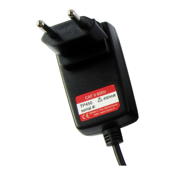
The CH1 slide contact connectors are the inputs of the acquisition system. The Handyscope TP450 is delivered with four different mains wall socket adapters, which can be placed on the instrument body. The Handyscope TP450 can then be plugged in a matching wall socket to measure the mains voltage directly. - Page 24 Chapter 6...
-
Page 25: Specifications
Specifications Acquisition system Number of input channels 1 analog Connector 2 slide contacts Type galvanically isolated differential Resolution 16 bit Amplitude Accuracy 0.5% of full scale Ranges (full scale) ±2 V ±20 V ±200 V ±4 V ±40 V ±400 V ±8 V ±80 V ±450 V... -
Page 26: Interface
Interface Interface USB 2.0 High Speed (480 Mbit/s) (USB 1.1 Full Speed and USB 3.0 compatible) Power Power from USB port Consumption , 100 mA max Physical Instrument height 70 mm / 2.75” Instrument length 72 mm / 2.83” Instrument width 42 mm / 1.65”... - Page 27 Heat resistant Certification and compliances CE conformity RoHS Accessories Color coding rings 5 x 3 rings, various colors Suitable instrument Handyscope TP450 7.11 Package contents Instrument Handyscope TP450 Test lead low noise differential with 4 mm banana plugs Accessories 2 test probes with 4 mm banana socket...
- Page 28 Chapter 7...
- Page 29 If you have any suggestions and/or remarks regarding this manual, please contact: TiePie engineering Koperslagersstraat 37 8601 WL SNEEK The Netherlands Tel.: +31 515 415 416 Fax: +31 515 418 819 E-mail: support@tiepie.nl Site: www.tiepie.com...
- Page 30 TiePie engineering Handyscope TP450 instrument manual revision 2.27, February 2020...
Need help?
Do you have a question about the Handyscope TP450 and is the answer not in the manual?
Questions and answers