TiePie Handyscope HS4 User Manual
Hide thumbs
Also See for Handyscope HS4:
- Programmer's manual (67 pages) ,
- Instrument manual (41 pages) ,
- User manual (36 pages)
Table of Contents
Advertisement
Quick Links
Advertisement
Table of Contents

Subscribe to Our Youtube Channel
Related Manuals for TiePie Handyscope HS4


Summary of Contents for TiePie Handyscope HS4
- Page 1 Handyscope HS4 User manual TiePie engineering...
- Page 2 Use a good isolation transformer or a dif- ferential probe when measuring at the line voltage or at grounded power supplies! A short-circuit current will flow if the ground of the Handyscope HS4 is connected to a positive voltage. This short-circuit current can damage both the Handyscope HS4 and the computer.
-
Page 3: Table Of Contents
Contents Safety Declaration of conformity Introduction Sampling ....... . Sampling rate . - Page 4 ........Extension Connector ......Specifications Acquisition system .
- Page 5 Do not use the equipment if it does not operate properly. Have the equip- ment inspected by qualified service personal. If necessary, return the equip- ment to TiePie engineering for service and repair to ensure that safety fea- tures are maintained.
-
Page 7: Declaration Of Conformity
Koperslagersstraat 37 8601 WL Sneek The Netherlands EC Declaration of conformity We declare, on our own responsibility, that the product Handyscope HS4-5MHz Handyscope HS4-10MHz Handyscope HS4-25MHz Handyscope HS4-50MHz for which this declaration is valid, is in compliance with EC directive 2011/65/EU (the RoHS directive) - Page 8 In order to avoid release of such substances into the environment and to reduce the use of natural resources, recycle the Handyscope HS4 in an appropriate sys- tem that will ensure that most of the materials are reused or recycled appropri- ately.
-
Page 9: Introduction
48 kSa/s Table 3.2: Maximum streaming rates With the accompanying software the Handyscope HS4 can be used as an oscil- loscope, a spectrum analyzer, a true RMS voltmeter or a transient recorder. All instruments measure by sampling the input signals, digitizing the values, process them, save them and display them. -
Page 10: Sampling Rate
the smaller the voltage steps in which the input range of the instrument is divided. The acquired numbers can be used for various purposes, e.g. to create a graph. Figure 3.1: Sampling The sine wave in figure is sampled at the dot positions. By connecting the adjacent samples, the original signal can be reconstructed from the samples. -
Page 11: Aliasing
Figure 3.3: The effect of the sampling rate The sampling rate must be higher than 2 times the highest frequency in the input signal. This is called the Nyquist frequency. Theoretically it is possible to recon- struct the input signal with more than 2 samples per period. In practice, 10 to 20 samples per period are recommended to be able to examine the signal thor- oughly. -
Page 12: Digitizing
Figure 3.4: Aliasing In figure 3.4, the green input signal (top) is a triangular signal with a frequency of 1.25 kHz. The signal is sampled with a rate of 1 kSa/s. The corresponding sam- pling interval is 1/1000Hz = 1ms. The positions at which the signal is sampled are depicted with the blue dots. -
Page 13: Signal Coupling
When measuring DC signals, make sure to set the signal coupling of the input to DC. Probe compensation The Handyscope HS4 is shipped with a probe for each input channel. These are 1x/10x selectable passive probes. This means that the input signal is passed through directly or 10 times attenuated. - Page 14 When using an oscilloscope probe in 1:1 the setting, the bandwidth of the probe is only 6 MHz. The full bandwidth of the probe is only obtained in the 1:10 setting The x10 attenuation is achieved by means of an attenuation network. This atten- uation network has to be adjusted to the oscilloscope input circuitry, to guaran- tee frequency independency.
-
Page 15: Driver Installation
Computers running Windows 10 When the Handyscope HS4 is plugged in into a USB port of the computer, Win- dows will detect the instrument and will download the required driver from Win- dows Update. When the download is finished, the driver will be installed automat- ically. - Page 16 To remove the old driver successfully, it is essential that the Handyscope HS4 is disconnected from the computer prior to starting the driver install utility. When the Handyscope HS4 is used with an external power supply, this must be disconnected too.
- Page 17 Figure 4.3: Driver install: Finished Driver installation...
- Page 18 Chapter 4...
-
Page 19: Hardware Installation
In order to power the Handyscope HS4 externally, an external power input is pro- vided for. It is located at the rear of the Handyscope HS4. Refer to paragraph for specifications of the external power intput. - Page 20 Chapter 5...
-
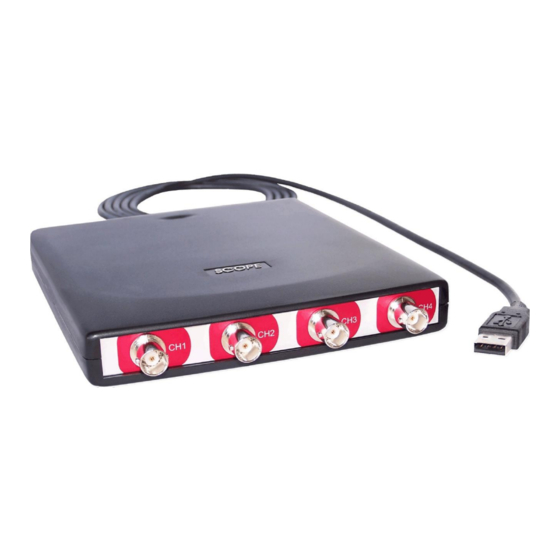
Page 21: Front Panel
HS4. Connecting the outside of the BNC connector to a potential other than ground will result in a short circuit that may damage the device under test, the Handyscope HS4 and the computer. Power indicator A power indicator is situated at the top cover of the instrument. It is lit when the Handyscope HS4 is powered. - Page 22 Chapter 6...
-
Page 23: Rear Panel
Figure 7.1: Rear panel Power The Handyscope HS4 is powered through the USB. If the USB cannot deliver enough power, it is possible to power the instrument externally. The Handyscope HS4 has two external power inputs located at the rear of the instrument: the dedicated power input and a pin of the extension connector. -
Page 24: Power Adapter
The Handyscope HS4 is equipped with a USB 2.0 High speed (480 Mbit/s) interface with a fixed cable with type A plug. It will also work on a computer with a USB 1.1 interface, but will then operate at 12 Mbit/s. -
Page 25: Extension Connector
Extension Connector Figure 7.4: Extension connector To connect to the Handyscope HS4 a 25 pin female D-sub connector is available, containing the following signals: Description Description Ground Ground Reserved Ground External Power in DC Reserved Ground Ground +5V out, 10 mA max. - Page 26 Chapter 7...
-
Page 27: Specifications
Specifications Acquisition system Number of input channels 4 analog CH1, CH2, CH3, CH4 Type Single ended Resolution 12, 14, 16 bit user selectable 0.2% of full scale ± 1 LSB Accuracy Ranges (full scale) ±200 mV ±400 mV ±800 mV ±2 V ±4 V ±8 V... -
Page 28: Trigger System
Trigger system System digital, 2 levels Source CH1, CH2, CH3, CH4, digital external, AND, OR Trigger modes rising slope, falling slope, inside window, outside window Level adjustment 0 to 100% of full scale Hysteresis adjustment 0 to 100% of full scale Resolution 0.024 % (12 bits) Pre trigger... -
Page 29: Environmental Conditions
300 V 600 V 150 V CAT II 300 V CAT II 8.11 Package contents Instrument Handyscope HS4 Probes 4 x HP-3060 X1 / X10 switchable Accessories USB power cable Software Windows 10, 32 and 64 bits, via website Drivers... - Page 30 Chapter 8...
- Page 31 If you have any suggestions and/or remarks regarding this manual, please contact: TiePie engineering Koperslagersstraat 37 8601 WL SNEEK The Netherlands Tel.: +31 515 415 416 Fax: +31 515 418 819 E-mail: support@tiepie.nl Site: www.tiepie.com...
- Page 32 TiePie engineering Handyscope HS4 instrument manual revision 2.27, February 2020...
Need help?
Do you have a question about the Handyscope HS4 and is the answer not in the manual?
Questions and answers