
Related Manuals for MasterForce 260-9513


Summary of Contents for MasterForce 260-9513
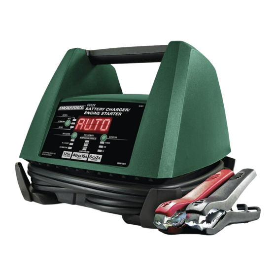
- Page 1 125A Automatic Battery Charger & Engine Starter 260-9513 To Reduce The Risk Of Injury, User Must Read And Understand Operator’s Manual. Save These Instructions For Future Reference. 0099002180-01...
-
Page 2: Table Of Contents
TABLE OF CONTENTS Safety Symbols ................Page 3 Safety Information ................Page 4 Important Safety Instructions ............Page 5 Personal Safety Precautions............Page 5 Preparing To Charge ...............Page 6 Charger Location ................Page 6 DC Connection Precautions ............Page 6 Follow These Steps When Battery Is Installed In Vehicle ....Page 6 Follow These Steps When Battery Is Outside Vehicle ....Page 7 Grounding and AC Power Cord Connections ......Page 7 Assembly Instructions ..............Page 8... -
Page 3: Safety Symbols
SAFETY SYMBOLS Some of the following symbols may be used on your charger. Please study them and learn their meaning. Proper interpretation of these symbols will allow better and safer operation of the charger. Symbol Name Designation/Explanation Volts Voltage Amperes Current Hertz Frequency... -
Page 4: Safety Information
SAFETY INFORMATION The purpose of safety symbols is to attract our attention to possible dangers. The safety symbols, and the explanations with them, deserve your careful attention and understanding. The symbol warnings do not by themselves eliminate any danger. The instructions and warnings they give are no substitutes for proper accident pre- vention measures. -
Page 5: Important Safety Instructions
1. IMPORTANT SAFETY INSTRUCTIONS 1.1 SAVE THESE INSTRUCTIONS – This or otherwise damaged in any way; manual contains important safety and take it to a qualified serviceman. operating instructions. 1.8 Do not disassemble charger; take it 1.2 Do not expose the charger to rain or to a qualified serviceman when ser- snow. -
Page 6: Preparing To Charge
produce a short-circuit current high a starter-motor application. Do not use enough to weld a ring or the like to battery charger for charging dry-cell metal, causing a severe burn. batteries that are commonly used with home appliances. These batteries may 2.8 Use the charger for charging only 6V burst and cause injury to persons and and 12V LEAD-ACID (STD, GEL or... -
Page 7: Follow These Steps When Battery Is Outside Vehicle
6.3 Check polarity of battery posts. POS- 6.6 For positive-grounded vehicle, con- ITIVE (POS, P, +) battery post usually nect NEGATIVE (BLACK) clip from has larger diameter than NEGATIVE battery charger to NEGATIVE (NEG, (NEG, N,–) post. N, –) ungrounded post of battery. Connect POSITIVE (RED) clip to 6.4 Determine which post of battery is vehicle chassis or engine block away... -
Page 8: Assembly Instructions
8.3 USING AN EXTENSION CORD • Ensure that the extension cord is properly wired and in good electri- The use of an extension cord is not cal condition. recommended. If you must use an • Wire size must be large enough for extension cord, follow these guidelines: the AC ampere rating of charger, •... -
Page 9: Operating Instructions
BATTERY TYPE BUTTON recharge efficiency. The AGM batter- ies are a variant of Sealed VRLA (valve Use this button to set the type of battery. regulated lead-acid) batteries. Popular NOTE: Each of the three settings apply for uses include high-performance engine regular and deep-cycle batteries. - Page 10 AC outlet, connect the charger to the MAINTAINING A BATTERY battery, following the instructions given The 260-9513 maintains 6 and 12 volt bat- in sections 6 and 7. teries, keeping them at full charge. It is not 2. With the charger plugged in and con- recommended for industrial applications.
- Page 11 USING THE BATTERY press the Rate Selection button until the Engine Start LED is lit. VOLTAGE TESTER 1. With the charger unplugged from the 3. When the display shows ENGINE START READY, crank the engine until AC outlet, connect the charger to the it starts or 3 seconds pass.
-
Page 12: Display Messages
USING THE ALTERNATOR NOTE: Refer to your vehicle owner’s man- ual for appropriate voltage numbers for PERFORMANCE TESTER your alternator. 1. With the charger unplugged from the AC outlet, connect the charger to the FAN OPERATION battery, following the instructions given It is normal for the fan to start and stop in previous sections. -
Page 13: Maintenance And Care
13. MAINTENANCE AND CARE A minimal amount of care can keep your • Coil the input and output cords neatly battery charger working properly for years. when storing the charger. This will help prevent accidental damage to the cords • Clean the clamps each time you are and charger. -
Page 14: Specifications
PROBLEM POSSIBLE CAUSE SOLUTION Yellow/orange CHARGING The battery is sulfated. Reset the charger by briefly LED is flashing and the unplugging it. display shows CHARGE The battery is too large for You need a charger with a ABORTED BAD BATTERY. the charger. -
Page 15: Warranty
® discretion, MASTERFORCE™ agrees to have the item or any defective part(s) repaired or replaced with the same or similar MASTERFORCE™ product or part free of charge, within the stated warranty period, when returned by the original purchaser with original sales receipt. Not withstanding the foregoing, this limited warranty does not cover any damage that has resulted from abuse or misuse of the Merchandise. - Page 16 © 2020 Menard, Inc., Eau Claire, WI 54703 06/2020...
Need help?
Do you have a question about the 260-9513 and is the answer not in the manual?
Questions and answers