
Subscribe to Our Youtube Channel
Related Manuals for Kemper KHS MASTER

Summary of Contents for Kemper KHS MASTER
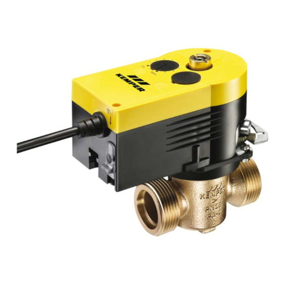
- Page 1 Installation and operating instructions KEMPER KHS Mini System Control KEMPER KHS Mini System Control MASTER Figure 686 02 005 KHS Mini System Control SLAVE Figure 686 02 006...
-
Page 2: Table Of Contents
TABLE OF CONTENTS GENERAL INSTRUCTIONS: ........................ 1 AREA OF APPLICATION ........................2 Operating modes for the water exchange ............... 2 KHS MASTER/SLAVE technology ..................2 Water exchange groups ..................... 2 SAFETY ............................. 3 Safety Instructions ......................3 Hazards if the safety instructions are not complied with ..........3 Unauthorized alteration and spare part fabrication ............ - Page 3 CONFIGURATION ........................16 8.1.1 Basic menu operation and functions ..................17 8.1.2 General plan ........................... 18 8.1.4 Main menu ............................. 20 8.1.4.1 System settings ..........................21 8.1.4.2 CAN BUS setup ..........................24 8.1.4.3 Device settings ..........................25 8.1.4.4 Operating modes ......................... 28 8.1.4.5 Journal ............................
-
Page 4: General Instructions
General instructions: Assemble and commission the KEMPER KTS Mini System Control only after reading these assembly and operating instructions. It informs you in detail about the assembly, commissioning, operating principles and operation of the Kemper KHS Mini System Control. If you cannot find the information and instructions you need in these operating instructions, ask the manufacturer, Gebr. -
Page 5: Area Of Application
Area of application The KEMPER KHS Mini System Control can be used for monitoring and water exchange in drinking water systems. The water exchanges can be generated and documented as flushing logs with the -MASTER- control. The dedicated water exchanges prevent stagnation in the drinking water with the aim of maintaining the drinking water hygiene in the drinking water systems. -
Page 6: Safety
Safety Warning notice: During assembly The descriptions and instructions in maintenance, make sure that these operating instructions concern the control is not switched on. Mini System Control -MASTER- Mini System Only skilled professional Control -SLAVE-. personnel permitted operate electrical systems (as per DIN EN 50110-1). -
Page 7: Technical Data
Technical Data Technical Data Power supply 230 V AC 50/60Hz Display Graphic display with background lighting Operation with 4 buttons: Up | Down | Enter | Esc Relay flush valve switching capacity 230 V, 2 A ... -
Page 8: Can Bus System Overview
CAN bus system overview The basic version of the -MASTER- control system includes as the smallest solution a flushing valve for water exchanging measures. This -MASTER- System Control is required for triggering the flushing valve and for signal evaluation. Up to a maximum of 31 -SLAVE- controls per CAN-BUS connection of the -MASTER- can be controlled per CAN bus connection. -
Page 9: Terminal Resistance
Example 2: Incorrect layout CAN bus Note: Incorrect layout Ill. 5.2 View of an impermissible layout variant, KHS Mini System Control -Master- Terminal resistance Variant 1 Note: Ω terminal resistance must be installed only last control component (-SLAVE-) of a CAN bus cable line. -
Page 10: Assembly
Assembly Warning notice: Allow only certified electricians to assemble and install electrical equipment. Danger of fatal electric shock. Very strong magnetic fields can impair the functioning. Interferences can be prevented by following the installation rules below: Do not mount the controller and the sensors near inductive loads (motors, transformers, contactors, etc.). -
Page 11: Electrical Installation Khs Mini System Control
Electrical installation KHS Mini System Control The following chapter explains the electrical installation. The electrical connections are made through screwless-type terminals. 6.2.1 Terminal description -MASTER- and -SLAVE- Illustration: Control board with terminals 1. Flushing valve switching output 230 ________________________ 2. Flushing valve voltage output 230 V (only on 68604) ___________ 3. -
Page 12: 2Detailed Illustration Of The Terminals For Cable Entry
6.2.2 Detailed illustration of the terminals for cable entry Note: The following illustrations apply to the KHS Mini System Control -MASTER- and the KHS Mini System Control -SLAVE-. Please note the preceding warning notices. 6.2.2.1 Power supply connection Power supply: 230 V +/- 15% AC 50/60Hz Connection: Terminals, L, N, PE Line fuse max. -
Page 13: 3Connection Of Khs Isolating Valve With Spring Reset Servo-Drive (Figure 686 01)
6.2.2.3 Connection of KHS Isolating valve with spring reset servo-drive (Figure 686 05 / 686 15 / 696 05) BN = brown = 1 BU = blue = 3 Ill. 6.5: Schematic representation of the connection of the KHS Isolating valve with spring reset servo-drive 6.2.2.4 CAN bus connection... -
Page 14: 5Connection Of External Switch
terminal groups 8/9/10 CAN bus H and L = 1 Put on GND cable 11/12/13 are of equal value. For Twisted-Pair shielding instance the wire end a can also be H: Strand 1 connected to Terminals 11/12/13 and L: Strand 2 the wired end to Terminals 8/9/10. -
Page 15: 6Connection Of Khs-Control-Plus Flow Measurement Valve (Figure 638 4G)
6.2.2.6 Connection of KHS-CONTROL-PLUS flow measurement valve (Figure 638 4G / 138 4G) Connection of KHS-CONTROL-PLUS volume flow measurement valve 14 15 17 BR = +5V DC = 14 BU = Flow = 15 BK = GND = 17 Ill. 6.9: Schematic diagram of connection of KHS-CONTROL-PLUS flow measurement valve Connection of KHS-CONTROL-PLUS temperature sensor Attention:... -
Page 16: 7Connection Of Khs Temperature Sensor Pt 1000 (Figure 628 0G)
Connection of KHS-CONTROL-PLUS cable-plug connector 1. Cut off top of cap 2. Route cable through 3. Screw cable to sensor 4. Put on the Ill. 6.12: Schematic diagram of the preparation of the sensor top to make cable- plug connection of the KHS-CONTROL-PLUS 6.2.2.7 Connection of KHS Temperature sensor Pt 1000 (Figure 628 0G) RD = red = 18... -
Page 17: 9Connection Of Water Sensor (Figure 620 00)
6.2.2.9 Connection of water sensor (Figure 620 00) Note: It is possible to link up to 25 water sensors in parallel in the detection circuit. Max. cable length water sensor: < 50m with standard cable Max. cable length water sensor: >... -
Page 18: Commissioning
Commissioning After finishing the wall installation and the electrical installation in accordance with Chapter 5, apply the mains voltage of 230V. Warning notice: Allow only certified electricians to assemble and install electrical equipment. Danger of fatal electric shock. ATTENTION! Note: To simplify the control system and to guarantee flawless installation, fill in the overview of the system commissioning of the KHS Mini System Control (see supply pressure, Chapter 13.2) before making the... -
Page 19: Configuration
Configuration The KHS Mini System Control -MASTER- can be configured through the internal menu driven operation or through a web server. Furthermore, the saved configurations can be uploaded through a USB interface to the KHS Mini System Control -MASTER-. The sample project shown below shows the basic controller types of the KHS Mini System Control -MASTER-. -
Page 20: 8.1.1 Basic Menu Operation And Functions
Manual configuration Basic settings, configurations and changes can be made onsite by using the integrated menus. In the following chapter, the menu interfaces and their functions are clarified. To explain the settings and functions, the sample project is configured as a reference building. -
Page 21: 8.1.2 General Plan
8.1.2 General plan The following illustrations explain the "General plan" menu interface of the KHS Mini System Control -MASTER-. The illustrations show the "General plan" based on an exemplary configuration of a system with one KHS Mini System Control -MASTER- and two KHS Mini System Controls -SLAVE-. - Page 22 8.1.3 Detailed overview The following illustrations clarify the "Detailed overview" menu interface of the KHS Mini System Control -MASTER-. The illustrations show the "Detailed overview" based on an exemplary configuration of a system with one KHS Mini System Control -MASTER- and two KHS Mini System Controls -SLAVE-.
-
Page 23: 8.1.4 Main Menu
8.1.4 Main menu The following chapters explain the functions of the "Main menu" interface of the KHS Mini System Control -MASTER-. In the main menu there are the sub-menus: System settings, Can-bus setup, Device settings, Operating modes, Journal, Switch program, Valve manual mode, Network setup (see Ill. -
Page 24: System Settings
8.1.4.1 System settings In the "System settings" menu interface, settings for the date / time, language daylight savings/standard time, alarm buzzer, button acknowledgement, display lighting, display contrast, password, factory settings and system reboot can be made. Language In the system control submenu select the menu item "Language" with "OK"; press "OK" again to store the selected language and to open the system control submenu again. - Page 25 Alarm buzzer If an error occurs in the system controllers, it can be acoustically reported. To activate this function, select the menu item "Alarm buzzer" in the system control submenu with "OK". Pressing "OK" again saves the selected setting; the system control submenu opens again.
- Page 26 Password To protect the controller from interference, a password can be configured. If a password has been stored, the password will be queried before every setting (see Ill. 8.19). To do that, select the "Password" menu item in the system control submenu with "OK". Use the "↑"...
-
Page 27: Can Bus Setup
8.1.4.2 CAN BUS setup Use the "CAN BUS setup" to add "SLAVE System Controls" that are connected to the - MASTER 2.0- through the CAN bus system to the CAN BUS network. The following configuration steps are discussed based on the sample project from Illustration 8.1 (Page 16). -
Page 28: Device Settings
8.1.4.3 Device settings In the "Device settings" submenu, the individual KHS Mini System Controls with the integrated actuators and sensors are logically linked to each other. Illustration 8.25 shows an overview of the "Device settings" submenu. Press the "↑" and "↓" buttons and confirm with "OK"... - Page 29 The following configuration steps are discussed based on the sample project from Illustration 8.1 (Page 16). For an overview of the system commissioning, Illustration 8.26 is presented. Ill. 8.26 Overview for the system commissioning of the sample project Configuration -MASTER- (C-valve) In the sample project being used, the KHS Mini System Control -MASTER- should trigger a C-valve in the form of a VAV-maximum flow isolating ball valve with spring reset servo- drive.
- Page 30 Configuration of -SLAVE- 1.1 (safeguard) In the sample project being used, the KHS Mini System Control -SLAVE 1.1- should act as a leakage safeguard. The KHS Mini System Control –SLAVE 1.1- should trigger a KHS Isolating valve with spring reset servo-drive as a safety valve. Additional settings for this operating mode are explained in Chapter 8.1.4.4.
-
Page 31: Operating Modes
8.1.4.4 Operating modes In the "Operating modes" submenu, the individual KHS Mini System Control programs and times are added through lines. Illustration 8.30 shows an overview of the "Operating modes" shows. Press the "↑" and "↓" buttons and confirm with "OK" to select the desired control. Subsequently use "OK" to select a line;... - Page 32 Configuration of -MASTER- (temperature/time flushing) Temperature flushing The KHS Mini System Control -MASTER- in the sample project is linked to a temperature measurement valve. To control the temperature-dependent water exchange, the "Temperature" program needs to be selected. The starting and stopping temperatures and the maximum flushing time need to be set for the "Temperature"...
- Page 33 Configuration of -SLAVE- 1.1 (safeguard) The KHS Mini System Control -SLAVE- 1.1 in this sample project is planned as a safeguard SLAVE. The safeguard is always activated using a water sensor. When a line is selected with the "Release" program, the times can be defined. This valve is open only in times-of-use.
- Page 34 Routine-time, Routine-duration and Routine-volume The sample project is a cold-water line in which the cold-water temperature in the winter, for instance, could always lie below the set starting temperature. To prevent an impermissible stagnation, after the configuration of the temperature flushing, a routine flushing of the KHS Mini Control System is automatically always stored.
- Page 35 Routine volume If there is no temperature flushing within the configured interval, the water exchange is guaranteed through the "Routine volume" operating mode. To accomplish that, the decisive interval (max. 168 h), the volume and the maximum flushing time of the water exchange can be stored in the "Routine volume"...
-
Page 36: Journal
Kemper KHS Mini System Control (for an example, see Ill. 8.39). Up to 50,000 journal entries can be saved. Based on the documentation about the locality, duration of the water exchange and the temperatures, recordings can be made across a defined time period and verify the hygienic state of the drinking water system. -
Page 37: Switching Programs
8.1.4.6 Switching programs With the KHS Mini System Control -MASTER- it is possible to switch between two flushing programs or to block one through an external switch. The programs can also be activated or deactivated in the "Switch program" submenu. The "External input" or "External switch"... -
Page 38: Valve Manual Mode
8.1.4.7 Valve manual mode With the KHS Mini System Control -MASTER-, it is possible to run a function test of the valves through the "Valve manual mode" operating mode. Furthermore, the valves can be individually triggered during maintenance. The functions are simulated in Illustration 8.41. -
Page 39: Error Handling
8.1.4.8 Error handling All the errors that occur in the system are sent to the KHS Mini System Control -MASTER- and are signalled acoustically through a buzzer. It is possible to integrate an alarm relay (see Chapter 6.2.2.8). In normal operation, the alarm relay is energized ("pulled") with voltage. -
Page 40: 8.1.5 Using The Usb Interface
8.1.5 Using the USB interface With the USB interface of the KHS Mini System Control -MASTER-, it is possible to copy the journal (CSV file), the configuration of the system controls (CFG file) and the datalog (CSV file) onto a USB memory stick. Furthermore, backed-up configurations (CFG file) and new software updates (UPD file) can be written to the KHS Mini System Control -MASTER-. -
Page 41: Configuration Pc-Software
The configuration of the PC-software is explained in a separate operating instruction. find this manual website www.kemper-olpe.de or with the PC-software itself. To use the PC-software, a USB adapter cable (figure 686 02 016) is needed. Manual KHS Mini System Control MASTER... -
Page 42: Description Of Malfunctions And Malfunction Repair
Description of malfunctions and malfunction repair Table 9.1: Error description / Error handling Error description / Error handling Status Error Potential cause Measures Impact on Slave General error Backwater in drain Drain is clogged or cannot accept the Check the drain channel, Error message! flushing volume. - Page 43 Error description / Error handling Status Error Potential cause Measures Impact on Slave Bus error No response from the Cable break, false installation, Check CAN bus cables Faulty SLAVE does not SLAVE interference fields and installation function No response from the SLAVE does not have voltage Restore SLAVE power Faulty SLAVE does not...
-
Page 44: Dimensions, Attachment Dimensions
Dimensions, attachment dimensions Hole clearances -MASTER- Ill. 10.1 Dimensions and hole clearances for attachment holes on the -MASTER- Hole clearances -SLAVE- Ill. 10.2 Dimensions and hole clearances for attachment holes on the -SLAVE- Manual KHS Mini System Control MASTER... -
Page 45: Accessories
638 4G / 138 4G Leakage water sensor 620 00 001 Wiring instructions for components with electrical connection Tab. 12.1 Wiring instructions for components with electrical connection Cable cross- Max. cable For KEMPER Designation section length Cable type* order no. mm²... -
Page 46: Appendix
Appendix 13.1 Valve technology C-valve technology enables exchanging water of an individual riser line individual distribution line without dependence other water exchanging valves. KHS Isolating valve with servo drive KHS Isolating valve with servo drive and spring reset Figure 686 04 230 V AC Figure 686 05 230 V AC Figure 696 04 230 V AC Figure 696 05 230 V AC... -
Page 47: Overview For The System Commissioning Of The Khs Mini System Control
13.2 Overview for the system commissioning of the KHS Mini System Control Manual KHS Mini System Control MASTER... - Page 48 Manual KHS Mini System Control MASTER...
- Page 49 NOTES: Manual KHS Mini System Control MASTER...
- Page 50 Contact to manufacturer Gebr. Kemper GmbH + Co. KG Metallwerke Harkortstr. 5 D-57462 Olpe Tel. +49 2761 891-0 Fax +49 2761 891-175 info@kemper-olpe.de www.kemper-olpe.de...
Need help?
Do you have a question about the KHS MASTER and is the answer not in the manual?
Questions and answers