Advertisement
Quick Links
Operating instructions
EN
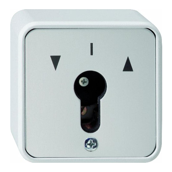
Key switch
10 A 240 V~ for all
DIN half-cylinder
profiles
Switch, 2-pole
0144 30
Push button, 1-pole
0163 30
Gira
Gira
Giersiepen GmbH & Co KG
Electrical installation systems
P.O. Box 1220
42461 Radevormwald
Phone +49 2195 602 - 0
Fax
+49 2195 602 - 191
info@gira.de
www.gira.de
General safety instructions
Electrical devices may only be installed and
mounted by qualified electricians.
Serious injury (e.g. caused by an electric
shock), fire, or material damage is possible
if mounted improperly.
Read these instructions thoroughly and
observe them.
These instructions are part of the product
and must remain with the end customer.
Product features
Thanks to its innovative single-screw
installation system (ESM system), the key
switch insert 10 A/240 V offers important
advantages:
• Fast installation and removal of the entire
switch
• Screwless installation of the locking panel
(plug-in installation)
• Screwless installation of the electrical
contact (plug-in installation)
• Ideal security due to interior lid and flush
half-cylinder profile
• Universal use as surface-mounted or
flush-mounted key switch insert
Scope of supply
• 1x key switch insert
• 1x installation and operating instructions
Ensure the package contents are
complete and undamaged.
When filing complaints, see "Warranty".
Necessary accessories
• Half-cylinder profile, sorted locking type
(Order No. 0001 00)
• Half-cylinder profile, same locking type
(Order No. 0002 00)
• Half-cylinder profile, VdS Class B
(Order No. 0003 00)
Accessories
• Cover plate with symbol (Order No. 0097 30)
• Cover plate without symbol
(Order No. 0098 30)
• Blind controller insert with auxiliary input
(Order No. 0389 00)
Preparation
Prior to installation, first disassemble the
key switch insert as described below.
1. Loosen screw (1) and remove front
panel (2).
2. Carefully pull out seal (3) and lid (4).
3. Push locking panel (5) up (= unlocked)
and pull it out.
4. Remove switching insert (6) from the
housing (7).
7
6
5
4
3
5. Connect protective conductor on the
housing (see arrow).
Switching insert – front and rear
6. Wire the switching insert depending on the
use.
Switch, 1-pole 2-pole (Order No. 0144 30)
Push button, (Order No. 0163 30)
Installation
i
Observe the following when installing the
housing:
• "Surface-mounted" (= APZ) or "flush-
mounted" (= EPZ) installation is possible.
• The opening for the water outlet must
always be on the bottom.
• First, break out one of the three cable
2
openings (on the top, bottom, or rear of
1
the housing).
• Use a screw joint (M20) with lock nut to
fasten the housing.
1. Switch the mains voltage off.
2. Install housing.
3. Return the switching insert in the housing
and tuck the cable in carefully.
4. Insert locking panel and push it down
(= locked).
5. Install half-cylinder profile: insert from
behind through the opening in the lid and
fasten it using the enclosed locking pin
(from left to right for flush-mounted
installation; from right to left for surface-
mounted installation). Insert key into the
half-cylinder profile and turn it (45° position
to the right) so that the cylinder flange is
congruent with the locking panel.
6. Insert lid into the housing.
7. Insert seal.
2I
PI
1I
8. Put on front panel and refasten it with the
screw.
9. Switch on mains voltage.
1
P
2
Technical data
Operating voltage:
Utilisation category:
Conventional
thermal current:
Operating current:
Isolation voltage:
Contacts:
Connections:
Type:
Housing
Material:
Dimensions (WxHxD):
N
M
2
1
2I
1I
P
PI
L
N
M
2
1
P
L
Installation
AC 240 V
AC15
16 A
5 A
300 V
2
max. 2.5 mm
Screw terminal
Diecast aluminium
75 x 75 x 66 mm
2
Advertisement

Related Manuals for Gira 0144 30


Summary of Contents for Gira 0144 30
- Page 1 Operating instructions Necessary accessories Switch, 1-pole 2-pole (Order No. 0144 30) • Half-cylinder profile, sorted locking type (Order No. 0001 00) • Half-cylinder profile, same locking type (Order No. 0002 00) Key switch • Half-cylinder profile, VdS Class B 10 A 240 V~ for all (Order No.
- Page 2 Please submit or send faulty devices postage paid together with an error description to your responsible salesperson (specialist trade/ installation company/specialist electrical trade). The salesperson will forward the devices to the Gira Service Center.
Need help?
Do you have a question about the 0144 30 and is the answer not in the manual?
Questions and answers