Advertisement
Quick Links
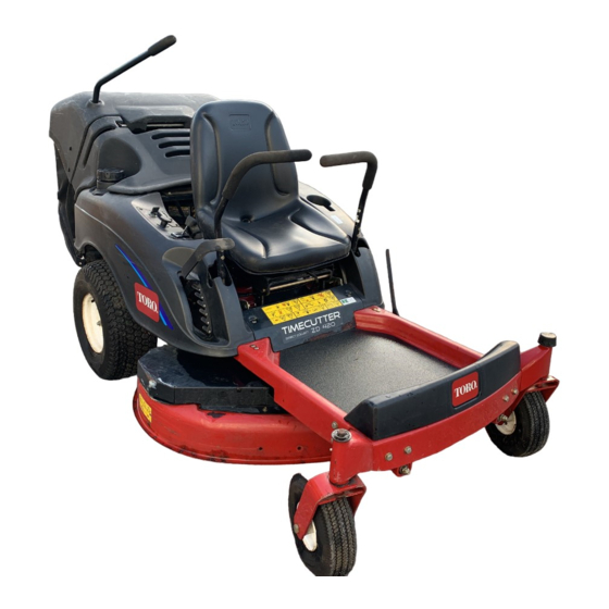
TimeCutter® ZD Riding Mower
Model No. All Models
Loose Parts
Use the chart below to verify that all parts have been shipped.
Step
1
No parts required
Retainer clip
2
Screw, self-tapping (10 x 1/2 inch)
Collection bag
DFS lever
3
Washer
Cotter pin
Ignition Key
4
Operator's Manual
Engine Operator's Manual
Note: Determine the left and right sides of the machine from the normal operating position.
Step
1
Charging the Battery
No Parts Required
Procedure
Bulk electrolyte with 1.260 specific gravity must be
purchased from a local battery supply outlet.
© 2007—The Toro® Company
8111 Lyndale Avenue South
Bloomington, MN 55420
Description
Battery electrolyte contains sulfuric acid
which is a deadly poison and causes severe
burns.
• Do not drink electrolyte and avoid
• Fill the battery where clean water is
• Follow all instructions and comply with
1. Raise the seat to access the battery.
2. Remove the battery from the machine and
3. Clean the top of the battery with a paper towel.
Register at www.Toro.com.
Form No. 3357-921 Rev A
Setup Instructions
Qty.
–
Charge the battery.
2
Install the bag clips.
4
1
1
Install the collection bag.
1
1
1
1
Complete the Setup.
1
contact with skin, eyes or clothing. Wear
safety glasses to shield your eyes and
robber gloves to protect your hands.
always available for flushing the skin.
all safety messages on the electrolyte
container.
place it on a level surface; refer to the Operator's
Manual, Removing the Battery.
Important: Never fill the battery with
electrolyte while the battery is installed in
the tractor. Electrolyte could be spilled on
other parts and cause corrosion.
Original Instructions (EN)
Use
Printed in the USA.
All Rights Reserved
Advertisement

Related Manuals for Toro TimeCutter ZD Series


Summary of Contents for Toro TimeCutter ZD Series
- Page 1 3. Clean the top of the battery with a paper towel. Register at www.Toro.com. Original Instructions (EN) © 2007—The Toro® Company Printed in the USA. 8111 Lyndale Avenue South All Rights Reserved Bloomington, MN 55420...
- Page 2 4. Remove the vent caps from the battery 8. Charge the battery for 10 to 15 minutes at (Figure 1). Slowly pour electrolyte into each 25 to 30 amps or 30 minutes at 4 to 6 amps battery cell until the electrolyte level is up to (Figure 2).
- Page 3 G005849 G005848 Figure 3 1. Bag clip 4. Holes, existing 2. Screw 5. Heat shield 3. Heat shield, backside 6. Bag clip, installed 3. Repeat this procedure for the remaining clip Figure 4 on the opposing side of the heat shield. 1.
- Page 4 Step Completing the Setup Parts needed for this step: Ignition Key Operator’s Manual Engine Operator’s Manual Procedure Checking the Tire Pressure Check the front and rear tires for proper inflation. Refer to Checking the Tire Pressure in the Operator’s Manual for the recommended inflation pressure. Checking the Mower Adjustment The mower deck was leveled at the factory.