Table of Contents
Advertisement
Advertisement
Table of Contents

Related Manuals for Delta Electronics IFD9507


Summary of Contents for Delta Electronics IFD9507
- Page 1 IFD9507 Ethernet Communication Module Application Manual...
- Page 3 Switch off the power before wiring. IFD9507 is an OPEN TYPE device and therefore should be installed in an enclosure free of airborne dust, humidity, electric shock and vibration. The enclosure should prevent non-maintenance staff from operating the device (e.g.
- Page 4 Ethernet Communication Module IFD9507 In buffer registers (IN) in IFD9507 .................... 14 Out buffer registers (OUT) in IFD9507 ..................15 MONITORING FUNCTIONS ......................15 Monitor Bit Registers (MB) ....................... 15 Monitor Word Registerss (MW) ....................16 SETTING UP DEVICE ADDRESS AND RELAY ADDRESS IN SLAVE MODE (FOR MODBUS TCP PROTOCOL ONLY) ...........................
- Page 5 Ethernet Communication Module IFD9507 APPLICATION EXAMPLES – DCISOFT ...................49 12.1 Setting up & Unlocking Password .....................49 12.2 Password Loss (Returning to Default Settings by RS-232)............51 12.3 IP Filter Protection........................51 12.4 Application of E-Mail .........................53 12.5 Monitoring Mode ........................54 12.6 Application of Virtual COM Port....................56 APPLICATION EXAMPLES –...
-
Page 6: Specifications
IFD9507 supports Modbus TCP communication protocol and can conduct remote monitoring by using graphic software or human machine interface. IFD9507 can be the master of Modbus TCP, sending out Modbus TCP instructions and controlling the peripheral equipment. IFD9507 supports Ethernet/IP communication protocol and can control device between Ethernet/IP protocols with Modbus protocol. - Page 7 Ethernet Communication Module IFD9507 Serial communication interface (COM2) Item Specification Interface RJ-11 Number of ports 1 Port Transmission method RS-485 Transmission speed 110, 150, 300, 600, 1200, 2400, 4800, 9600, 19200, 38400, 57600, 115200 Communication Modbus, User Define protocol Terminal block...
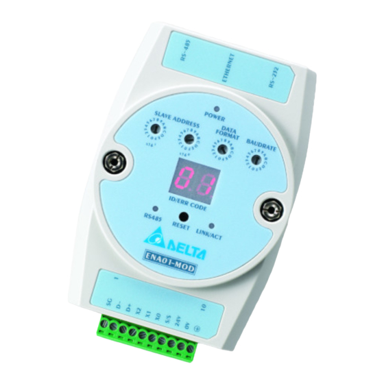
- Page 8 Ethernet Communication Module IFD9507 Product Profile & Outline Dimension Unit: mm Product Profiles 1 Communication ports: RS-485, Ethernet, RS-232 6 RS-485 indicator, Reset button, Ethernet indicator 2 Power indicator 7 Module name 8 RS-485 connector, digital input points, power input 3 Address setup rotary switch。...
-
Page 9: Rj-45 Pin Definition
Ethernet Communication Module IFD9507 RJ-11 PIN Definition RJ-11 sketch PIN. Signal Definition Positive pole for data Negative pole for data Reference RJ-45 PIN Definition RJ-45 sketch Signal Definition Positive pole for data transmission Negative pole for data transmission Positive pole for data receiving... - Page 10 Ethernet Communication Module IFD9507 Data Format Switch setting Format Switch setting Format 7-N-1 7-N-2 8-N-1 8-N-2 7-O-1 7-O-2 8-O-1 8-O-2 7-E-1 7-E-2 8-E-1 8-E-2 Baud Rate for Modbus Communication Switch setting Baud rate Switch setting Baud rate 4,000 9,600 19,200...
-
Page 11: Installation And Wiring
Ethernet Communication Module IFD9507 Installation & Wiring This section gives instructions on how to connect IFD9507 with other devices and how to connect IFD9507 to the network. How to Install How to Connect IFD9507 to Network Connect IFD9507 to the Ethernet hub by twisted pair cable CAT-5e. IFD9507 has auto MDI/MDIX function;... - Page 12 You can read the model code in the program to see if the extension module exists BR# 1: F irmw are Ve rs ion Explanations: The firmware version of IFD9507 is displayed in hex, e.g. H’0100 indicates version V1.00. DVP-PLC Application Manual...
- Page 13 Ethernet Communication Module IFD9507 BR# 2: Re le ase D ate o f th e Vers ion Explanations: Displaying the date in decimal form. 10,000s digit and 1,000s digit are for “month"; 100s digit and 10s digit are for “day". For 1s digit: 0 = morning; 1 = afternoon.
- Page 14 Power supply in low voltage Check if the power supply of the module works normally. 1. Re-power IFD9507. If the error still exists, try step 2. Internal memory detection error 2. Reset IFD9507. If the error still exists, send the module back to the factory for repair.
- Page 15 1 to 4. User can select one of items to connect with others Ethernet/IP device. BR#33: R et urning to Default Sett ing Explanations: IFD9507 will return to default setting when "1” is written into BR#33. BR#33 will be cleared to “0” automatically after the returning. Alarm Registers (AL) in IFD9507...
- Page 16 Explanations: You can designate one RX extension point as the alarm point by setting up the AL register in IFD9507. When the alarm point is triggered, IFD9507 will execute its corresponding function. When b15 of AL0 is set as “1”, the Gateway will execute the event immediately.
-
Page 17: Monitoring Functions
Ethernet Communication Module IFD9507 Out buffer registers (OUT) in IFD9507 OUT# Attribute Content Explanation Default Latched 0~255 Data output buffer Symbol “R” refers to read only; “R/W” refers to read and write. Explanations: The output data was sent to RS-485. - Page 18 Ethernet Communication Module IFD9507 Device Device Device Device Device Device Device Device Device Device Device Device Device Device Device Device MB#2 14: Mo n it ore d Stat us Explanations: Every MB records the status in the 16-bit device. 1 = normal; 0 = abnormal.
- Page 19 Ethernet Communication Module IFD9507 Explanations: Every MW records the values in 1 register. MW#201 MW#202 MW#203 MW#204 MW#205 MW#206 MW#207 MW#208 MW#209 MW#210 Device 1 Device 2 Device 3 Device 4 Device 5 Device 6 Device 7 Device 8 Device 9 Device 10...
-
Page 20: Modbus Communication
Ethernet Communication Module IFD9507 Parameter Explanation Multiple Max. timeout times Trigger Cyclic, changing status, application object O T packet interval Packet interval between originator and target T O packet interval Packet interval between originator and target Modbus Communication Function Codes Supported... -
Page 21: Ethernet/Ip Communication
Ethernet Communication Module IFD9507 Ethernet/IP Communication Service code supported Service Object Service Description Code Get_Attribute_All Returns a predefined listing of this objects attributes Message Router Object Assembly Object Connection Manager Object 0x01 TCP Interface TCP Link 0x05 Reset Invokes the Reset service for the device. - Page 22 Ethernet Communication Module IFD9507 Function Object Name Class ID Code Instance Code Object Type Attribute Description TCP Link 0xF6 0x01 TCP/IP Link Object Object CIP General Status Code (Reference Volume 1:CIP Common Specification Appendix B) General Status Code Status Name...
- Page 23 This section gives instructions on how to set up IFD9507 by DCISoft and explanations on each setup page. IFD9507 is set up by UDP port 20006; therefore, you have to be aware of the relevant settings of the firewall. See the explanations below on the software.
- Page 24 Ethernet Communication Module IFD9507 3. Double-click on the module to be set up to enter the setup page. The first page overviews the basic status of the module. 4. The next page is for basic network setup. Consult your ISP for relevant network settings. For other settings, see BR4~BR6 and BR11~BR13.
-
Page 25: Basic Settings
Ethernet Communication Module IFD9507 10.2 Basic Settings The basic settings include parameters such as module name, network settings and serial communication. The basics 1. Module name: There can be many IFD9507s on the network. Thus, you can set up a module name for each module to... -
Page 26: Network Settings
For example, if the LAN has to be connected to WAN, it will need a gateway to bridge the communication. The IP of the gateway has to be in the same subnet as IFD9507. The default gateway of IFD9507 is 192.168.1.254. - Page 27 Ethernet Communication Module IFD9507 Enter Control Panel → Network Connection → click on “Local Area Connection”. You will see the “Local Area Connection Status” window. Click on “Properties”. Click on “Internet Protocol (TCP/IP)". Enter “192.168.0.1” into IP address. Click on “OK” to complete the IP address setting of the PC.
- Page 28 E-Mail. When the E-Mail is triggered, IFD9507 will send the messages to the user by E-Mail.
-
Page 29: Monitoring Settings
You can enter the text message in the column, and the message will be placed in the subject of the E-Mail and sent to the recipient. IFD9507 is able to contain 1 ~ 3 E-Mail subjects (max. 63 English characters are allowed). - Page 30 Cache mode normally enabled, and Max. data in 16 slaves can be monitored. When the cache mode is enabled, the data you would like to read will be sent back directly from the register in IFD9507. Serial slave mode (used when in Modbus TCP protocol): The instruction sent from the master is received and transferred to the network.
-
Page 31: Ethernet/Ip Settings
Ethernet Communication Module IFD9507 1. Enable IP filter function: Check the box to enable IP filter. 2. IP address: IP addresses that are allowed to establish connections. Maximum 8 IPs are allowed. 3. Netmask: Subnet mask of the IP that is allowed to establish a connection. To see whether the subnet mask is allowed, conduct bitwise AND operation between the allowed IP and subnet mask and destination IP and subnet mask. - Page 32 Ethernet Communication Module IFD9507 Dest IP This is Destination IP address. Timeout (ms) Timetick * Timeout tick = Timeout ※ Available time tick: 20 ~ 215 DVP-PLC Application Manual...
- Page 33 11. Config Instance Configuration instance. Range: 1 ~ 65,535. 10.8 User Defined Settings When you set up user-defined communication protocol for IFD9507, please set up the following parameters. Setting up communication parameter between RS-232/RS-485 serial master and serial slave DVP-PLC Application Manual...
- Page 34 Ethernet Communication Module IFD9507 Listen Port/Destination IP: Range: 1,024 ~ 65,535 Fix Length: Length of the packet to be transmitted. Unit: byte Start Item: DVP-PLC Application Manual...
-
Page 35: Virtual Com
Ethernet Communication Module IFD9507 1 ~ 3 bytes of characters as the start of a packet. Stop Item: 1 ~ 3 bytes of characters as the stop of a packet. 10.9 Virtual COM Virtual COM converts the data transmitted to RS-232 to Ethernet. - Page 36 Ethernet Communication Module IFD9507 Open Virtual COM setup page. DVP-PLC Application Manual...
- Page 37 Ethernet Communication Module IFD9507 Press “OK”, and you will see all the devices connected on the network. Select the module you need and press “OK”. Relevant information of the device will be imported automatically. Press “OK” to complete the setup.
-
Page 38: Security Settings
Ethernet Communication Module IFD9507 10.10 Security Settings To prevent the set values in IFD9507 from being modified, you can set up passwords to lock the settings in IFD9507. Setting up password 1. Password setup: Check the "Modify” box to set up the password. -
Page 39: Returning To Default Settings
Once the password is locked, all the pages cannot be set up unless you unlock the password. However, if you set up IFD9507 by RS-232, you can return the setting to default one whether the password is locked or not. For example, if you have locked IFD9507 but forget the password, you have to return IFD9507 to default setting by RS-232, and all the settings will return to default ones. - Page 40 This section gives instructions on how to set up IFD9507 by homepage and explanations on each configuration page. IFD9507 is set up by UDP port 20006; therefore, you have to be aware of the relevant settings of the firewall. See the explanations below on the homepage.
- Page 41 Ethernet Communication Module IFD9507 11.2 Basic settings The basic settings include parameters as module name, network settings and series communication. Please consult your Internet service provider for relevant network settings. For other settings, please refer to BR4 ~ BR6 and BR11 ~ BR13.
- Page 42 E-Mail. When the E-Mail is triggered, IFD9507 will send the messages to the user by E-Mail.
- Page 43 Ethernet Communication Module IFD9507 1. Mail alarm setup: There are 3 mail alarms to be setup. Check the boxes to enable the alarms. The alarms can be triggered by “falling" or “rising". 2. See 10.4 for how to set up SMTP server/Mail From/E-mail Subject of Event/Recipient E-Mail Address columns.
- Page 44 Ethernet Communication Module IFD9507 See 10.6 for how to set up. 11.5 Security Settings To prevent the set values in IFD9507 being modified, you can set up passwords to lock the settings in IFD9507. Setting up IFD9507 password 1. Password setup: Maximum 4 characters are allowed.
-
Page 45: Returning To Default Setting
Check “Factory Setting” box and click on “Yes”. Note: If you set up IFD9507 by RS-232, you can return to settings to default ones whether the password is locked or not. It will take approximately 10 seconds to return to default settings, so DO NOT switch off the power within the 10 seconds. - Page 46 Cache mode normally enabled, and Max. data in 16 slaves can be monitored. When the cache mode is enabled, the data you would like to read will be sent back directly from the register in IFD9507. Setting up Slave Mode monitoring functions...
- Page 47 Relay IP address: serial master IP 11.8 Ethernet/IP You can read data in designated addresses in different equipment in the network by setting up IFD9507.The data can be temporarily stored in IFD9507 for fast storing and acquisition. Setting up Slave Mode connection parameters...
- Page 48 Ethernet Communication Module IFD9507 1. Dest IP This is Destination IP address. 2. Timeout (ms) Timetick * Timeout tick = Timeout ※ Available time tick: ※ Max. Timeout tick: 255. 3. Trigger There are three trigger types. The cyclic used to describe event that repeat in regular. Production occurs when a change of state is detected by application object.
-
Page 49: User Define
Ethernet Communication Module IFD9507 11.9 User Define You can define your own format for data to be transmitted. The items to be defined include the fixed length, start item and stop item. Select RS-232 or RS-485 to connect the device. - Page 50 The stop item of data. Range: 1 ~ 3 When the start item and stop item are set, IFD9507 will transmit data following the start item and stop item. If the transmission time exceeds the Modbus time-out, IFD9507 will dispose of incomplete data.
- Page 51 12 Application Examples – DCISoft 12.1 Setting up & Unlocking Password Application Setting up password by IFD9507 configuration (1) Set up password in IFD9507. Steps (2) Unlock IFD9507. 1. See 10.1 for the connection and how to set up the communication.
- Page 52 Ethernet Communication Module IFD9507 4. Open the setup page again, and IFD9507 is now locked by the password. You cannot open any of the settings now. Enter the password and press “Confirm”, and you will be able to unlock the editing function on other pages.
- Page 53 (2) Supposed the password is forgotten, return to default settings through RS-232. 1. Use DVPACAB2A30 cable to connect the PC and IFD9507. Open the setup page. 2. Check “Factory Setting” box and the warning dialog box will appear. Click on “Yes” to return to default settings (in approx.
- Page 54 Ethernet Communication Module IFD9507 4. Enter “172.16.0.1” in No. 2 IP and “255.255.255.0” in No. 2 Netmask column. Click on “OK” to complete the setting. Only the equipment within the UP range can be connected. DVP-PLC Application Manual...
- Page 55 Ethernet Communication Module IFD9507 12.4 Application of E-Mail Application Sending E-Mail to notify the administrator when Alarm 1 is triggered. (1) Check “Alarm 1” to enable it. (2) Set the IP of SMTP server to ” 192.168.1.99” and "Mail From” to “Message@Delta”...
- Page 56 (5) Monitor word data in station address 4, H100. (6) Monitor bit quantity: 3; monitor word quantity: 3 1. See 10.1 for how to set up communication. 2. Open IFD9507 Configuration page and switch to “Monitor” page. DVP-PLC Application Manual...
- Page 57 Note: When the cache mode is enabled, you do not need to modify the station address and device address. You will read data from IFD9507, in which way you will be able to speed up the reading. DVP-PLC Application Manual...
- Page 58 Ethernet Communication Module IFD9507 12.6 Application of Virtual COM Port Through the virtual COM port, IFD9507 is able to transmit the data sent to RS-232 to the Ethernet by connencting to the software supporing serial ports, e.g. Delta’s WPLSoft, Application VFDSoft and ASDA-Soft.
- Page 59 Ethernet Communication Module IFD9507 Open Virtual COM setup page. DVP-PLC Application Manual...
- Page 60 Ethernet Communication Module IFD9507 Press “OK”, and you will see all the devices connected on the network. Select the module you need and press “OK”. Relevant information of the device will be imported automatically. Press “OK” to complete the setup.
- Page 61 Ethernet Communication Module IFD9507 Once the setup is successful, you can see the virtual COM you set in the Device Manger. 2. Using Virtual COM in Delta VFDSoft Open Delta VFDSoft. Setting up communication format (COM Setup) Enter the virtual COM (COM2) set in the previous steps to “Com Port” column. Next, enter the communication format of VFD-E (38400, 7, E, 1) and press “Test"...
- Page 62 Ethernet Communication Module IFD9507 Press “OK”, and IFD9507 will be able to communicate with VFD-E by VFDSoft. DVP-PLC Application Manual...
- Page 63 13 Application Examples – AB Software (Revision:2.10.118.0) 13.1 Serial Slave Using Delta PLC DVP28SV11T to control AB PowerFlex 40P via IFD9507. Configure 22-COMM-E IP Use AB software “Driver Explorer Application” to Set the PowerFlex40P+22CommE IP. 1. Open Driver Explorer Application.
- Page 64 Ethernet Communication Module IFD9507 4. Select “Connect Serial Point-to-Point” in Explore. 5. Select “Parameter List” in 22-COMM-E Ethernet/IP and enter “IP” in IP Addr Cfg1~Cfg4 and “Netmask” in Subnet Cfg1~Cfg4. DCISoft configuration 1. Open DCISoft “Basic” configuration screen. 2. Select “Serial Slave” in Master Configuration.
- Page 65 STOP:111000000011001 H7019 Reverse RUN:111000000101010 H702A 4. Select which communication index you want. Write 1~4 to DVPIFD9507 BR15 (H000F). Use WPL MODWR instruction to select the DVP IFD9507 BR (H0500) index. 5. Set the I/O Enable Flag (BR14). DVP-PLC Application Manual...
- Page 66 Use WPL MODWR instruction to write “0101” set I/O enable Flag. 13.2 Serial Master Using AB PLC 1769-L32E to write Delta PLC DVP28SV11T bit and register via IFD9507. Configure RSLinx 1769-L32E 1. Open RSLinx and configure drivers 2. Select RS232 device and click “Add New”...
- Page 67 Ethernet Communication Module IFD9507 3. Select Com port and click “Auto-Configure”. When it is successful, it will show successful messages. Configure IFD9507 1. Open DCISoft “Basic” configuration screen. 2. Select “Serial Master” in Master Configuration. 3. Select “Static” in IP Configuration.
- Page 68 Ethernet Communication Module IFD9507 Configure RSLogix 5000 1. Select “New”. 2. Select controller type “1769-L32E” and type Name click “OK”. 3. Add new Ethernet module. DVP-PLC Application Manual...
- Page 69 Ethernet Communication Module IFD9507 4. Select “communications” module. 5. Select “ETHERNET-MODULE” and click “OK”. DVP-PLC Application Manual...
- Page 70 Ethernet Communication Module IFD9507 6. Enter module name. Select Comm Format “Data-INT”. Enter instance “101”, Size “100”, Out Instance “100”, Output Size “100”, Configuration Instance “6” and, Configuration Size “0” and IP: ”192.168.1.99”. 7. Enter Requested Packet Interval ”500.0 ms” and click “OK”...
- Page 71 Ethernet Communication Module IFD9507 8. Open MainRoutine screen 9. Create New Tag “SW1” (Use SW1 to control instruction ON/OFF) 10. Using Move instruction move data to “ENA01EIP: O.Data” register. Ex:Set Delta PLC Y0 (H0500) ON Send instruction MODBUS TCP:06 01 05 05 00 FF 00 (1) H0006: Mov “06”...
- Page 72 Ethernet Communication Module IFD9507 11. Download this program and make the PLC 1769-L32E go online. 12. Toggle Bit ”SW1”. DVP-PLC Application Manual...
Need help?
Do you have a question about the IFD9507 and is the answer not in the manual?
Questions and answers