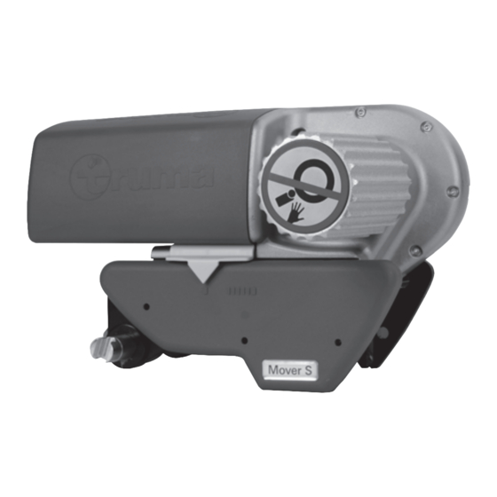
Truma Mover S Installation & Operation Instructions
Hide thumbs
Also See for Mover S:
- User manual (11 pages) ,
- Installation & operation instructions (69 pages)
Summary of Contents for Truma Mover S
- Page 1 Mover S Version UK Operation instructions Page 2 Installation instructions Page 7 To be kept in the vehicle! Comfort on the move...
-
Page 2: Installation Example
Mover S Version UK (M2) Installation example 1 Remote handset 2 Toggle crank 3 Drive motor 4 Drive roller 5 Electronic control unit 6 Battery 7 Cross actuation device... -
Page 3: Safety-Related Instructions
General instructions Mover S The Mover S has been designed to cope with inclines of up to approx. 25 % bearing a gross weight of 1200 kg or 15 % Safety-related instructions bearing a gross weight of 1800 kg on a suitable surface. -
Page 4: Remote Hand Set Led Flash Codes And Acoustic Signal
Changing the batteries in the remote handset Operation instructions Please be sure to use leak proof micro - batteries only, type LR 03, AAA, AM 4, Remote Handset MN 2400 (1.5 V). a = On / Off slide switch When fitting new batteries ensure the polarity is correct! ❙... -
Page 5: Hitching To A Tow Car
“ON“. If the fault cannot be remedied, please contact your dealer or Maintenance the Truma Service department (see Truma Service Booklet or www.truma.com). Please do not allow the drive units to become soiled with coarse road material. When you are cleaning the caravan, spray the Mover with a water hose to dissolve mud etc. -
Page 6: Manufacturer's Terms Of Warranty
– for parts subject to wear and in cases of natural wear and Mover S, Mover SE, Mover TE manoeuvring aid tear, – as a result of using parts that are not original Truma parts in 3. Complies with the requirements of the following the units, EC directives –... - Page 7 185 min. 30 max. 48 Intended use The Mover S has been built for use with single-axis caravans min. 60 • with a gross weight of up to 1800 kg. max. 1860 max. 2400 The Mover S weighs approx.
-
Page 8: Special Accessory Installation
Contact your dealer if necessary. Detailed installation instructions are provided with the relevant mounting set. The Mover S is not approved for installation on caravans / trailers with any other chassis! Place the mounting set (b) on the vehicle frame and secure... - Page 9 Place covering plate onto housing and fix in position with 3 guide pins in each case (knock in with a hammer or Truma can supply a spacer plate set for compensating for screwdriver handle). height differences of up to 45 mm (part no. 60010-66000, 2 pcs.
-
Page 10: Installation Of Motor Cables And Control Unit
Installing the cross actuation device Connecting diagram Please ensure that the drive rollers are not resting against the Installation in Drive Drive tyres (at both sides)! front of axle motor motor Battery Slide the connecting tubes (1) into the middle tube (2) with the holes facing the outside. - Page 11 (e.g. on the wardrobe door)! Ask Truma to the Mover is uniform! Excess cable must be routed in wavy send you a sticker, if necessary.
- Page 12 Notizen, Notes, Nota...
- Page 13 Notizen, Notes, Nota...
- Page 15 ✂ Mover S Version UK...
- Page 16 In Germany, always notify the Truma Service Centre if problems are encountered; in other countries the relevant service partners should be contacted (see Truma Service Booklet or www.truma.com). Having the equipment model and the serial number ready (see type plate) will speed up processing.


Need help?
Do you have a question about the Mover S and is the answer not in the manual?
Questions and answers