Table of Contents
Advertisement
Quick Links
L
I
G
INSTALLATION AND SAFETY INSTRCUTIONS
ITEM NO.:6000 2SN
SAFETY PRECAUTION
• WARNING –To make sure power is off before attempting installation.
• WARNING – Support Directly From Building Structure.
• WARNING –To reduce the risk of fire, electric shock, or injury to persons, unplug or disconnect the
appliance from the power supply before the fan installation, cleaning, or servicing.
• WARNING –Suitable for use with solid-state speed controls.
• WARNING –To Reduce The Risk Of Personal Injury, Do Not Bend The Blade Brackets When Installing The
Brackets, Balancing The Blades, Or Cleaning The Fan. Do Not Insert Foreign Objects In Between Rotating Fan
Blades.
• The installation is to be in accordance with the National Electrical Code, ANSI/NFPA 70-1999 and local
codes. Consult a qualified electrician if in double.
• WARNING – To Reduce The Risk Of Electric Shock, This Fan Must Be Installed With A General-Use,
Isolating Wall Control/Switch.
• All set screws must be checked, and retightened where necessary, before installation.
• After making the wire connections, the wires should be spread apart with the grounded conductor and
the equipment-grounding conductor on one side of the outlet box and the ungrounded conductor on the
other side of the outlet box.
• The splices after being made should be turned upward and pushed carefully up into the outlet box.
• Conductor of a fan identified as grounded conductor to be connected to a grounded conductor of power
supply, conductor of fan identified as ungrounded conductor to be connected to an ungrounded conductor of
power supply, conductor of fan identified for equipment grounding to be connected to an
equipment-grounding conductor.
• CAUTION–To Reduce The Risk Of Electric Shock, Disconnect The Electrical Supply Circuit To The Fan
Before Installing Light Kit.
H
T
I
N
G
1
PARTS & ACCESSORIES
Transmitter Kit
Transmitter
6
5
1
4
2
3
1hr
3hr
6hr
Assembly Kit
Expansion Bolt x 4
Canopy
Downrod
Housing
Blade
Battery
Wall Screw x 2
3 V
CR2032/3V
Self Tapping Screw
&Washer x 4
2
Advertisement
Table of Contents

Related Manuals for Maxim 60002SN


Summary of Contents for Maxim 60002SN
- Page 1 PARTS & ACCESSORIES Canopy INSTALLATION AND SAFETY INSTRCUTIONS Downrod ITEM NO.:6000 2SN Housing SAFETY PRECAUTION • WARNING –To make sure power is off before attempting installation. • WARNING – Support Directly From Building Structure. Blade • WARNING –To reduce the risk of fire, electric shock, or injury to persons, unplug or disconnect the appliance from the power supply before the fan installation, cleaning, or servicing.
- Page 2 INSTALLATION INSTRUCTION INSTALLATION INSTRUCTION Screw (1) STEP 1A - CONCRETE CEILING Lock Pin (2) SWITCH OFF THE ELECTRICAL MAINS AT THE CIRCUIT BREAKER FUSE BOX. Hanger Ball (3) Expansion Bolts (2) 1) Use the Mounting Bracket (1) as a guide, Canopy (4) mark the spots where the 4 Expansion Bolts (2) Mounting...
- Page 3 INSTALLATION INSTRUCTION INSTALLATION INSTRUCTION STEP 2 Safety Wire Clamp 1) Remove the Clevis Pin (8), Nut (9), Spring Washers (11), Flat Washers(12) & Bolt (10) on Coupling (14). 2) Loosen the Screw (1) from Hanger Ball (3), remove the Hanger Ball (3) and Lock Pin (2). 3) Route the wires and safety wire from the motor through the Downrod (7).
- Page 4 TRANSMITTER FUNCTION INSTALLATION INSTRUCTION STEP 4 Led Driver TRANSMITTER SETTING SWITCH OFF THE ELECTRICAL MAINS AT This DC motor is equipped with self-learning frequency function transmitter. Read all the steps THE CIRCUIT BREAKER FUSE BOX. BEFORE proceeding. Each step must be followed exactly in order to program the transmitter. 1) Connect wires from receiver to Light To use factory pre-programmed setting –...
- Page 5 TRANSMITTER FUNCTION TRANSMITTER FUNCTION Forward / Reverse Natural wind Power off Fan speed (6 speed) Timer Forward Reverse Fan rotates anti-clockwise creating a Fan rotates clockwise creating an upward downward airflow delivering a cooling airflow moving warm air off the ceiling effect.
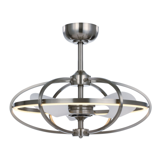
- Page 6 5. Use only soft or lint-free cloth to clean the light fan. Model No. of blades Fan width Light bulb Voltage 60002SN 695mm 1 x 47W LED 110-120V~ 60Hz 6. Please dry the light fan by cold-blast air after cleaning, in order to prevent dangerous Nett...
Need help?
Do you have a question about the 60002SN and is the answer not in the manual?
Questions and answers