
Related Manuals for INOXPA LR Series


Summary of Contents for INOXPA LR Series
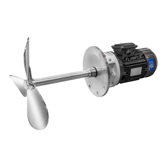
- Page 1 INSTALLATION, SERVICE AND MAINTENANCE INSTRUCTIONS SIDE-ENTRY AGITATOR LR / LM Manual Original 20.025.30.01EN (0) 2019/04...
- Page 2 Electromagnetic Compatibility Directive 2014/30/EU Applicable harmonized standards: UNE-EN ISO 12100:2012 UNE-EN 14120:2016 The technical file has been prepared by the signer of this document in INOXPA. David Reyero Brunet Technical Office Manager Banyoles, 7th February, 2019 The serial number may be preceded by a slash and by one or two alphanumeric characters...
-
Page 3: Table Of Contents
9.4. Dimensions of LR side-entry agitator ......................20 9.5. Dimensions of LM side-entry agitator ......................21 9.6. Exploded drawing and parts list of LR side-entry agitator ................22 9.7. Exploded drawing and parts list of LM side-entry agitator ................23 INOXPA S.A.U. 20.025.30.01EN · (0) 2019/04... -
Page 4: Generalities
risk to the environment due to the type of substances released. 2.3. WARRANTY Any warranty will be void immediately and lawfully and, additionally, INOXPA will be compensated for any civil liability claims submitted by third parties, in the following cases: ... -
Page 5: Safety
Electric hazard Important instruction for the protection of the equipment and its functions ATTENTION 3.2. GENERAL SAFETY INSTRUCTIONS Read the instruction manual carefully before installing and starting the agitator. Contact INOXPA in case of doubt. 3.2.1. During the installation Technical Specifications... - Page 6 The maximum operating conditions of the agitator should not be exceeded. Nor should the operating parameters for which the agitator was initially designed be modified without written authorisations from INOXPA. Do not leave loose parts on the floor. Do not disassemble the agitator until the switchboard has been disconnected. Remove the fuses and disconnect the power cable supplying the motor.
-
Page 7: General Information
Each agitator has performance limits. The agitator was selected for a given set of mixing conditions when the order was placed. INOXPA shall not be held responsible for any damage that might be suffered or malfunctioning of the equipment of the information provided by the buyer is incomplete or incorrect (e. -
Page 8: Installation
When receiving the agitator, check the packaging and its content to ensure that it matches the delivery note. INOXPA packs the agitator in their fully assembled form or disassembled on a case-by-case basis. Ensure that the agitator has not been damaged in any way. If it is not in good conditions and/or any parts are missing, the carrier must submit a report as soon as possible. - Page 9 40 4 kW Motor speed 200 200 rpm Type of agitation elements marine propeller Number of agitation elements one agitation element two agitation elements Name of the agitator LR side-entry agitator with gear motor INOXPA S.A.U. 20.025.30.01EN · (0) 2019/04...
- Page 10 110 11 kW Motor speed 1500 rpm 1000 rpm Type of agitation elements marine propeller Number of agitation elements one agitation element two agitation elements Name of the agitator LM Side-entry agitator with motor INOXPA S.A.U. 20.025.30.01EN · (0) 2019/04...
-
Page 11: Transport And Storage
Department for information on any particular application. If required, the approximate dimensions for the deflector for different tank diameter are shown in the next figures and the next table: VERTICALS: HORIZONTAL: Outside Salient Built-in INOXPA S.A.U. 20.025.30.01EN · (0) 2019/04... -
Page 12: Electrical Installation
Force should never be applied to the end of the agitator shaft, as it can easily suffer permanent damage. ATTENTION Check the alignment of the agitator shaft with the half shaft once its assembly is completed. INOXPA S.A.U. 20.025.30.01EN · (0) 2019/04... -
Page 13: Start-Up
ATTENTION Do not modify the operating parameters for which the agitator was initially designed without written authorisation from INOXPA (risk of damage and user hazard). Follow the instructions for use and the safety requirements described in the instructions manual for the tank in which the agitator is mounted. - Page 14 The tank must be fitted with protective devices and safety equipment. Consult the manufacturer’s instructions manual. ATTENTION Introducing an object or solid raw material may cause the agitation component and other mechanical parts to break and compromise its safety or guarantee. INOXPA S.A.U. 20.025.30.01EN · (0) 2019/04...
-
Page 15: Troubleshooting
The attached table lists solutions to problems that may arise while operating the agitator. It is assumed that the agitator has been properly installed and that is has been selected correctly for the specific application. Contact INOXPA if technical assistance is required. Motor overload... -
Page 16: Maintenance
If the agitator is out of service for a considerable period of time, clean and treat the parts with VG46 mineral oil. The shaft must be stored in the horizontal position and on wooden supports or on supports of a similar material. INOXPA S.A.U. 20.025.30.01EN · (0) 2019/04... -
Page 17: Disassembly And Assembly Of The Agitator
Place the O-ring (80) on the agitator shaft (05). Install the agitator in the flange of the tank. Finally, mount the propeller (02) firmly on the agitator shaft (05), checking that it will not become loose. INOXPA S.A.U. 20.025.30.01EN · (0) 2019/04... - Page 18 Maintenance ØD 51,5 61,5 INOXPA S.A.U. 20.025.30.01EN · (0) 2019/04...
-
Page 19: Technical Specifications
LR 1.10-20007-1-400 LR 1.10-20015-1-500 LR 1.10-20030-1-600 LR 1.10-20040-1-650 Type agitator Weigh (kg) LM 1.10-4015-1-175 LM 1.10-4030-1-200 LM 1.10-4055-1-225 LM 1.10-4075-1-250 LM 1.10-4110-1-275 LM 1.10-6011-1-200 LM 1.10-6022-1-225 LM 1.10-6030-1-250 LM 1.10-6055-1-275 LM 1.10-6075-1-300 LM 1.10-6110-1-350 INOXPA S.A.U. 20.025.30.01EN · (0) 2019/04... -
Page 20: Dimensions Of Lr Side-Entry Agitator
Technical Specifications 9.4. DIMENSIONS OF LR SIDE-ENTRY AGITATOR Dimensions (mm) Type agitator LR 1.10-20005-1-325 LR 1.10-20007-1-400 LR 1.10-20015-1-500 1.165 LR 1.10-20030-1-600 1.205 LR 1.10-20040-1-650 INOXPA S.A.U. 20.025.30.01EN · (0) 2019/04... -
Page 21: Dimensions Of Lm Side-Entry Agitator
Type agitator LM 1.10-4015-1-175 LM 1.10-4030-1-200 1.000 LM 1.10-4055-1-225 1.000 LM 1.10-4075-1-250 1.000 LM 1.10-4092-1-250 1.295 LM 1.10-4110-1-275 LM 1.10-6011-1-200 LM 1.10-6022-1-225 1.000 LM 1.10-6030-1-250 1.000 LM 1.10-6055-1-275 1.295 LM 1.10-6075-1-300 1.295 LM 1.10-6110-1-350 INOXPA S.A.U. 20.025.30.01EN · (0) 2019/04... -
Page 22: Exploded Drawing And Parts List Of Lr Side-Entry Agitator
Mechanical seal Flange AISI 316L Shaft guard Methacrylate Hexagonal screw Hexagonal screw Hexagonal screw Hexagonal screw Flat washer Flat washer Flat washer Flat washer Allen stud Allen stud Bearing support Steel O-ring EPDM Reduction gearbox INOXPA S.A.U. 20.025.30.01EN · (0) 2019/04... -
Page 23: Exploded Drawing And Parts List Of Lm Side-Entry Agitator
Flange AISI 316L Shaft guard Methacrylate Hexagonal screw Hexagonal screw Hexagonal screw Hexagonal screw Flat washer Flat washer Flat washer Flat washer Allen stud Allen stud Bearing support Steel O-ring EPDM IEC Standard motor INOXPA S.A.U. 20.025.30.01EN · (0) 2019/04... - Page 24 How to contact INOXPA S.A.U.: Contact details for all countries are continually updated on our website. Please visit www.inoxpa.com to access the information. INOXPA S.A.U. Telers, 60 – 17820 – Banyoles – Spain Tel.: +34 972 575 200 – Fax.: +34 972 575 502...
Need help?
Do you have a question about the LR Series and is the answer not in the manual?
Questions and answers