
Subscribe to Our Youtube Channel
Related Manuals for Control Technology 2553


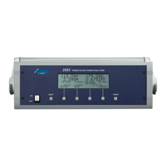
Summary of Contents for Control Technology 2553
- Page 1 CTI 2553 TWO CHANNEL ISOLATED MAG METER INPUT MODULE INSTALLATION AND OPERATION GUIDE Version 2.4 CTI Part #062-00120-024 2553IOG 092205...
- Page 3 Copyright © 2005 Control Technology Inc. All rights reserved. This manual is published by Control Technology Inc., 5734 Middlebrook Pike, Knoxville, TN 37921. This manual contains references to brand and product names which are tradenames, trademarks, and/or registered trademarks of Control Technology Inc. Siemens® and SIMATIC® are registered trademarks of Siemens AG.
- Page 4 CT I 2553 Installation and O peration G uide...
-
Page 5: Preface
PREFACE This Installation and Operation Guide provides installation and operation instructions for the CTI 2553 Two Channel Isolated MAG METER Module for SIMATIC® 505 Series programmable controllers. We assume you are familiar with the operation of SIMATIC® 505 Series programmable controllers. - Page 6 CT I 2553 Installation and O peration G uide...
-
Page 7: Usage Conventions
Notes alert the user to special features or procedures. CAUTION: Cautions alert the user to procedures which could damage equipment. WARNING: Warnings alert the user to procedures which could damage equipment and endanger the user. CT I 2553 Installation and O peration G uide... - Page 8 CT I 2553 Installation and O peration G uide...
-
Page 9: Table Of Contents
REPAIR POLICY ............. 21 CT I 2553 Installation and O peration G uide... - Page 10 CT I 2553 Installation and O peration G uide...
-
Page 11: Table Of Figures
TABLE OF FIGURES Figure 1 The Model 2553 2-Channel Isolated MAG METER Input ......v Figure 2 Word Map ............2 Figure 4 Overrange/Underrange Truth Table . - Page 12 CT I 2553 Installation and O peration G uide...
-
Page 13: Chapter 1. Description
The first incoming pulse enables both the pulse counter and 5 MHz clock counter. The 2553 counts pulses and clocks until the clock counter is half full. On the next pulse input, the 2553 computes the frequency based on the number of 5 MHz clock pulses counted and the number of incoming pulses counted and outputs the value to the PLC. -
Page 14: N-Tooth Count Mode
1.2.2 N-Tooth Count Mode In N-Tooth count mode, the 2553 measures the amount of time of a full revolution of the wheel (based on the number of teeth entered in dip switch). The N-Tooth count mode is useful for compensating for errors introduced by wheel wobble (an effect that occurs when the wheel being measured is not perfectly round). -
Page 15: Overrange/Underrange Reporting
With no frequency input, the 2553 will report 0 in the data register (see Figure 2). The overrange/underrange bit (see Figure 3) will be set to 0. For frequencies under 76 Hz, the 2553 will report 0 in the data register (see Figure 2). The overrange/underrange bit (see Figure 5) will be set to 1. - Page 16 CT I 2553 Installation and O peration G uide...
-
Page 17: Chapter 2. Installation
The following sections discuss these important considerations. 2.2 Calculating the I/O Base Power Budget The 2553 requires 2.5 watts of +5V power from the I/O base. Use this figure to verify that the base power supply capacity is not exceeded. 2.3 Unpacking the Module Open the shipping carton and remove the special anti-static bag which contains the module. -
Page 18: Configuring The Module
I/O backplane. 2.4 Configuring the Module The Model 2553 must be configured to operate in normal counting mode or N-Tooth counting mode. The module must also be configured to report the measurements in "Frequency" or "Period" and digital filtering/no filtering mode before inserting the module into the I/O base. As shipped, the module is configured for normal counting mode, "Frequency"... -
Page 19: Selecting Normal Count Mode Or N-Tooth Count Mode
2.4.5 Selecting Input Signal Conditioning Each of the inputs of the Model 2553 may be configured to support bipolar, positive pulse, negative pulse or open collector applications. Jumpers JP5 for Channel 1 and JP7 for Channel 2 allow each channel to be independently configured. -
Page 20: Open Collector Conditioning
Each input channel may be driven by an external device with open collector output drive. Jumpers JP8 and JP9 are used to configure the input channels for open collector operation. Figure 8 Open Collector Selection CT I 2553 Installation and O peration G uide... -
Page 21: Standard Shipping Configuration
Figure 9 Open Collector External Device 2.4.7 Standard Shipping Configuration The Model 2553 is shipped from the factory with both channels configured for normal operation and with bipolar signal conditioning. WARNING: The module must not be inserted into the I/O rack while power is applied. -
Page 22: Wiring The Input Connectors
Avoid placing low voltage wire parallel to high energy wire (if the two wires must meet, cross them at a right angle). Avoid bending the wire into sharp angles. Use wireways for wire routing. Avoid placing wires on any vibrating surface. Figure 10 Input Connectors CT I 2553 Installation and O peration G uide... - Page 23 CT I 2553 Installation and O peration G uide...
-
Page 24: Connecting The Shield Wiring
2.6.1 Connecting the Shield Wiring Control Technology Inc. recommends that all wires be shielded twisted pair with a foil wrap shield and a separate drain wire and that they be installed in a metallic conduit. Use Belden cable 8761 or equivalent which contains a foil wrap shield and a separate drain wire. -
Page 25: Figure 12 Typical Wiring Diagram
Figure 12 Typical Wiring Diagram Figure 13 Typical Application CT I 2553 Installation and O peration G uide... -
Page 26: Checking Module Operation
In this example, the 2553 module is inserted in slot 1 in I/O base 0. Data for channel 1 appears in word location WX1, data for channel 2 appears in word location WX2. Overrange/Underrange bits appear in word location WX3. -
Page 27: Chapter 3. Troubleshooting
If after consulting the chart above, you are unable to diagnose or solve the problem, contact your local distributor or CTI at 1-800-537-8398 for further assistance. CT I 2553 Installation and O peration G uide... - Page 28 CT I 2553 Installation and O peration G uide...
-
Page 29: Specifications
Accuracy: ±1 Hz Module Power from Base: 2.5 Watts @ +5 VDC Isolation: 1500 VDC channel-to-channel 1500 VDC channel-to-PLC Field Wiring Connector: Removable, accepts 12-26 AWG Mechanical: Size single-wide 505 module CT I 2553 Installation and O peration G uide... - Page 30 Humidity, Relative: 5% to 95% (non-condensing) Shipping Weight: 1.5 lbs. (0.68 Kg) Agency Approvals Pending: UL, UL for Canada FM Class 1 Div 2, CE Specifications subject to change without notice. CT I 2553 Installation and O peration G uide...
-
Page 31: Limited Product Warranty
CTI. Control Technology Inc. reserves the right to make changes to the Product in order to improve reliability, function, or design in the pursuit of providing the best possible Product. CTI assumes no responsibility for indirect or consequential damages resulting from the use or application of this equipment. - Page 32 CT I 2553 Installation and O peration G uide...
-
Page 33: Repair Policy
Failure to observe static control precautions may void the warranty. For additional information on static control precautions, contact CTI's main office at 1-800-537-8398. CT I 2553 Installation and O peration G uide...
Need help?
Do you have a question about the 2553 and is the answer not in the manual?
Questions and answers