
Subscribe to Our Youtube Channel
Related Manuals for Avitech Titan 9000 Series


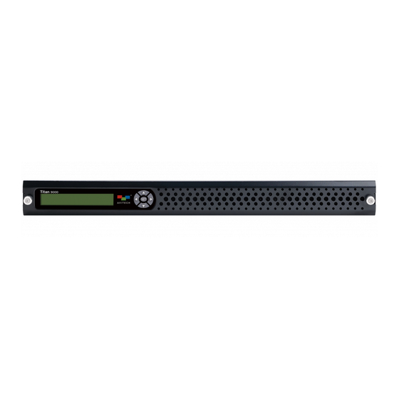
Summary of Contents for Avitech Titan 9000 Series
- Page 1 User Manual Titan 9000 Multiviewing experience taken to the next level Revision 1.0.0, (May, 2014)
-
Page 2: About This Manual
Except as expressly written by Avitech International Corporation, the furnishing of this document does not provide any license to patents, trademarks, copyrights or other intellectual property of Avitech International Corporation or any of its affiliates. -
Page 3: Table Of Contents
Contents About This Manual........................ii Technical Support........................ii Warranty............................ vi Limitation of Liability....................... vi Extended Warranty Options....................vi Services and Repairs Outside the Warranty Period............. vi Regulatory Information ......................vi Federal Communications Commission (FCC) Statement............ vi European Union CE Marking and Compliance Notices ............vi Australia and New Zealand C-Tick Marking and Compliance Notice ......... - Page 4 4.5.4 Visual Studio......................49 4.5.5 Available Windows....................51 4.5.6 Copy Window Properties..................53 4.5.7 Undo/Redo Changes...................55 4.5.8 Align Windows.....................55 4.5.9 Copy Window Size ....................56 4.5.10 Remove Horizontal/Vertical Spacing ..............57 4.6 Log Window ........................57 5. Basic Setup Using the Phoenix-Q Software ............. 59 5.1 File Menu ..........................59 5.2 Edit Menu..........................61 5.3 View Menu ........................62 5.4 System Menu........................65...
- Page 5 For Windows 7 .......................152 Appendix F Resetting to the Factory-Default State ..........153 Appendix G Compatibility With Tally Interface Device ..........154 G.1 Using the Pacific GPIO Box as GPI Interface .............154 G.2 Sony Production Switcher ....................156 Appendix H ScreenCropT Utility ................. 158 H.1 ScreenCropT Utility Control Panel ................158 H.2 Using the ScreenCropT Utility Together With the Synergy Freeware .....160 H.3 Cropping Feature ......................163...
-
Page 6: Warranty
Avitech’s liability under this warranty shall not exceed the purchase to meet FCC emission limits. Avitech is not responsible for any radio or price paid for the defective product. In no event shall Avitech be liable... -
Page 7: Getting Started
1. Getting Started The Titan 9000 Series is a modular card based multiviewer. Each card can receive up to 4 input signals and up to 4 cards can be installed in the 1RU chassis. Users can monitor 4 HDMI/DVI/VGA/YPbPr sources via HD 1080p output. - Page 8 Ear with screw RS-485 Cascading Cable (optional – (already installed on Titan 9000 upon order when purchasing 2 or more Titan 9000) for assembly on to rack mount) Proprietary RJ-45 to RS-232 (DB9-FM) Cable ® DVI to HDMI Adapter (optional) (optional) –...
- Page 9 The following items are included if optional rack mount kit is ordered, refer to the “Rack Mount Assembly Reference Guide” for details. Rack Tray Ear (left and right pc) Ear-A (2 pcs) Ear-B (2 pcs) Used on 700/750/800mm rack depth Tray (27.56/29.53/31.49 inch) Screw 3*4mm (4 pcs)
-
Page 10: Product Features
Supports DVI, features 4 DVI outputs (via a HDMI to DVI adapter) Supports cascading, features an HDMI input for cascading Supports Avitech’s Phoenix-Q configuration interface via Ethernet connection Supports TSL through serial interface (RS-232) or Ethernet (UDP) Supports General Purpose Input/Output through Ethernet... -
Page 11: Specifications
2. Labels BMP label UMD – (under monitor display) 3. Alarms Video loss Audio high Audio low Audio lost Out of Phase 4. Tally 5. Audio meter 6. Digital clock / user logo 7. External Linear Time Code (LTC) 8. Safe area, aspect ratio detection 9. - Page 12 1360×768, 60Hz 1366×768, 60Hz 1400×1050, 60Hz (reduced blanking)/60Hz/75Hz 1440×900, 60Hz 1440×1050, 60Hz 1600×1200, 60Hz 1680×1050, 60Hz 1920×1080i, 50Hz/60Hz 1920×1080p, 50Hz/60Hz 1920×1200, 60Hz (reduced blanking) Automatic sensing, the following input signals are supported: 640×350, 85Hz 640×400, 85Hz 640×480, 60Hz/72Hz/75Hz/85Hz 720×400, 85Hz 480p, 59Hz 480i, 59Hz 576p, 50Hz...
- Page 13 Automatic sensing, via adapter in DVI-I IN port; input signals supported: 640×480, 60Hz/72Hz 640×512, 60Hz 800×600, 50Hz/56Hz/60Hz/72Hz/75Hz 848×480, 60Hz 852×480, 60Hz 960×540, 60Hz 960×620, 60Hz 960×680, 60Hz 1024×576, 60Hz/72Hz 1024×768, 50Hz/60Hz/70Hz/75Hz/85Hz 1152×864, 75Hz 1152×900, 66Hz/76Hz 1200×900, 72Hz 1280×720, 50Hz/59.94Hz/60Hz/75Hz 1280×768, 50Hz/56Hz/60Hz/75Hz 1280×960, 60Hz/70Hz/75Hz 1280×1024, 50Hz/60Hz/72Hz/75Hz/76Hz/85Hz (through adapter)
- Page 14 Titan 9000 – (4H) Input Automatic sensing, the following input signals are supported: 640×350, 85Hz 640×400, 85Hz 640×480, 60Hz/72Hz/75Hz/85Hz 720×400, 85Hz 480p, 59Hz 480i, 59Hz 576p, 50Hz 576i, 50Hz 800×600, 56Hz/60Hz/72Hz/75Hz/85Hz 848×480, 60Hz 1024×768, 60Hz/70Hz/75Hz/85Hz 1152×864, 75Hz HDMI 1280×720, 50Hz/60Hz (HDMI type A) 1280×768, 60Hz (reduced blanking)/60Hz/75Hz/85Hz 1280×800, 60Hz...
- Page 15 1680×1050, 60Hz 1920×1080i, 50Hz/60Hz 1920×1080p, 50Hz/60Hz 1920×1200, 60Hz (reduced blanking) Transmission of audio signal is included when passing through the DVI port using the DVI to HDMI adapter. Output Normal/VESA output timing; 8-bit/10-bit HDMI color depth; user configurable: 1920×1200 (WUXGA) 50Hz/60Hz 1920×1080 (HD 1080) 50Hz/60Hz 1680×1050 (WSXGA+) 50Hz/60Hz/75Hz 1600×1200 (UXGA) 50Hz/60Hz/75Hz...
- Page 16 1. One Titan 9000 – (HOB card) can do 1×2 wall display. Likewise, two Titan 9000 – (HOB cards) can do 2×2 wall display. 2. The system only allows a set of “Bezel Gap Adjustment” configuration at a time (via Phoenix-Q software). Make sure to use an identical model and size of monitors when outputting a signal source simultaneously to two 1×2 wall display or two 2×2 wall display.
-
Page 17: Connections To The Titan 9000
Rainier 3G Plus – (1 card) Output Normal/VESA output timing; 8-bit/10-bit HDMI color depth; user configurable: 1920×1200 (WUXGA) 50Hz/60Hz 1920×1080 (HD 1080) 50Hz/60Hz 1680×1050 (WSXGA+) 50Hz/60Hz/75Hz 1600×1200 (UXGA) 50Hz/60Hz/75Hz 1600×900 (HD+) 60Hz 1440×900 (WSXGA, WXGA) 50Hz/60Hz/75Hz HDMI and DVI 1400×1050 (SXGA+) 50Hz/60Hz/75Hz (through HDMI to 1360×768 (WXGA) 50Hz/60Hz/75Hz DVI adapter) - Page 18 Figure 1-3 Titan 9000 – (2H2V Card) Components Rear Panel DVI connector for HDMI/DVI/VGA/YPbPr input sources (a DVI to HDMI adapter or DVI to VGA adapter or DVI to YPbPr adapter may be required) DVI-I IN Note: Transmission of audio signal is included when passing through the DVI port using the DVI to HDMI adapter but is not included when using the DVI to VGA, DVI to YPbPr adapters HDMI IN...
- Page 19 Note: This port is not available for connecting to a computer for configuration and control (Phoenix-Q utility). Likewise, it cannot be used for entering the Avitech ASCII Protocol (AAP) X command interface. For setup through Avitech Phoenix-Q utility (network connection)
- Page 20 Figure 1-5 Titan 9000 Chassis Component Rear Panel (chassis) Remove the cover plate to install any of the following: Titan 9000 – (2H2V card) Card Cover Plate Titan 9000 – (4H card) Titan 9000 – (HOB card) Control Card Remove the cover plate to install the Titan 9000 – (control card) Cover Plate Connects to the 24 V DC power adapter Power...
-
Page 21: Hardware Configuration
2. Hardware Configuration This chapter discusses the process of installing a card into Titan 9000 chassis. To prevent any damage to hardware components as well as avoid any injury, make sure to turn off power coming from the power strip to the Titan 9000 before making any changes to the hardware configuration. 2.1 Installing New Card on Blank Slot The Titan 9000 chassis accept any of the following cards: Titan 9000... - Page 22 Step 3. Use a flat screwdriver to unscrew the left and right puller screws on the control board. Figure 2-3 Remove the Left and Right Puller Screws on Control Board Step 4. Use the just removed puller screws and screw it to both sides of new card. Then, align both sides of the card to the rails, and slide all the way into the chassis.
-
Page 23: Removing A Previously Installed Card
2.2 Removing a Previously Installed Card Step 1. Use a flat screwdriver to unscrew the left and right puller screws on the control board module. Figure 2-7 Remove the Left and Right Puller Screws on Control Board Step 2. Use the just removed puller screws and screw it to both sides of the card to be removed. Step 3. -
Page 24: Cascading
3. Cascading Cascading is the technique of “daisy-chaining” multiple Titan 9000s through an HDMI display and a digital control backbone. This connection allows the combined Titan 9000s to operate as a single integrated system. Up to 10 different Titan 9000s can be combined in this fashion to create extremely large and complex systems with the ability to simultaneously monitor audio, video, and computer signals on the same display. - Page 25 Step 3. Click to remove the checkboxes on the left. Then drag the desired configuration (either left or right illustration below) and then click OK. Figure 3-3 Phoenix-Q Software: Set Subgroup Configuration There is no need to make any adjustments in the HDMI OUT item in Properties panel as the software smartly does it.
-
Page 26: Example 2: Cascade 2 Cards And Independent Quads
The following figure illustrates the above setup. Figure 3-5 Cascade 2 Cards and Duplicate Display Illustration 3.1.2 Example 2: Cascade 2 cards and independent quads Step 1. Make sure that 2 card ID belong to the same group, while the other 2 card ID are each assigned a group by itself. - Page 27 There is no need to make any adjustments in the HDMI OUT item in Properties panel as the software smartly does it. Figure 3-7 Phoenix-Q Software: Properties – HDMI OUT (Display Source) The following figure illustrates the above setup. Figure 3-8 Cascade 2 Cards and 2 Independent Quad Illustration...
-
Page 28: Example 3: Cascade 3 Cards And Independent Quad
3.1.3 Example 3: Cascade 3 cards and independent quad Step 1. Make sure that card ID 1 and 2 and 4 belong to the same group, while card ID 3 is assigned a group by itself. Verify this as shown on the Group View tree found on the left panel of the Phoenix-Q software. -
Page 29: Example 4: Cascade All 4 Cards
The following figure illustrates the above setup. Figure 3-11 Cascade 3 Cards and 1 Independent Quad Illustration 3.1.4 Example 4: Cascade all 4 cards Step 1. Make sure that all 4 card ID belong to the same group. Verify this as shown on the Group View tree found on the left panel of the Phoenix-Q software. - Page 30 There is no need of any adjustments in the HDMI OUT item in Properties panel as the software smartly does it. Figure 3-13 Phoenix-Q Software: Properties – HDMI OUT (Display Source) The following figure illustrates the above setup. Figure 3-14 Cascade 4 Cards Illustration...
-
Page 31: External Cascading
3.2 External Cascading Step 1. Set the rotary ID on the first Titan 9000 to 0, set the rotary ID on the second Titan 9000 to 1, set the rotary ID on the third Titan 9000 to 2, and so forth (can be other values except F as long as they are different from each other’s setting). - Page 32 The following illustration shows a typical setup of cascaded Titan 9000. Figure 3-15 Cascaded Titan 9000 Illustration...
-
Page 33: Example 1: Take Hdmi Output Of Any Card To The Next Chassis' Cascade Input
3.2.1 Example 1: Take HDMI output of any card to the next chassis’ cascade input To be able to display all 32 input source windows (16 from each chassis) in one monitor, make sure to assign all 8 cards (4 from each chassis) to the same group. Likewise, assigning card(s) to another group allows display of second group’s window on a second monitor. - Page 34 Upon selecting “Card 2” for “HDMI 1” then only the 8 windows of (card ID 1 and 2) + 16 windows of chassis ID 2 will be displayed. Figure 3-18 HDMI Output of Card ID 1 to the Next Chassis’ Cascade Input Illustration 2 Upon selecting “Card 3”...
- Page 35 Upon selecting “Card 4” for “HDMI 1” then all 16 windows of (card ID 1 and 2 and 3 and 4) + 16 windows of chassis ID 2 will be displayed. Figure 3-20 HDMI Output of Card ID 1 to the Next Chassis’ Cascade Input Illustration 4 Card ID 2 output to the next chassis’...
- Page 36 Card ID 3 output to the next chassis’ cascade input. Upon selecting “Card 1” for “HDMI 3” then only the 4 windows of (card ID 1) + 16 windows of chassis ID 2 will be displayed. Upon selecting “Card 2” for “HDMI 3” then only the 8 windows of (card ID 1 and 2) + 16 windows of chassis ID 2 will be displayed.
- Page 37 Card ID 4 output to the next chassis’ cascade input. Upon selecting “Card 1” for “HDMI 4” then only the 4 windows of (card ID 1) + 16 windows of chassis ID 2 will be displayed. Upon selecting “Card 2” for “HDMI 4” then only the 8 windows of (card ID 1 and 2) + 16 windows of chassis ID 2 will be displayed.
-
Page 38: Example 2: Assign Any Or Multiple Cards (Internal Cascade) To The Cascade Output
3.2.2 Example 2: Assign any or multiple cards (internal cascade) to the cascade output To be able to display all 48 input source windows (16 from each of the 3 chassis) in one monitor, make sure to assign all 12 cards (4 from each of the 3 chassis) to the same group. Likewise, assigning card(s) to another group allows display of second group’s window on a second monitor. - Page 39 To assign the input source signals of card ID 1 and 2 only from chassis ID 2 to be displayed– select “Card 2” for “HDMI 4” Only the 8 windows of (chassis ID 2 : card ID 1 and 2) + 16 windows of chassis ID 1 + 16 windows of chassis ID 3 will be displayed.
- Page 40 To assign input source signals of card ID 1 and 2 and 3 only from chassis ID 2 to be displayed– select “Card 3” for “HDMI 4” Only the 12 windows of (chassis ID 2 : card ID 1 and 2 and 3) + 16 windows of chassis ID 1 + 16 windows of chassis ID 3 will be displayed.
- Page 41 To assign the input source signals of all 4 cards from chassis ID 2 to be displayed– select “Card 4” for “HDMI 4” All 16 windows of (chassis ID 2 : card ID 1 and 2 and 3 and 4) + 16 windows of chassis ID 1 + 16 windows of chassis ID 3 will be displayed.
- Page 42 To bypass all input source signals of all 4 cards from chassis ID 2– select “Cascade In” for “HDMI 4” Only the 16 windows of chassis ID 1 + 16 windows of chassis ID 3 will be displayed. Figure 3-28 Assign Any or Multi-cards to the Cascade Output Illustration 5...
-
Page 43: Phoenix-Q Configuration
4. Phoenix-Q Configuration The Avitech Phoenix-Q program requires no installation. Just copy the system files to your computer’s hard drive. This chapter introduces the Phoenix-Q software for setting up the Titan 9000. 1. Make sure the Titan 9000 is powered on and connected properly to your computer through Ethernet before launching the Phoenix-Q software. -
Page 44: Starting Up The Phoenix-Q Software
Step 3. The following window will appear to signify a successful communication. Click OK to exit. Figure 4-2 IP Address Pinged Successfully 4.3 Starting Up the Phoenix-Q Software Step 1. Run the Phoenix-Q software by double-clicking Phoenix-Q.exe. Step 2. Make sure you have set the correct IP address (see Appendix E for details). Step 3. - Page 45 The computer will start to search for your Titan 9000. Figure 4-4 Phoenix-Q Software: Connection Progress When cascading the Titan 9000 make sure each chassis has a different rotary ID setting selected (e.g., 1 – 2 – 3) on their rear chassis. The Group View window will list the card(s) found and will initially be listed under Idle Group.
- Page 46 Step 4. Click System Configuration. Figure 4-6 Phoenix-Q Software: Click “System” ”Configuration” The Group Setup window will appear. Figure 4-7 Phoenix-Q Software: Group Setup...
- Page 47 Step 5. To assign the grouping drag the Idle Device on the left panel to the desired Group # on the right panel (e.g., Group 001). Figure 4-8 Phoenix-Q Software: Assign Group # to Idle Device Or, click the One Device Per Group button to assign a card to each group or click All Devices in Group 1 to assign all cards to belong to Group 1.
- Page 48 After dragging/assigning the card, it is displayed as belonging to the assigned group. Figure 4-9 Phoenix-Q Software: Idle Device Assigned to Group 001 Step 6. Repeat the previous step for any additional Idle Device(s), if any. Next, click OK to exit the Group Setup window.
-
Page 49: Obtaining The Umd (Under Monitor Display) Data From Router
The next figure shows sample idle devices assigned to groups. The “[1.1]” appearing before the card name signifies the chassis ID and card ID number. Hence “[1.2]” would signify chassis ID 1 and card ID 2. The “(O:H)” appearing after the card name signifies audio “O”utput that is “H”DMI OUT. Figure 4-11 Phoenix-Q Software: Chassis and Card ID Place the mouse pointer over a specific card ID to show various information such as “Master IP”... - Page 50 Then click OK to confirm system disconnection via Phoenix-Q software. Figure 4-14 Phoenix-Q Software: Confirm Disconnection The progress of disconnection will appear on screen. Figure 4-15 Phoenix-Q Software: Disconnection Progress Step 2. Click System Options. Figure 4-16 Phoenix-Q Software: Click “System” ”Options”...
- Page 51 Step 3. On the Options screen click External Device and make sure that Device Enable is set On. Figure 4-17 Phoenix-Q Software: Enable External Device Step 4. Make sure that the IP Address corresponds to the IP address of the computer running the …...
- Page 52 Step 5. Lastly, make sure that the Port Number shown is correct. If not, enter the value directly or click the up/down arrow button. Then click OK to exit the Option screen setup. Figure 4-19 Phoenix-Q Software: Enter Correct Port Number Make sure the value appearing for both IP Address and Port Number are similar to the value entered in the tpcGW utility, they must be to be able to successfully connect to the router.
-
Page 53: Window Layout
4.5 Window Layout 4.5.1 Arranging Windows (by Group) For a quick layout setup of your video windows, right-click the Group ### tab to access the Group Layout menu. Select from 2×2 up to 13×13 as possible grid positions on the monitor. The layout size available for your particular model will depend on the monitor’s resolution as well as the smallest window size limitation. -
Page 54: Resizing Window
4.5.2 Resizing Window Perform the following steps to resize a window: Method 1. Right-click a window, and then select Size. Followed by the desired preset size. Figure 4-22 Phoenix-Q Software: Select a Preset Size Method 2. Resize a window by dragging the border of a window to the desired size. Keep in mind that there is a scaling limitation for each window that limits the minimum scalable size to 128×80 pixels for NTSC/PAL video (320×180 for Titan 9000-HOB). -
Page 55: Visual Studio
4.5.4 Visual Studio For a quick global view of monitors installed in the studio, use the Visual Studio tab to easily glance the present set ups. Step 1. To configure how the monitors will appear in the Visual Studio tab, right-click anywhere inside the Visual Studio tab and click “Visual Studio Setting.”... - Page 56 Step 3. On the Visual Studio tab select the desired layout by right-clicking anywhere and clicking “Layout.” Select from 2×2 up to 10×10 as possible grid positions, as well as specify a fixed 1 row by “N” columns or “N” rows by 1 column Figure 4-26 Visual Studio: Select the “Layout”...
-
Page 57: Available Windows
Color Setup To set the border color and label color (font and background), right-click anywhere on a window and click Color Setting. Figure 4-29 Visual Studio: Set the Border and Label Color Auto Arrange Allow the system to automatically arrange the layout of the windows appearing in the Visual Studio tab. - Page 58 To turn image window back on (re-enable), you can use any of the below 2 methods: Method 1. Select the desired image window to be turned on and in the “Properties” tab click “Image Enable” “On”. Figure 4-32 Properties Tab: Turn On Image Window Method 2.
-
Page 59: Copy Window Properties
Placing the mouse pointer on top of a window residing in the “Available Windows” tab displays information about the image window. Figure 4-34 Available Windows Tab: Image Window Information 4.5.6 Copy Window Properties Right-click an item (with icon) on the Properties window (except with icon) and click the following to quickly apply the settings to –... - Page 60 The properties that can be copied include the following: Window size: 1. width, and 2. height Label: 1. on/off switch 2. type (ANSI or BMP label) 3. font color, and 4. background color Aspect ratio: 1. on/off switch 2. sync type, and 3.
-
Page 61: Undo/Redo Changes
4.5.7 Undo/Redo Changes Clicking the allow you to undo the previous step; while clicking the allow you to redo the previous step that was undone. To undo or redo multiple actions click the drop-down arrow symbol beside the undo/redo button, then highlight and click the actions to be undone or redone. Click the scrollbar to highlight more than 6 actions. -
Page 62: Copy Window Size
4.5.9 Copy Window Size This function allows a set of windows to copy the width, height, and size of a window appearing on screen. For example, clicking the Make Same Width button ( ) would cause the selected windows to have the same width. To modify the window size: Step 1. -
Page 63: Remove Horizontal/Vertical Spacing
4.5.10 Remove Horizontal/Vertical Spacing You can eliminate the space between a set of windows horizontally or vertically. You can choose how you want the windows to line up in relation to each other. For example, clicking the Remove Vertical Spacing button ( ) eliminates the vertical space between a set of windows. - Page 64 Step 2. Assign a filename and click Save to store the data. Figure 4-40 Phoenix-Q Software: Save Log Window Information You can also refer to your computer’s hard drive (C:/Avitech/Backup/Backup_date_time/Log/ folder) for various system log messages text file. Figure 4-41 Phoenix-Q Software: Location of Auto-save Log File...
-
Page 65: Basic Setup Using The Phoenix-Q Software
5. Basic Setup Using the Phoenix-Q Software This chapter introduces you to the Phoenix-Q software for setting the features of your Titan 9000; as well as familiarizes you with the menus appearing on the Phoenix-Q software. Some items appearing on the menus of the Phoenix-Q software may not be available (grayed-out). 5.1 File Menu Figure 5-1 Phoenix-Q Software: File Menu All the presets you create are stored in the Titan 9000 flash memory, not on your computer. - Page 66 1. The file extension GP# will be automatically added to the filename of a group’s preset. 2. Click to select Save Global Preset (with checkmark) if you wish to save a group preset that can be applied to all the groups. The file extension GLB will be automatically added to the filename. You can delete a file appearing on the Save window by right-clicking the filename and clicking Delete.
-
Page 67: Edit Menu
Step 5. Select a saved file and then click OK to load the preset. Opening a preset file with “GP#” as filename extension loads a single group preset; while opening a preset file with “GLB” as filename extension loads a preset that applies to all groups (global preset). -
Page 68: View Menu
Font Type: Click Font Type to select the Font, Font style, and Size. Then, click OK. Figure 5-7 Phoenix-Q Software: Set Font Properties For Windows 7: When using the Phoenix-Q in a different language other than English the Font “Arial” might not appear as the default font-type. - Page 69 Toolbars and Docking Windows: Enable (with checkmark) or disable display of Standard toolbar, Available Windows panel, Log Window panel, Group View panel, Properties panel, Briefing panel, as well as Customize display. Figure 5-9 Phoenix-Q Software: “Toolbars and Docking Windows” Menu Customize: Click Customize to design the look of the menus and commands appearing on the Phoenix-Q software.
- Page 70 Application Look: Click Application Look to select the overall design and theme of the Phoenix-Q software. Click on the themes title to view the theme. Note: The “dot” in front of Visual Studio.NET 2005 signifies that it is the currently selected theme. Figure 5-11 Phoenix-Q Software: “Application Look”...
-
Page 71: System Menu
5.4 System Menu Figure 5-12 Phoenix-Q Software: System Menu System Menu Connect the computer and Titan 9000 via Ethernet connection; or Connect or Disconnect it. Before connecting make sure that the correct Disconnect configurations are entered under the item Communication. When you have unplugged the Ethernet cable and re-connected it, click Reconnect Reconnect to continue the configuration process. - Page 72 Restore: To manually Restore a preset perform the following steps. Step 1. Set the Titan 9000 to the factory-default value (see Appendix F for details). Step 2. Make sure that the rotary ID setting of the chassis being restored matches the old chassis’ setting (if the restoration to be attempted is not for the same chassis).
- Page 73 When the setup of the Present Configuration window is different from the setup in the Preview Configuration window (e.g., upon selecting Backup_2013_03_05_14_15_10 folder in the Date window) then restore is not allowed by the system and the Restore button remains grayed-out. Step 6.
- Page 74 Setup Speaker ID: When you have 2 or more cascaded chassis ID, Setup Speaker ID allows you to assign each card ID to output to which chassis ID headset connector. Make sure to first assign 2 or more chassis ID cards to the same group. Figure 5-17 Phoenix-Q Software: Click “System”...
- Page 75 Import and Export Labels / Alarm Sound Figure 5-19 Phoenix-Q Software: Click “System” ”Import/Export Label (.txt)” 1. “Label” settings here will affect all the labels of the Groups in the System. 2. These items are only available when the computer is connected to the Titan 9000. 3.
- Page 76 Step 1. Click System Export (.txt) Label and assign a filename. Then click Save. Figure 5-20 Phoenix-Q Software: Export Label Step 2. Open the exported text file. The first row of text provides a guide to the two types of labels (A for ANSI / B for BMP Label).
- Page 77 Figure 5-23 Phoenix-Q Software: Click “System” ”Options” General Backup Path The default backup path “C:\Avitech\Backup\” contains the system configuration, preset files, system log data, and firmware version information. To change the backup path, type the desired path in the Value column (available when Phoenix-Q is not connected to chassis).
- Page 78 … Or click the select folder button “ ” and when the Select Folder screen appears select from the existing folders or click the Make New Folder button to create a new folder. Then click OK to exit. Figure 5-25 Phoenix-Q Software: Select Folder Window General During Program Startup Click the drop-down button (click the cell’s rightmost portion) to select Open Communication window that allows the Phoenix-Q program to automatically open the Communication window...
- Page 79 General New Device Detected Click the drop-down button (click the cell’s rightmost portion) to select Open Group Setup window that allows the Phoenix-Q program to automatically open the Group Setup window when a new device has been detected. Figure 5-27 Options: “System” ”General” ”New Device Detected” To prevent error when detecting the new device it is highly recommended the new device to return to its default setting before connecting it to the present setup.
- Page 80 General Display Device ID (Group View) To display the device ID information in the Group View panel, make sure Display Device ID (Group View) is enabled (set On). Click the drop-down button [click the Display Device ID (Group View) cell’s rightmost portion] to select On. Figure 5-29 Options: “System”...
- Page 81 General HDMI Audio Output Follow SDI / SPDIF Audio Output To allow the HDMI audio output to have the same audio output as SDI (Properties portion – Card Parameters Headphone (Local) Source), make sure HDMI Audio Output Follow SDI / SPDIF Audio Output is enabled (set On).
- Page 82 General Audio Output From Full Screen Window To allow audio output to switch to the window that just entered full screen mode, make sure Audio Output From Full Screen Window is enabled (set On). Click the drop-down button [click the Audio Output From Full Screen Window cell’s rightmost portion] to select On.
- Page 83 General Visual Studio Name Type the Visual Studio group’s new name (up to 30 characters). Figure 5-35 Options: “System” ”General” ”Visual Studio Name” General Display Name Type To change the group’s displayed name, select Custom. Click the drop-down button [click the Type cell’s rightmost portion] to select Custom.
- Page 84 General Display Name Custom Name Type the group’s new name (up to 30 characters). Figure 5-37 Options: “System” ”General” ”Custom Name” Play Special Layout (No Video) Make sure that Play Special Layout when No Video occurs is Enabled (set On). Click the drop- down button (click the Display Type cell’s rightmost portion) to select Quad or Full screen.
- Page 85 Display Type: Quad/Full screen The following sample scenarios may occur: Sample scenario 1 – a single window loses video signal Regardless of the present monitor’s window layout, the quad/full screen layout would be displayed and the single window without video signal would occupy the top-left position/full screen to warn user that the particular window has no video signal.
- Page 86 External Device Device Enable To allow the Phoenix-Q software to get the UMD (under monitor display) data from the router (when necessary) click External Device and make sure that Device Enable is set On. Figure 5-40 Options: “External Device” ”Communication” ”Device Enable” External Device IP Address Make sure that the IP Address corresponds to the IP address of the computer running the tpcGW …...
-
Page 87: Help Menu
External Device Port Number Make sure that the Port Number shown is correct. If not, enter the value directly or click the up/ down arrow button. Then click OK to exit the Options screen setup. Figure 5-42 Options: “External Device” ”Communication” ”Port Number” Make sure the value appearing for both IP Address and Port Number must be similar to the value entered in the tpcGW utility to be able to successfully connect to the router. - Page 88 Firmware Version Step 1. Click Firmware Version. Figure 5-44 Phoenix-Q Software: Firmware Version Step 2. Click Export. Step 3. Assign a filename and click Save to store the data. Figure 5-45 Phoenix-Q Software: Save Firmware Version Information Upgrade Firmware: Click Upgrade Firmware to bring the device’s firmware up-to-date (see “Firmware Upgrade Reference Guide for Titan 9000”...
-
Page 89: Briefing
5.6 Briefing This function allows you to cycle between presets for a slideshow effect. Step 1. Right-click the title bar and when the menu appears, click Add. Figure 5-47 Briefing: Click “Add” Step 2. Enter the Process name, specify the Time (H : M : S), then select the previously saved preset File. -
Page 90: Setting The Group/Card Properties
6. Setting the Group/Card Properties To set the properties of the Titan 9000, click to select the Card on the Group View window (left panel) and the Properties window (right panel) would list the parameters available for setup. Figure 6-1 Phoenix-Q Software: Properties Window Some of the items appearing on the Properties window may or may not be available for your Titan 9000. -
Page 91: Titan 9000-2H2V / 4H Properties Setup
Enable/Disable TSL V3.1 for the configuration of the RS-232 port with a TSL connection. Note: RS-232 port is not for connecting to a computer for configuration (Phoenix-Q utility). Likewise, it cannot be used for entering any Avitech ASCII commands. When configuring, connect the (Master Titan 9000) to the controlling computer via an Ethernet connection and then connect the (Master Titan 9000) RS-232 port to the TSL router. - Page 92 TSL UDP Parameter Enable/Disable TSL V3.1 for configuration of IP port with TSL connection. Make sure to enter the correct UDP Port (User Datagram Protocol) value that matches the connected router. Note: To implement TSL, aside from selecting “Enable” “TSL UMD Properties” must be “On” and “Display Address / Option” must be configured.
- Page 93 HDMI OUT (Display Source) A Titan 9000-HOB card must be assigned a group by itself. Headphone Parameters Mute Turn off the audio output coming from the headphone connected to audio output port. (On / Off) Sound Select whether audio output is one-sided or coming from both sides of the Stereo headphone.
- Page 94 (On / Off) Select the display address. The address should match the TSL controller’s configured address connected to the router output feeding the corresponding Avitech input. Display Address Upon right-clicking Display Address and clicking Quick Setting, set the (0 up to 126) starting and ending number (0-126) to be displayed for each four sources (e.g., Set 100 as the Start Number for Image 1 and set 126 as the End...
- Page 95 Tally Tally1/2/3 Color (LED1/2/3) Select tally color of your preference. Click Others for more color choices (Standard tab) or customize the color (Custom tab) by setting the Hue/ Saturation/Luminance as well as the Red/Green/Blue values. Event Submenu of Tally 1 / 2 / 3. (Serial Event) LED 1/2/3 Turn on or off the LED in case a serial event occurs.
- Page 96 Embedded Audio Select the source of embedded audio signal; from each window’s HDMI Source IN port. (Window 1/2/3/4 embedded audio) Primary Group Assign the primary embedded audio group to belong to group 1/2/3/4. Secondary Group Assign the secondary embedded audio group to belong to group 1/2/3/4. User Logo Enable Allow the display of user logo.
- Page 97 Clock Time Source Activate Time Code feature by selecting RTC, LTC or Counter. You can also synchronize the clock of the Master card by selecting Sync to SNTP Master. The SNTP Time Code feature allows the card to synchronize the clock with an external SNTP time server.
- Page 98 Clock Specify the desired time zone shown on a particular monitor. Time Zone Note: This item is not available when you select Counter in Source. Broadcast Sync Allows card to synchronize the clock with an external SNTP time server. Time Note: This item is only available when you select SNTP in Source.
- Page 99 Clock Label Background Color Specify the clock label’s background color. Click Others for more color choices (Standard tab) or customize the color (Custom tab) by setting the Hue/Saturation/Luminance as well as the Red/Green/Blue values. The following table shows the Properties setting for each window in the Titan 9000-2H2V / 4H. Image Show/hide selected window on monitor.
- Page 100 Image To pan is to move the “zoomed in” area around in the image window. Panning changes the image view in the same way that scrolling moves the image up, down, to the left, or to the right in the image window. When the entire image is not displayed you can quickly pan to see parts of the image that were previously hidden.
- Page 101 Image Allow the detection of closed captioning. “NO C.C” would be displayed if C.C Detect detection is enabled but input signal is without closed captioning. (On / Off) Note: This item only appears for Rainier 3G Plus – (1 card). Standard AFD (active format description) codes provide information about where in coded picture active video is and also "protected area"...
- Page 102 Image Outside Place the label outside the window. (On / Off) Aspect Auto Detect Enable Allow automatic detection of the input signal’s aspect ratio. (On / Off) Upon selecting Default, aspect ratio will follow settings on next two items: Sync Type HD-SDI (fixed at 16:9) and SD-SDI/Composite (4:3/16:9).
- Page 103 Image Audio meter scale: Layout and Alarm Trigger Change . . .
- Page 104 Image Switch: turn on/off any of the following meters METER1_L METER3_L PHASE1 PHASE3 METER1_R METER3_R METER2_L METER4_L PHASE2 PHASE4 METER2_R METER4_R Group: Meter’s 1 & 2 and Meter’s 3 & 4 can be assigned to any of 4 groups. However, (1 & 2) and (3 & 4) cannot share same Group. Phase Meter: 90 deg (default);...
- Page 105 Image Select the audio meter’s group (embedded audio). Meter 1/2 Group Meter 3/4 Group Note: These items only appears for Rainier 3G Plus – (1 card). Select the audio meter’s width. Width (2 / 4 / 6 / 8 / 10 / 12 / 14) Vertical Offset Specify the location of the meter appearing on screen by setting the vertical coordinate.
- Page 106 Image Width Set width of the border for image. (2/4/6) Default Type Set Other Type: Select the type of 3D border for the image. Color Change image border color as each pixel/line can have a different color. (Line 1/2/3/4/5/6) Video Border Enable Display the border of video.
- Page 107 Image Manual Adjustment The Titan 9000-2H2V’s DVI connector allows for VGA/YPbPr input source Manual Image (a DVI to VGA / DVI to YPbPr adapter is required). If the image appears Setting off-centered (does not completely fill the upper and left portion), this function can help correct it.
- Page 108 Image Video Black Activate the “video black” alarm feature. Enable Note: (On / Off) 1. Analog input signal is not supported. 2. This item only appears for Rainier 3G Plus – (1 card) Video Detect Area (L/T/R/B, %) Change . . . Freely adjust the horizontal (Left and Right) and vertical (Top and Bottom) markers to set the scope of area to be monitored when “no video”...
- Page 109 Image Set the time interval to wait before triggering an alarm once the criteria (sensitivity level) for “video freeze” has been detected. Set Duration Note: (5 to 255 seconds) 1. It may take up to one second more than the value of the “Set Duration” parameter to trigger a video freeze alarm.
-
Page 110: Titan 9000-Hob Properties Setup
Image Set “audio alarm” sound playback duration (second) for specific window. Set Playback Note: To shut off alarm sound playback before the time set has elapsed, Duration click “Stop Alarm Sound (System)” icon (will become grayed-out). (5 to 3600 seconds, Always on) Click the cell’s rightmost portion “change”... - Page 111 Note: The RS-232 port is not for connecting to a computer for configuration (Phoenix-Q utility). Likewise, it cannot be used for entering any Avitech ASCII commands. When configuring, connect the (Master Titan 9000) to the controlling computer via an Ethernet connection and then connect the (Master Titan 9000) RS-232 port to the TSL router.
- Page 112 Card Parameters Output Timing Normal output timing is designed for some brands of monitor that do not Normal support the VESA standard. VESA Bezel Gap Turn on or off the display of proprietary test pattern on screen for Adjustment seamless image alignment in 1×2 wall display and 2×2 wall display. (Test Pattern) Note: This item is only available when the item after next is set Wall.
-
Page 113: Setting Group Parameters
Display Sharpness Adjust the sharpness quality of the input signal. (0 to 14) Table 6-2 Phoenix-Q Software: Setting Group/Card Properties for Titan 9000-HOB 6.3 Setting Group Parameters The settings here only affect the cards included in a particular group. Upon right-clicking a particular Group # heading portion the following menu will appear. - Page 114 Click Set Cascade In / Set Subgroup. Depending on the card installed in your Titan 9000, the default cascaded configuration within a particular group will be displayed: – the broken lines signify internal cascading between the cards within a Titan 9000 (left figure below) –...
- Page 115 Click the checkbox to enable (default setting) or disable “cascade in” for each ID number. Disabling (or removing the checkmark) would cause the previous link on the particular ID number to be broken. This would cause the monitor to only display the linked windows after the broken link. Change the ID number designation only (by dragging using the symbol);...
-
Page 116: Appendix A Using The Lcd Panel
Appendix A Using the LCD Panel This chapter discusses the process of using the LCD panel to set up Titan 9000. LCD panel allows for control of the Titan 9000 including; output resolution and signal adjustment, user logo, audio (headphone and HDMI), cascade, HDMI output source, preset file, color correction, clock, window display parameters, alarm, aspect ratio adjustment, safe area and operational status report. - Page 117 Figure A-4 LCD Panel: Menu Tree...
-
Page 118: Navigating The Main Menu
A.2 Navigating the Main Menu 1. Press the button from the default initial screen to enter the main menu. 2. Use the buttons on the front panel to navigate: ( 3. The following sections are setup items on the main menu, details of each are in the following tables, respectively: Resolution Select the desired display resolution and frequency. - Page 119 Audio Not available for Titan 9000 – (HOB card) On: listen to the audio output via headphones. Mute: disable the audio output via headphone feature. On/Off Sound: select the left/right/both channels. Stereo Mono L (left) Mono R (right) Headphone Volume: adjust the volume. –64 up to 12 (level) Source: select from available 4 source windows or pass through.
- Page 120 Preset File User created preset file. Load Preset: recall from the previously saved preset file. Save Preset: save the current parameters as a preset file (preset.GPx). The filename (preset) can be up to 18 characters in length, while the “x” in “GPx” would be assigned automatically based on the current group number (1 up to 99).
- Page 121 Full Screen Not available for Titan 9000 – (HOB card) On: allow the selected window to appear in full screen mode (default setting is OFF). Status Off: window appears in its present configuration. Exit Exit the window full screen menu. Table A-12 Window Full Screen The next 2 items in the LCD panel “Display AFD”...
- Page 122 Meter Not available for Titan 9000 – (HOB card) On: display the audio meter for the particular window. Status Off: disable the display of the window’s audio meter. Exit Exit the meter setup menu. Table A-16 Window Meter Window Border Not available for Titan 9000 –...
-
Page 123: Navigating The System Parameters Menu
Alarm Not available for Titan 9000 – (HOB card) On: turn on the alarm feature for the particular window. Video Alarm: activate alarm to be triggered when “no video” occur Note: analog input signal is not supported. Status On/Off Audio Alarm: activate alarm to be triggered when “no audio” occur On/Off Off: disable the alarm feature of the window. - Page 124 Table A-26 Lock LCD Panel In case you forgot the password for unlocking the LCD panel, just press both buttons simultaneously and enter “Avitech” (default password). Firmware Version Show the various current firmware version for reference. CB AX (controller board) CB FPGA (field-programmable gate array) Cx Merge FPGA (C stands for card;...
-
Page 125: Appendix B Setting Up 1×2 / 2×2 Wall Display
Appendix B Setting Up 1×2 / 2×2 Wall Display 1. One Titan 9000 – (HOB card) can do 1×2 wall display. Likewise, two Titan 9000 – (HOB cards) can do 2×2 wall display. 2. The system only allows a set of “Bezel Gap Adjustment” configuration at a time (via Phoenix-Q software). Make sure to use an identical model and size of monitors when outputting a signal source simultaneously to two 1×2 wall display or two 2×2 wall display. - Page 126 For a 2×2 wall display configuration, with 4 monitors (identical model and size of monitors) placed together on a wall – connect the first monitor to Card ID 3 DVI-D OUT 1 port, second monitor to Card ID 3 DVI-D OUT 2 port, third monitor to Card ID 4 DVI-D OUT 1 port, and fourth monitor to Card ID 4 DVI-D OUT 2 port.
- Page 127 This setting need be performed only once unless the Titan 9000-HOB card is assigned to a different group. For 2×2 wall display sample configuration Right-click the “Bezel Gap Adjustment (Pixel)” and click “Bezel Gap Adjustment.” The “Bezel Gap Adjustment” window allows Phoenix-Q to calculate (based on the data provided) just how much (pixel) offset is needed to align the image seamlessly in your 2×2 wall display.
- Page 128 monitor (top right position of 2×2 wall display) connected to Card ID 3 DVI-D OUT 2 port. “Display 002 – Chassis ID : 1 / Card ID : 4 / Output : 1” corresponds to monitor (bottom left position of 2×2 wall display) connected to Card ID 4 DVI-D OUT 1 port.
- Page 129 Click the “Apply to HOB output” button. Step 9. For setting the bottom right monitor of 2×2 wall display Select the output port for the bottom right monitor from the “HOB Device” drop-down window. On the “Clear” column click radio button for “Right” and “Bottom” because we do not need to specify both margins for monitor (right bottom position) Click the “Apply to HOB output”...
- Page 130 For 1×2 wall display sample configuration Right-click the “Bezel Gap Adjustment (Pixel)” and click “Bezel Gap Adjustment.” The “Bezel Gap Adjustment” window allows Phoenix-Q to calculate (based on the data provided) just how much (pixel) offset is needed to align the image seamlessly in your 1×2 wall display. Step 1.
- Page 131 On the “Clear” column click radio button for “Left” and “Top” and “Bottom.” Click the “Apply to HOB output” button. Step 7. For setting the right monitor of 1×2 wall display Select the output port for the right monitor from the “HOB Device” drop-down window.
-
Page 132: Software Configuration
Step 4. Disable the “Line” test pattern by selecting “Off” to allow input signal source to be displayed. Step 5. For benefit of duplicating 1×2 or 2×2 wall display configuration to 100m (328ft) distance – For a 1×2 wall display configuration – Connect an Ethernet cable from Card ID 4 HDBaseT 1 port to the first Pacific X-HDUR HDBaseT port;... - Page 133 For the sample 1×2 wall display configuration, “Card 3” would be assigned as the input signal source for the Titan 9000 – (HOB card) under Card Parameters. For the sample 2×2 wall display configuration, “Card 2” would be assigned as the input signal source for the Titan 9000 – (HOB card) under Card Parameters.
- Page 134 Step 5. Manually re-size and rearrange the 5 windows to obtain the below example display.
-
Page 135: Appendix C Setting Up Audio
Appendix C Setting Up Audio Step 1. For 2 or more cascaded chassis ID The System Setup Speaker ID function allows you to assign where each card will output to a particular chassis’ headset connector. Make sure that 2 or more cascaded chassis’ cards belong to the same group. Step 2. - Page 136 Step 3. To further allow audio monitoring via the headphone connected to the headset port of the chassis, make sure to make the correct settings for the items under “Headphone (Local)” (Enable=On and Source). Headphone will be disabled upon selecting “Pass through embedded audio.” “Group View”...
- Page 137 Step 4. Select the audio channel to monitor via headphone. for an eight-channel (7.1) and six-channel (5.1) surround audio system, select from any of the first 2 groups listed in the drop-down menu (Primary Group CH1/CH2 or CH3/CH4 for Titan 9000 card) (Group 1 CH1/CH2 or CH3/CH4;...
- Page 138 Important principles to consider when “SDI Out Type” (for Rainier 3G Plus card) and “HDMI Out Type” (for Rainier 3G Plus and Titan 9000 cards) is available for setting (not grayed out): 1. Upon setting one card in group for Rainier 3G Plus (–Q card) and “System Options HDMI audio output follow SDI audio output Off”.
- Page 139 Step 6. Select the source of embedded audio signal to output to HDMI OUT port of the particular card ID. Only applicable when you select “Local” on the previous item “HDMI Out Type.” Step 7. For Rainier 3G Plus card only – Select the combination of “Primary Group”...
- Page 140 Step 8. Turn on audio meter monitoring. Step 9. Click “Change” in “Layout & Alarm Trigger.” Embedded audio as VU (volume unit) meters can be displayed inside the video window. Embedded audio is divided into four groups (CH1 to CH4), with a master (Meter 1/2) and secondary channel (Meter 3/4) for each group.
- Page 141 The following figure shows the audio meter scale as reference: Outside Allow the location of the audio meter to be outside the video area. (On / Off) Meter 1/2 Group Select the audio meter’s group (embedded audio) to be shown in the Left (6) bars window.
- Page 142 Whereas the VU meter has fairly equal attack and release times, the PPM is characterized by having a very slow fall-back time, taking over 1.5 seconds to fall back 20dB (the specifications vary slightly for Type I and II meters). The reasoning for the slow fall-back was to reduce eye-fatigue and make the peak indication easier to assimilate.
-
Page 143: Sample Illustration 1
Sample illustration 1 Figure C-1 Audio Output From Each Card’s HDMI OUT Port Plus Headset To allow audio output from chassis’ headset port and from each card’s HDMI OUT port – Headphone Parameters Mute Off (chassis level so this includes all 4 cards) Headphone (Local) Enable On (card level so this must be set for each of the 4 cards;... -
Page 144: Sample Illustration 2
Sample illustration 2 Figure C-2 Audio Output From Card ID 3 Image 2 Plus Headset To allow audio output from chassis’ headset port and from card ID 3 image 2 embedded audio – Headphone Parameters Mute Off (chassis level so this includes all 4 cards) Headphone (Local) Enable On (card level so this must be set for card ID 3;... -
Page 145: Sample Illustration 3
Sample illustration 3 Figure C-3 Audio Output From Chassis ID 2 Card ID 4 Image 3 Plus Chassis ID 1 Headset... - Page 146 To allow audio output from chassis ID 1 headset port and from chassis ID 2 card ID 4 image 3 embedded audio– Assign all 8 cards to 1 group System Setup Speaker ID (set chassis ID 2 card ID 4 output audio to chassis ID 1 headset port) Headphone Parameters Mute Off (chassis ID 1;...
-
Page 147: Appendix D Setting Up The Alarm Sound
Appendix D Setting Up the Alarm Sound An audible alarm sound (“WAV” file format only) can be played during occurrence of (no video / video black / video freeze) / (no audio) in each image source window to allow for easy monitoring. This appendix lists the steps to setup playback of alarm sound. - Page 148 Step 4. Click “Change” in “Video Detect Area” to freely adjust the horizontal (Left and Right) and vertical (Top and Bottom) markers to set scope of area to monitor when “no video” occurs. If the Safe Area item has been previously set, Video Alarm will temporarily use the mask area border to help you set Video Alarm.
- Page 149 Step 8. Set the motion sensitivity of image when “video freeze” alarm will be triggered. Adjust the sensitivity according to the signal being monitored, on a range of 1 (for filtering out noise in a noisy signal) to 128 (for a clean signal). Also, the lower the “sensitivity” level set, a “not so noticeable difference”...
-
Page 150: Alarm Sound Setup For No Audio Occurrence
At present, only the “WAV” audio file format is supported. Step 13. To enable alarm sound playback, click “Start Alarm Sound (System)” icon (this functions as the main switch – will become grayed-out). To shut off alarm sound playback before the time set has elapsed (duration), click “Stop Alarm Sound (System)”... - Page 151 Step 5. Select “On” in “Alarm Sound” ”Audio” ”Enable” to activate playback of alarm sound when no audio is detected in a particular image source window. Step 6. Set the “audio alarm” sound playback duration (second) for particular image source window. Step 7.
- Page 152 Step 9. Click “Change” in “Layout & Alarm Trigger.” Click to select (with checkmark) the L(eft) and R(ight) Meter 1/2 / 3/4 to monitor. Then click OK to exit. Step 10. To enable alarm sound playback, click “Start Alarm Sound (System)” icon (this functions as the main switch –...
-
Page 153: Import And Export Alarm Sound
Import and Export Alarm Sound ® Export the “Alarm Sound” parameters to be edited externally using a text editor (e.g., Microsoft Notepad), and then import it. Figure D-1 Phoenix-Q Software: Click “System” ”Import/Export (.txt)” ”Alarm Sound” Step 1. Click System Export (.txt) Alarm Sound and assign a filename. Then click Save. Figure D-2 Phoenix-Q Software: Export Alarm Sound... - Page 154 Step 2. Edit the text in the file (highlighted as shown below). Make sure to follow correct syntax "Video Sound File – file path\filename.wav" where only a space must be located before and after the dash (–). Figure D-3 Phoenix-Q Software: Change Alarm Sound File Step 3.
-
Page 155: Special Layout
D.4 Special Layout Before starting or stopping display of special screen layout when no video occurs, make sure to enable the feature. To find out, click System Options on the Phoenix-Q software’s drop-down menu. The highlighted item must be set at On. Figure D-4 Options: Enable Special Layout Otherwise, the icon would be disabled (grayed-out). -
Page 156: Appendix E Setting Up Static Ip
Appendix E Setting Up Static IP The following two methods allow Titan 9000 to be in same network mask with the connected computer. Method 1: Change the IP Address of the Titan 9000 Master Chassis Step 1. Run the Phoenix-Q software by double-clicking Phoenix-Q.exe. Figure E-1 Phoenix-Q Software: Initial Screen... - Page 157 Step 2. Change the IP address by first clicking the default IP Address: 192.168.0.5 entry in the IP Connection List window. Then, click Change Connection Properties. Figure E-2 Phoenix-Q Software: Click “Change Connection Properties” The present IP address is shown in the IP address field. The corresponding Subnet Mask and Gateway belonging to the present IP address is also displayed.
-
Page 158: Method 2: Change The Ip Address Of The Controlling Computer
Step 3. Enter the new IP address. Edit the Subnet Mask and Gateway as necessary. Then, click OK. The IP address will be changed for the target device (saved to flash memory of Titan 9000). Step 4. Click OK to exit. Figure E-4 IP Address Change Successful Method 2: Change the IP Address of the Controlling Computer... -
Page 159: Appendix F Resetting To The Factory-Default State
Appendix F Resetting to the Factory-Default State Step 1. Power-off the Titan 9000 by cutting off power from the power strip. Step 2. Push the number 2 dip switch located on the control card downward to the ON position. Figure F-1 Push Number 2 Dip Switch Downward Step 3. -
Page 160: Appendix G Compatibility With Tally Interface Device
Appendix G Compatibility With Tally Interface Device The Titan 9000 (together with Pacific GPIO + RS-232 to 422 converter + mini null modem adapter + re-worked serial cable) system supports production switchers and other tally interface devices; via a serial connection. The combined devices can dynamically update monitor wall elements to reflect text and status updates from the device. - Page 161 Step 5. On the Properties window under TSL UMD Properties, make sure that Enable is set On for the Image # of a particular Card ID the Sony switcher wishes to communicate with. Figure G-3 Phoenix-Q Software: Enable Image #’s TSL UMD Properties Step 6.
-
Page 162: Sony Production Switcher
Step 7. Make sure that the Display Type is set at Destination Name (D-Name). Figure G-5 Phoenix-Q Software: Select the Correct Display Type G.2 Sony Production Switcher Titan 9000 can receive dynamic source names and tally information from a Sony switcher. The procedure below describes how to set up Titan 9000 to interface with a Sony production switcher. - Page 163 Step 4. Connect one end of the mini null modem adapter (DB9 male to DB9 male) to the RS-232 to 422 converter; and the other end to the Pacific GPIO RS-232 (1) port. Figure G-7 Physical Connection (Sony Switcher) Only the RS-232 (1) port in Pacific GPIO can be used to connect to the mini null modem adapter. Step 5.
-
Page 164: Appendix H Screencropt Utility
Appendix H ScreenCropT Utility The Titan 9000 comes with a windows-based user interface called ScreenCropT. Avitech’s ScreenCropT utility is easy to use and hosts several powerful tools that include: Input port selection for single or cascaded setup (chassis ID, card ID, image ID) Note: For a cascaded Titan 9000 setup, it is highly recommended to set all the chassis to the same IP address but with different rotary ID setting. - Page 165 Status Information (1) Displays all detected Avitech’s Titan 9000 multiviewers in the same network mask. Devices on Note: In the case of cascaded setup, it is highly recommended to set all Network the Titan 9000 to the same IP address, but set with different rotary ID setting, and then using the “Chassis ID”...
-
Page 166: Using The Screencropt Utility Together With The Synergy Freeware
H.2 Using the ScreenCropT Utility Together With the Synergy Freeware Before using the ScreenCropT utility to control the Titan 9000, you need to set it in the same network mask with the connected computer. Refer to “Appendix E” for details on setting up the network mask. To use the Synergy freeware, perform the following steps for each of the connected computers: Step 1. - Page 167 Step 8. Click to select the checkbox for “Server (share this computer’s mouse and keyboard)” for the first computer you are configuring. The IP address(es) associated with your computer will be listed. Click the “Configure Server” button and proceed to step 9. Or, click to select the checkbox for “Client (use another computer’s keyboard and mouse)”...
- Page 168 Step 9. (If you previously selected “Server” then this step is a continuation of the previous “step 8”) Based on your desired Synergy layout setup (KVM function); you can: drag new screens to the grid or move existing ones around drag a screen to the trashcan to delete it, or double-click a screen to edit its settings.
-
Page 169: Cropping Feature
H.3 Cropping Feature ScreenCropT utility sets 2 instances of “area of interest.” The associate contents can then be transmitted to the intended audiences. To crop areas of interest, perform the following steps. Figure H-3 Cropping a Defined Area of Interest Step 1. - Page 170 When cropping, Left/Top position, Width, and Height are calculated based on module’s input display size. The value for Width and Height must be greater than 20% of the panel width and the panel height. For example, if the module’s input display timing is 1280×1024 @ 60Hz, then the panel width is 1280 and the panel height is 1024.
-
Page 171: Cropped Instances Switching
H.4 Cropped Instances Switching ScreenCropT utility not only crop areas of interest, but it also allows for the selection of 2 separate instances that can be switched accordingly. Perform the following steps to switch between 2 cropped instances. Step 1. Use the drop-down menu to select Instance One or Two, and then set cropping parameters. Step 2. -
Page 172: Pan Anywhere
H.5 Pan Anywhere The “Pan” feature allows transfer of a previously-set area of interest to another portion of the screen by clicking the Repeated Pan checkbox. Upon clicking the Repeated Pan checkbox, the following dialog box will appear. Figure H-6 Pan Instruction Follow the instructions in the dialog box: Place the mouse pointer on any of the 4 cropping corners, and then use the right-mouse button to pan the area of interest.
Need help?
Do you have a question about the Titan 9000 Series and is the answer not in the manual?
Questions and answers